Acromag 5028-626 User manual

APZU Cable Breakout
(5028-626)
USER’S MANUAL
ACROMAG INCORPORATED
30765 South Wixom Road
Wixom, MI 48393-2417 U.S.A.
Tel: (248) 295-0310
Email: solutions@acromag.com
Copyright 2021, Acromag, Inc., Printed in the USA.
Data and specifications are subject to change without notice.
8501151B

APZU Cable Breakout
USER’S MANUAL
Acromag, Inc. Tel: 248-295-0310 - 1 -
http://www.acromag.com
- 1 -
https://www.acromag.com
Table of Contents
Table of Contents
1.0 GENERAL INFORMATION..........................................................................................2
1.1 Intended Audience ...................................................................................................2
1.2 Preface.....................................................................................................................2
1.2.1 Trademark, Trade Name and Copyright Information ............................................................... 2
1.2.2Environmental Protection Statement...................................................................................... 2
1.3 AcroPack APAZ Cable Breakout Information..............................................................2
1.3.1 Ordering Information .............................................................................................................. 2
2.0 PREPARATION FOR USE ...........................................................................................3
2.1 Unpacking and Inspecting .........................................................................................3
2.2 Field I/O Connectors.................................................................................................3
Table 2.1 Field I/O Connector Pin Assignments..................................................................................... 4
FIGURE 1 ...................................................................................................................................6
5028-626 BREAKOUT PANEL.............................................................................................6
FIGURE 2 MALE TO MALE 1-FOOT CABLE......................................................................6
3.0 SPECIFICATIONS....................................................................................................... 10
3.1 Physical ..................................................................................................................10
CERTIFICATE OF VOLATILITY ........................................................................................ 11
REVISION HISTORY ............................................................................................................ 11

APZU Cable Breakout
USER’S MANUAL
Acromag, Inc. Tel: 248-295-0310 - 2 -
http://www.acromag.com
- 2 -
https://www.acromag.com
1.0 GENERAL INFORMATION
1.1 Intended Audience
This users’ manual was written for technically qualified personnel who will
be working with I/O devices using the AcroPack module. It is not intended
for a general, non-technical audience that is unfamiliar with I/O devices and
their application.
1.2 Preface
The information contained in this manual is subject to change without
notice, and Acromag, Inc. (Acromag) does not guarantee its accuracy.
Acromag makes no warranty of any kind with regard to this material,
including, but not limited to, the implied warranties of merchantability and
fitness for a particular purpose. Further, Acromag assumes no responsibility
for any errors that may appear in this manual and makes no commitment to
update, or keep current, the information contained in this manual. No part
of this manual may be copied or reproduced in any form, without the prior
written consent of Acromag,
1.2.1 Trademark, Trade Name and Copyright Information
© 2021 by Acromag Incorporated.
All rights reserved. Acromag and Xembedded are registered trademarks of
Acromag Incorporated. All other trademarks, registered trademarks, trade
names, and service marks are the property of their respective owners.
1.2.2 Environmental Protection Statement
This product has been manufactured to satisfy environmental protection
requirements where possible. Many components used (structural parts,
circuit boards, connectors, etc.) are capable of being recycled. Final
disposition of this product after its service life must be conducted in
accordance with applicable country, state, or local laws or regulations.
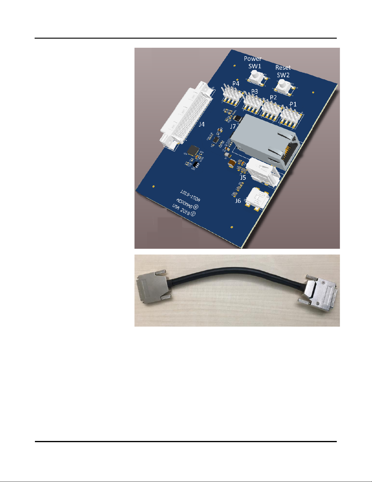
1.3 AcroPack APAZ Cable Breakout Information
The APZU Cable Breakout panel will mate directly to all 68-pin AcroPack
Carriers. The breakout panel and short 68-pin male to male 1-foot cable
(seen below) will bring an ethernet port, USB 2.0 port, UART to USB port,
digital I/O at jumper blocks, and power and reset buttons out to the field.
1.3.1 Ordering Information
The AcroPack ordering options are given in the following table.
Model Number
Description
5028-626
APZU Cable Breakout Panel
Note 1: Operating temperature range for models:-40oCto 85oC.
APZU Cable Breakout
USER’S MANUAL
Acromag, Inc. Tel: 248-295-0310 - 3 -
http://www.acromag.com
- 3 -
https://www.acromag.com
2.0 PREPARATION FOR USE
IMPORTANT PERSONAL AND PRODUCT SAFETY CONSIDERATIONS
It is very important for the user to consider the possible safety implications
of power, wiring, component, sensor, or software failures in designing any
type of control or monitoring system. This is especially important where
personal injury or the loss of economic property or human life is possible. It
is important that the user employ satisfactory overall system design. It is
understood and agreed by the Buyer and Acromag that this is the Buyer's
responsibility.
WARNING: This interfaces to boards with static sensitive components and
should only be interconnected at a static-safe workstation.
2.1 Unpacking and Inspecting
Upon receipt of this product, inspect the shipping carton for evidence of
mishandling during transit. If the shipping carton is badly damaged or water
stained, request that the carrier's agent be present when the carton is
opened. If the carrier's agent is absent when the carton is opened and the
contents of the carton are damaged, keep the carton and packing material
for the agent's inspection.
For repairs to a product damaged in shipment, refer to the Acromag Service
Policy to obtain return instructions. It is suggested that salvageable shipping
cartons and packing material be saved for future use in the event the
product must be shipped.
2.2 Field I/O Connectors
The APZU breakout panel provides a mating interface between the AP
modules via the carrier board 68 pin field I/O connector. The 100 pin ST5-
50-1.50-L-D-P-TR Samtec connector is used on the AcroPack card as board to
board interconnect. This connector will mate with the 100 pin SS5-50-3.00-
L-D-K-TR Samtec connector on the carrier. The stack height is 4.5mm.
Pin assignments are unique to each AP model. Table 2.1 lists signal pin
assignments for the module field I/O connector.

APZU Cable Breakout
USER’S MANUAL
Acromag, Inc. Tel: 248-295-0310 - 4 -
http://www.acromag.com
- 4 -
https://www.acromag.com
Table 2.1 Field I/O Connector Pin Assignments
APZU-304(APZU-301)
14 LVDS (28 TTL)
Field I/O Signal
APZU-303
20 TTL & 3 RS485
Field I/O Signal
APZU Cable Breakout
AcroPack
Module ST5
Pin Number
P1/P2/P3/P4
8-Pin Headers
J5 USB 2.0
TypeA2
Or J6 USB
Mini3
J7
Ethernet4
J4
68 Pin
Champ
Carrier
Connector1
Diff0_P (TTL0)
B26_TTL0
P1-1
1
2
Diff0_N (TTL1)
B26_TTL1
P1-3
35
1
Diff1_P (TTL2)
B26_TTL2
P1-5
2
6
Diff1_N (TTL3)
B26_TTL3
P1-7
36
5
Diff2_P (TTL4)
B26_TTL4
P1-2
3
10
Diff2_N (TTL5)
B26_TTL5
P1-4
37
9
Diff3_P (TTL6)
GND
P1-6
GND P2-7
P4-7
4
14
Diff3_N (TTL7)
B26_TTL7
P1-8
38
13
Diff4_P (TTL8)
B26_TTL6
P2-3
5
18
Diff4_N (TTL9)
B26_TTL9
P2-5
39
17
Diff5_P (TTL10)
B26_TTL8
P2-2
6
22
Diff5_N (TTL11)
B26_TTL11
P2-4
40
21
Diff6_P (TTL12)
B26_TTL10
P2-6
7
26
Diff6_N (TTL13)
B26_TTL13
P2-8
41
25
Diff7_P (TTL14)
B26_TTL12
P3-1
8
30
Diff7_N (TTL15)
B26_TTL15
P3-3
42
29
Diff8_P (TTL16)
B26_TTL14
P3-5
9
34
Diff8_N (TTL17)
B26_TTL17
P3-7
43
33
Diff9_P (TTL18)
B26_TTL16
P3-2
10
38
Diff9_N (TTL19)
B26_TTL19
P3-4
44
37
Diff10_P (TTL20)
B26_TTL18
P3-6
11
42
Diff10_N (TTL21)
GND
P3-8
GND P2-7
P4-7
45
41
Diff11_P (TTL22)
RS485_A_P
P4-3
12
46
Diff11_N (TTL23)
RS485_A_N
P4-5
46
45
Diff12_P (TTL24)
RS485_B_P
P4-2
13
50
Diff12_N (TTL25)
RS485_B_N
P4-4
47
49
Diff13_P (TTL26)
RS485_C_P
P4-6
14
54
Diff13_N (TTL27)
RS485_C_N
P4-8
48
53

APZU Cable Breakout
USER’S MANUAL
Acromag, Inc. Tel: 248-295-0310 - 5 -
http://www.acromag.com
- 5 -
https://www.acromag.com
MIO44_UART1_RX
MIO44_UART1_RX
J6
15
58
MIO45_UART1_TX
MIO45_UART1_TX
J6
49
57
USB_UART1_CTS
USB_UART1_CTS
J6
16
62
USB_UART1_RTS
USB_UART1_RTS
J6
50
61
ULPIO_D_P
ULPIO_D_P
J5
17
66
ULPIO_D_N
ULPIO_D_N
J5
51
65
ULPIO_VBUS
ULPIO_VBUS
J5
18
70
GND
GND
GND P2-7
P4-7
52
69
Eth_LED0
Eth_LED0
J7
19
74
Eth_LED1
Eth_LED1
J7
53
73
PHY_MDI0_P
PHY_MDI0_P
J7
20
78
PHY_MDI0_N
PHY_MDI0_N
J7
54
77
PHY_MDI1_P
PHY_MDI1_P
J7
21
82
PHY_MDI1_N
PHY_MDI1_N
J7
55
81
PHY_MDI2_P
PHY_MDI2_P
J7
22
86
PHY_MDI2_N
PHY_MDI2_N
J7
56
85
PHY_MDI3_P
PHY_MDI3_P
J7
23
90
PHY_MDI3_N
PHY_MDI3_N
J7
57
89
GND
GND
GND P2-7
P4-7
24
94
VCC_3V3
VCC_3V3
P2-1, P4-1
58
93
PS_POR_PB
PS_POR_PB
SW2 Reset
25
98
POWER_EN_PB
POWER_EN_PB
SW1 Power
59
97
Notes (2.1):
1. J4 –Carrier Field I/O 68-pin Champ Manufacturer Name: TE Connectivity Part: 5796055-1
2. J5 –USB Shielded I/O Receptacle Molex 67329-8001
3. J6 –MINI USB I/O Receptacle Tyco Electronics 1-1734035
4. J7 –Ethernet Gigabit MagJack Bel 08261K1T23-F
APZU Cable Breakout
USER’S MANUAL
Acromag, Inc. Tel: 248-295-0310 - 6 -
http://www.acromag.com
- 6 -
https://www.acromag.com
Figure 1
5028-626 Breakout Panel
Figure 2 Male to Male 1-foot
cable
Signal Descriptions:
The I/O signals of the APZU-303 include 20 TTL, three RS485 signal pairs,
UART to USB port, USB 2.0, Ethernet via RJ-45, push button reset, and
power-on push button.
Model APZU-303
20 TTL Signals (P1, P2, P3)
(See Xilinx UG571 UltraScale
Architecture SelectIO
Resources)
Signals B26_TTL0 to B26_TTL19
All I/O signals originate from bank 26 of the Zynq chip. Back 26 is powered
by 3.3 volts. The signals from Bank 26 are High Density (HD) I/O Resources.
HD I/O is designed to support speeds up to 250Mbps interfaces. Bank 26 I/O
signals will support LVTTL and LVCMOS. These signals can be used as input,
output, or bidirectional.

APZU Cable Breakout
USER’S MANUAL
Acromag, Inc. Tel: 248-295-0310 - 7 -
http://www.acromag.com
- 7 -
https://www.acromag.com
The three RS485 signals originate from ADM3062E transceivers. The
transceivers are driven by Zynq PL pins originating from bank 65 of the Zynq
chip. Back 65 is powered by 1.8 volts. The signals from Bank 65 are High-
performance (HP) I/O Resources.
Model APZU-303
Three RS485 Ports (P4)
Field Signals
RS485_A_P, RS485_A_N (Port 1)
RS485_B_P, RS485_B_N (Port 2)
RS485_C_P, RS485_C_N (Port 3)
Low speed 500 kbps data rate for long cables (ADM3062E)
Zynq signals
B65_LVDS0_P (bi-directional data Port 1)
B65_LVDS0_N (direction Control Port 1)
B65_LVDS1_P (bi-directional data Port 2)
B65_LVDS1_N (direction Control Port 2)
B65_LVDS2_P (bi-directional data Port 3)
B65_LVDS2_N (direction Control Port 3)
These Zynq signals originate from Bank 65 and are configured as 1.8-volt
LVCMOS18 signals.
Model APZU-301
28 TTL Signals (P1 to P4)
(See Xilinx UG571 UltraScale
Architecture SelectIO
Resources)
All I/O signals originate from bank 65 of the Zynq chip. Back 65 is powered
by 1.8 volts. The signals from Bank 65 are High-performance (HP) I/O
Resources. HP I/O is designed to support high-speed interfaces. Bank 65 I/O
signals will support LVDS I/O standard, and LVCMOS18.These signals can be
used as input, output, or bidirectional.
Xilinx developed digitally controlled impedance (DCI) technology to control
output impedance of a driver or add parallel termination at a receiver. With
LVDS input an optional internal differential termination in the XDC file set
DIFF_TERM_ADV = TERM_100 or DIFF_TERM = TRUE.

APZU Cable Breakout
USER’S MANUAL
Acromag, Inc. Tel: 248-295-0310 - 8 -
http://www.acromag.com
- 8 -
https://www.acromag.com
All Models
UART to USB Interface (J6)
Signals:
MIO44_UART1_TX
MIO45_UART1_RX
USB_UART1_CTS
USB_UART1_RTS
J6 is a 3 pin 2mm header
The USB to UART bridge and J6 connector is provided on this breakout
panel.
Silicon Labs CP2103GM
USB-to-UART bridge allows connection from the Zynq to a host computer
with a USB cable. The Zynq supports the USB-to-UART bridge using four
signal pins: Transmit (TX), Receive (RX), Request to Send (RTS), and Clear to
Send (CTS).
Silicon Labs provides royalty-free virtual COM port drivers which permit the
CP2103GM USB-to-UART bridge to appear as a COM port to host computer
communications application software (for example, HyperTerm, Putty, or
TeraTerm). The COM port device driver must be installed on the host PC
prior to establishing communications with the Zynq.
With power to the Zynq board, install the CP2103GM COM port Drivers from
www.silabs.com. On the host system set the device manager properties. My
Computer -> Properties -> Device Manager. Right-select on USB to UART
Bridge -> select Properties. Under the Port Setting tab -> Select Advanced ->
Set the COM port to an open Com Port setting. Using HyperTerm, Putty, or
TeraTerm select the same COM port and set your desired Baud rate.
All Models
USB 2.0 Interface (J5)
Signals:
ULPIO_D_P
ULPIO_D_N
ULPIO_VBUS
Molex 67329-801
The J5 USB connector is a shielded receptacle. This USB connector is
resident on this breakout panel.
USB3320C-EZK
Transceiver
This USB 2.0 port is setup in host mode (A-Device). As a host mode USB
port, the Zynq chip will identify peripheral devices and supplies power to
VBUS.
IMPORTANT: Only connect the USB cable after the APZU has
powered up. USB 5 volts will interfere with power up sequence
requirements of the APZU. Disconnect USB port when not in use.
All Models
Gigabit Ethernet Interface (J7)
Signals:
Eth_LED0
Eth_LED1
PHY_MDIO_P
PHY_MDIO_N
PHY_MDI1_P
PHY_MDI1_N
PHY_MDI2_P

APZU Cable Breakout
USER’S MANUAL
Acromag, Inc. Tel: 248-295-0310 - 9 -
http://www.acromag.com
- 9 -
https://www.acromag.com
PHY_MDI2_N
PHY_MDI3_P
PHY_MDI3_N
Bell 08261K1T23-F
The external magnetics and RJ45 (J7) is resident on this breakout panel.
Marvell
88E1512
Zynq PS on the Zynq module is equipped with a gigabit Ethernet controller.
The Zynq module also provides the external PHY device (Marvell 88E1512-
A0-nnp2I000). The Zynq controller uses a media independent interface
RGMII (Reduced pin count GMII for direct connection) to Copper.
Push Button SW1
SW1 is the push button that can enable power on to the Zynq module. The
SW1 button by default is not active. The Zynq module will automatically
power on with power provided to the system on which it resides.
Signal:
POWER_EN_PB
Push Button SW2
SW2 is the push button that activates power on reset signal to the Zynq
module.
Signal:
PS_POR_PB

APZU Cable Breakout
USER’S MANUAL
Acromag, Inc. Tel: 248-295-0310 - 10 -
http://www.acromag.com
- 10 -
https://www.acromag.com
3.0 SPECIFICATIONS
3.1 Physical
Height: 54 mm (2.126 in)
Height defines feet bottom to top of J2 and J3 connectors
Length: 101.73 mm (4.01 in)
Width: 72.26 mm (2.84 in)
Weight Breakout Panel: 4.832 oz (136.984 g)
Weight Cable 4.0912 oz (115.984 g)
Unit Weight (does not include shipping material

APZU Cable Breakout
USER’S MANUAL
Acromag, Inc. Tel: 248-295-0310 - 11 -
http://www.acromag.com
- 11 -
https://www.acromag.com
Certificate of Volatility
Acromag Model
5028-626
APZU Breakout Panel
Manufacturer:
Acromag, Inc.
30765 Wixom Rd
Wixom, MI 48393
Volatile Memory
Does this product contain Volatile memory (i.e. Memory of whose contents are lost when power is removed)?
□Yes ■No
Non-Volatile Memory
Does this product contain Non-Volatile memory (i.e. Memory of whose contents is retained when power is removed)?
□Yes ■No
Acromag Representative
Name:
Russ Nieves
Title:
Sales and Marketing
Email:
Office Phone:
248-295-0310
Office Fax:
248-624-9234
Revision History
The following table shows the revision history for this document:
Release Date
Version
EGR/DOC
Description of Revision
17-FEB-2021
A
LMP/ARP
Release with product introduction.
1-OCT-2021
B
LMP
Table 2.1 UART1_TX and RX Switched
Table of contents
Other Acromag Cables And Connectors manuals


