ACS contsys DAL-311x9x0S User manual

Technical features:
• red display of -19999…99999 digits (optional: green, orange or blue display)
• installation depth: 120 mm without plug-in terminal
• min/max memory
• 30 parameter driven setpoints
• optical threshold value indication at threshold value exceedance / undercut
•[O]-key for triggering of Hold, Tara or sensor alignment
• digital input for triggering of Hold, Tara or sensor alignment
• permanent min/max-value recording
• sensor alignment with integrated switching output
• mathematical functions like e.g. reciprocal value, square root, squaring or rounding
• sliding averaging
• brightness control
• programming interlock via access code
• protection class IP65 at the front
• plug-in terminal
• option: 1 or 2 analog outputs
• option: 2 or 4 relay outputs or 8 PhotoMos outputs
• option: interface RS232 or RS485
• accessories: PC-based configuration kit PM-TOOL incl. CD and USB-adapter for devices
without keypad and for a simple adjustment of standard devices
User manual M3
Strain gauge amplifier with a calibration for 350 Ohm melt pressure sensors
96x48
M3_1MGB.pdf update: 08.04.2015
Operating Instructions
DAL-311x9x0S
Strain gauge amplier with a calibration for 350 Ohm melt pressure sensors
ACS-CONTROL-SYSTEM GmbH l Lauterbachstr. 57 l D-84307 Eggenfelden l www.acs-controlsystem.de l [email protected]
2
power supply
0 100-240V AC
2 10...40V DC galvanic seperated
3 100-240V AC with sensor supply 24V DC/50mA and digital input 1)
4 10...40V DC galvanic seperated with sensor supply 24V DC/50mA and digital input 1)
Y other voltages
function input
9 weighing technology
function output
A display + 2 relay outputs (changeover)
B display + 4 relay outputs
C display with analog output 0-10V/4-20mA, switchable
D display + 2 relay with analog output 0-10V/4-20mA, switchable
E display + 4 relay with analog output 0-10V/4-20mA, switchable
Y others outputs
0 standard conguration
S standard, protection IP65
DAL-311 S09
Order code
1) sensor supply
only at 0/4...20 mA,
0...10V DC input
Note

ACS-CONTROL-SYSTEM GmbH l Lauterbachstr. 57 l D-84307 Eggenfelden l www.acs-controlsystem.de l [email protected] 3
Contents
1
1. Brief description 2
2. Assembly 3
3. Electrical connection 4
4. Function description and operation 5
4.1. Programming software PM-TOOL 6
5. Setting up the device 7
5.1. Switching on 7
5.2. Standard parameterisation (flat operation level) 7
Value assignment for the triggering of the signal input
5.3. Programming interlock „RUN“ 10
Activation/Deactivation of the programming interlock or change into
professional
or flat operation level
5.4. Extended parametersation (professional operation level) 11
5.4.1. Signal input parameters „INP“ 11
Value assignment for the triggering of the signal input incl. linearisation
5.4.2. General device parameters „FCT“ 14
Superior device functions like Hold, Tara, min/max permanent, averaging, brightness control,
as well as the control of the digital input and keyboard layout
5.4.3. Safety parameters „COD“ 17
Assignment of user and master code to lock or to receive access to defined parameter such as
analog output and alarms, etc.
5.4.4. Serial parameters „ser“ 19
Parameter for interface definition
5.4.5. Analog output parameters „Out“ 20
Analog output functions
5.4.6. Relay functions „rel“ 23
Parameter for setpoint definition
5.4.7. Alarm parameters „AL1…AL4“ 25
Actuator and dependencies of the alarms
6. Reset to factory settings 27
Reset parameters onto the delivery state
7. Alarms / Relays 28
Functional principle of the switching outputs
8. Interfaces 29
Connection RS232 and RS485
9. Sensor aligment 30
Diagram of functional sequences for sensors with existing adjustable resistor
10. Technical data 31
11. Safety advices 33
12. Error elimination 34

ACS-CONTROL-SYSTEM GmbH l Lauterbachstr. 57 l D-84307 Eggenfelden l www.acs-controlsystem.de l [email protected]
4
1. Brief description
2
1. Brief description
The panel meter M3-1M is a 5-digit device for connection to a 4-wire-measuring bridge with calibration
contact (80% alignment) and a visual threshold value monitoring via the display. The configuration happens
via four front keys or via the optional PC software PM-TOOL. An integrated programming interlock prevents
unrequested changes of the parameters and can be unlocked again by an individual code. Optional the
following functions are available: a 10 V bridge feeding, a digital input for the triggering of Hold (Tara) or the
80%-alignment, two analog outputs, one interface, as well as two or four galvanic isolated setpoints, by
which free adjustable threshold values can be controlled and reported to a superior master display.
The electrical connection is carried out on the back side via plug-in terminals.
Selectable functions like e.g. the request of the min/max-value, an average determination of the measuring
signals, a direct change of threshold value in operation mode and additional measuring supporting points for
linearisation complete the modern device concept.
1. Brief description
2
1. Brief description
The panel meter M3-1M is a 5-digit device for connection to a 4-wire-measuring bridge with calibration
contact (80% alignment) and a visual threshold value monitoring via the display. The configuration happens
via four front keys or via the optional PC software PM-TOOL. An integrated programming interlock prevents
unrequested changes of the parameters and can be unlocked again by an individual code. Optional the
following functions are available: a 10 V bridge feeding, a digital input for the triggering of Hold (Tara) or the
80%-alignment, two analog outputs, one interface, as well as two or four galvanic isolated setpoints, by
which free adjustable threshold values can be controlled and reported to a superior master display.
The electrical connection is carried out on the back side via plug-in terminals.
Selectable functions like e.g. the request of the min/max-value, an average determination of the measuring
signals, a direct change of threshold value in operation mode and additional measuring supporting points for
linearisation complete the modern device concept.
The panel meter instrument DAL-311 is a 5-digit device for connection to a 4-wire-measuring bridge with calib-
ration contact (80% alignment) and a visual threshold value monitoring via the display. The conguration hap-
pens via 4 keys at the front or via the optional PC software PM-TOOL. The integrated programming interlock
prevents unrequested changes of parameters and can be unlocked again with an individual code. Optional the
following functions are available: a supply for the sensor, a digital input for triggering of Hold (Tara), two analog
outputs and interfaces for further evaluating in the unit.
With help of the galvanic isolated setpoints (optional), free adjustable limit values can be controlled and
reported to a superior master display.
The electrical connection is done via plug-in terminals on the back side.
Selectable functions like e.g. the recall of the min/max-value, an averaging of the measuring signals, a
nominal presetting or setpoint presetting, a direct threshold value regulation during operation mode and
further measuring setpoints for linearisation, complete the modern device concept.

ACS-CONTROL-SYSTEM GmbH l Lauterbachstr. 57 l D-84307 Eggenfelden l www.acs-controlsystem.de l [email protected] 5
2. Assembly
3
2. Assembly
Sealing
48,0
3,0
139,0
M3
Gap for physical unit
1. After removing the fixing elements, insert the device.
2. Check the seal to make sure it fits securely.
3. Click the fixing elements back into place and tighten the clamping screws by hand. Then use a
screwdriver to tighten them another half a turn.
CAUTION! The torque should not exceed 0.1 Nm!
The dimension symbols can be exchanged before installation via a channel on the side!
Please read the Safety advices on page 33 before installation and keep this user manual for future reference.
ACS-CONTROL-SYSTEM GmbH l Lauterbachstr. 57 l D-84307 Eggenfelden l www.acs-controlsystem.de l [email protected]
6
3. Electrical connection
4
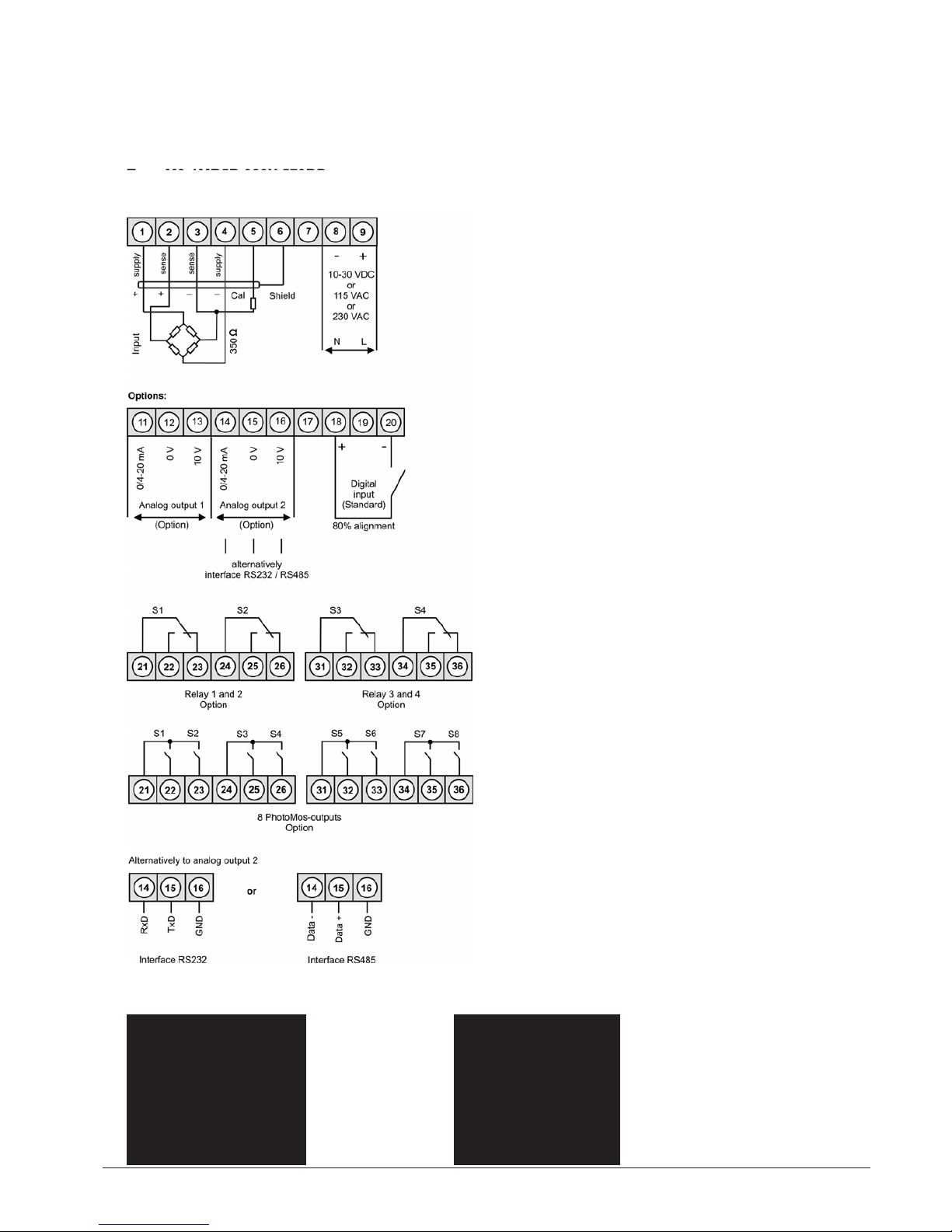
3. Electrical connection
Type M3-1MR5B.020X.470BD supply of 115 VAC
Type M3-1MR5B.020X.570BD supply of 230 VAC
Type M3-1MR5B.020X.670BD supply of 10-30 VDC
DAL-311x9x0S with digital input and external
voltage source
DAL-311x9x0S with digital input in combination
with 24 VDC sensor supply
Type DAL-311x9x0S
Type DAL-311x9x0S
Type DAL-311x9x0S

ACS-CONTROL-SYSTEM GmbH l Lauterbachstr. 57 l D-84307 Eggenfelden l www.acs-controlsystem.de l [email protected] 7
5
4. Function and operation description
4. Function and operation description
Level Key Description
Menu-level
Change to parameterisation level and deposited values.
Keys for up and down navigation in the menu level.
Change into operation mode.
Parameterisation-
level
To confirm the changes made at the parameterization level.
Adjustment of the value / the setting.
Change into menu level or break-off in value input.
Menu-group-level
Change to menu level.
Keys for up and down navigation in the menu group level.
Change into operation mode or back into menu level.
Operation
The operation is divided into three different levels.
Menu level (delivery status)
This level was designed for the standard settings of the device. Only menu items which are sufficent to set
the device into operation are displayed. To get into the professional level, run through the menu level and
parameterise prof under menu item RUN.
Menu group level (complete function volume)
Suited for complex applications as e.g. linkage of alarms, setpoint treatment, totaliser function etc. In this
level function groups which allow an extended parameterisation of the standard settings are availabe. To
leave the menu group level, run through this level and parameterise uloc under menu item RUN.
Parameterisation level:
Parameter deposited in the menu item can here be parameterised. Functions, that can be changed or
adjusted, are always signalised by a flashing of the display. Settings that are made in the parameterisation
level are confirmed with [P] and thus saved. Pressing the [O]-key leads to a break-off of the value input and
to a change into the menu level. All adjustments are saved automatically by the device and changes into
operating mode, if no further key operation is done within the next 10 seconds.

ACS-CONTROL-SYSTEM GmbH l Lauterbachstr. 57 l D-84307 Eggenfelden l www.acs-controlsystem.de l [email protected]
8
6
4. Function and operation description
Function chart:
4.1 Parameterisation software PM-TOOL:
Part of the PM-TOOL are the software on CD and an USB-cable with device adapter. The connection
happens via a 4-pole micromatch-plug on the back side of the device, to the PC-side the connection
happens via an USB plug.
System requirements: PC incl. USB interface
Software: Windows XP, Windows VISTA
With this tool the device configuration can be generated, omitted and saved on the PC. The parameters can
be changed via the easy to handle program surface, whereat the operating mode and the possible selection
options can be preset by the program.
CAUTION!
During parameterisation with connected measuring signal, make sure that the measuring signal has no
mass supply to the programming plug. The programming adapter is galvanic not isolated and directly
connected with the PC. Via polarity of the input signal, a current can discharge via the adapter and destroy
the device as well as other connected components!
ACS-CONTROL-SYSTEM GmbH l Lauterbachstr. 57 l D-84307 Eggenfelden l www.acs-controlsystem.de l [email protected] 9
7
5.1. Switching on
Once the installation is complete, start the device by applying the voltage supply. Before, check once again
that all electrical connections are correct.
Starting sequence
For 1 second during the switching-on process, the segment test (8 8 8 8 8) is displayed followed by an
indication of the software type and, after that, also for 1 second the software version. After the starting
sequence, the device switches to operation/display mode.
5.2. Standard parameterisation: (Flat operation level)
To parameterise the display, press the [P]-key in operating mode for 1 second. The display then changes to
the menu level with the first menu item TYPE.
5. Setting up the device
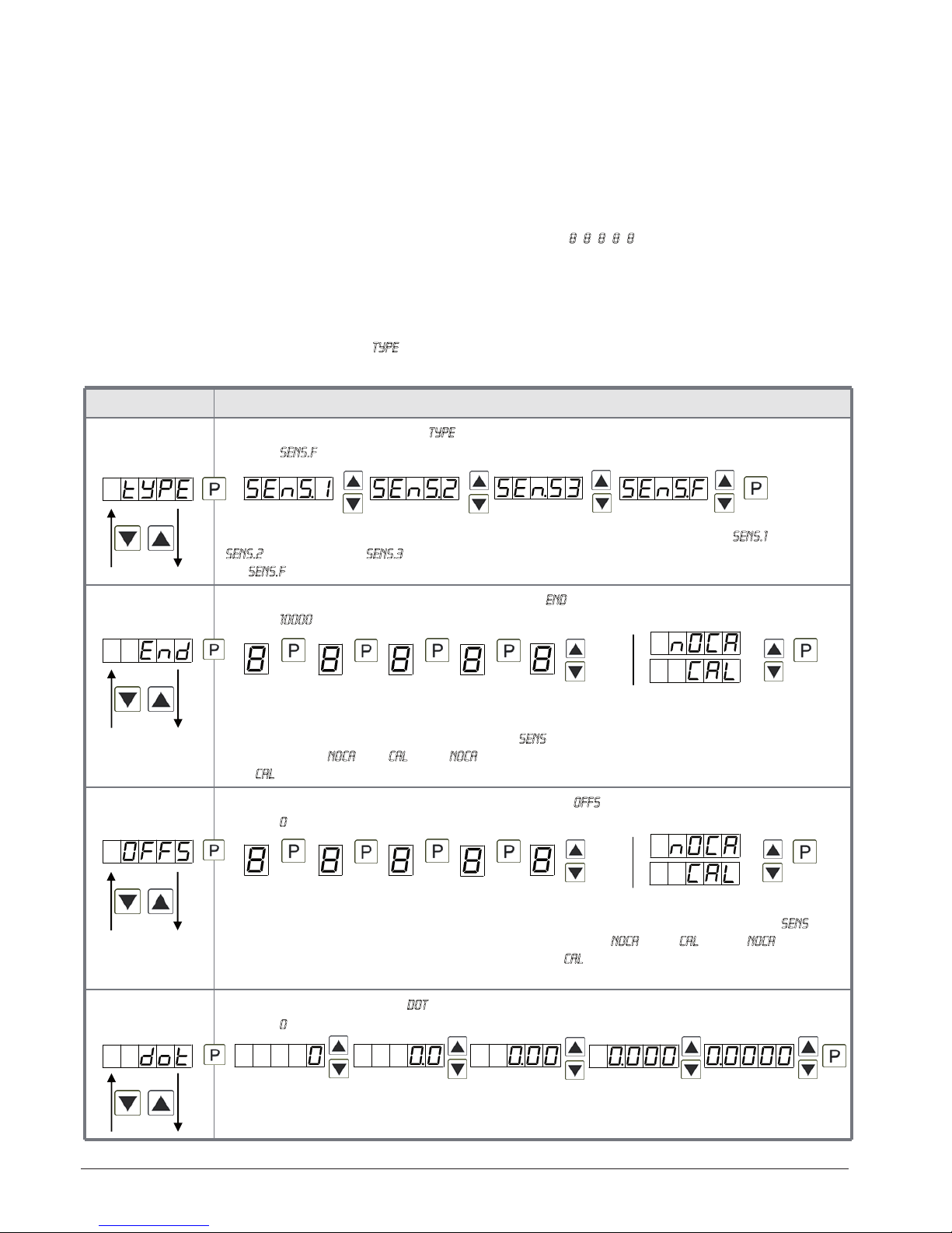
Menu level Parameterisation level
Selection of the input signal, tYPE:
Default: sens.f
There are 3 measuring input options available for known sensor sensibilities: SENS.1 for 1mV/V,
SENS.2 for 2mV/V and SENS.3 for 3.3mV/V. Each sensor is measured and calibrated up to 4mV/V
via SEnS.F. Confirm the selection with [P] and the display switches back to menu level.
Setting the end value of the measuring range, END:
Default: 10000
Set the end value from the smallest to the highest digit with [▲] [▼]and confirm each digit with
[P]. A minus sign can only be parameterized on the highest value digit. After the last digit, the
display switches back to the menu level. If Sens was selected as input option, you can only
select between noca and cal. With noca, only the previously set display value is taken over, and
with cal, the device takes over both the display value and the analogue input value.
Setting up the measuring range start/offset value, offs:
Default: 0
Enter the start/offset value from the smallest to the highest digit with [▲] [▼]and confirm each
digit with [P]. After the last digit the display switches back to the menu level. If Sens was
selected as input option, you can only select between noca and cal. With noca, only the
previously set display value is taken over, and with cal, the device takes over both the display
value and the analogue input value.
Setting the decimal point, dot:
Default: 0
The decimal point on the display can be moved with [▲] [▼]and confirmed with [P]. The
display then switches back to the menu level again.
5. Setting up the device
ACS-CONTROL-SYSTEM GmbH l Lauterbachstr. 57 l D-84307 Eggenfelden l www.acs-controlsystem.de l [email protected]
10
8
5. Setting up the device
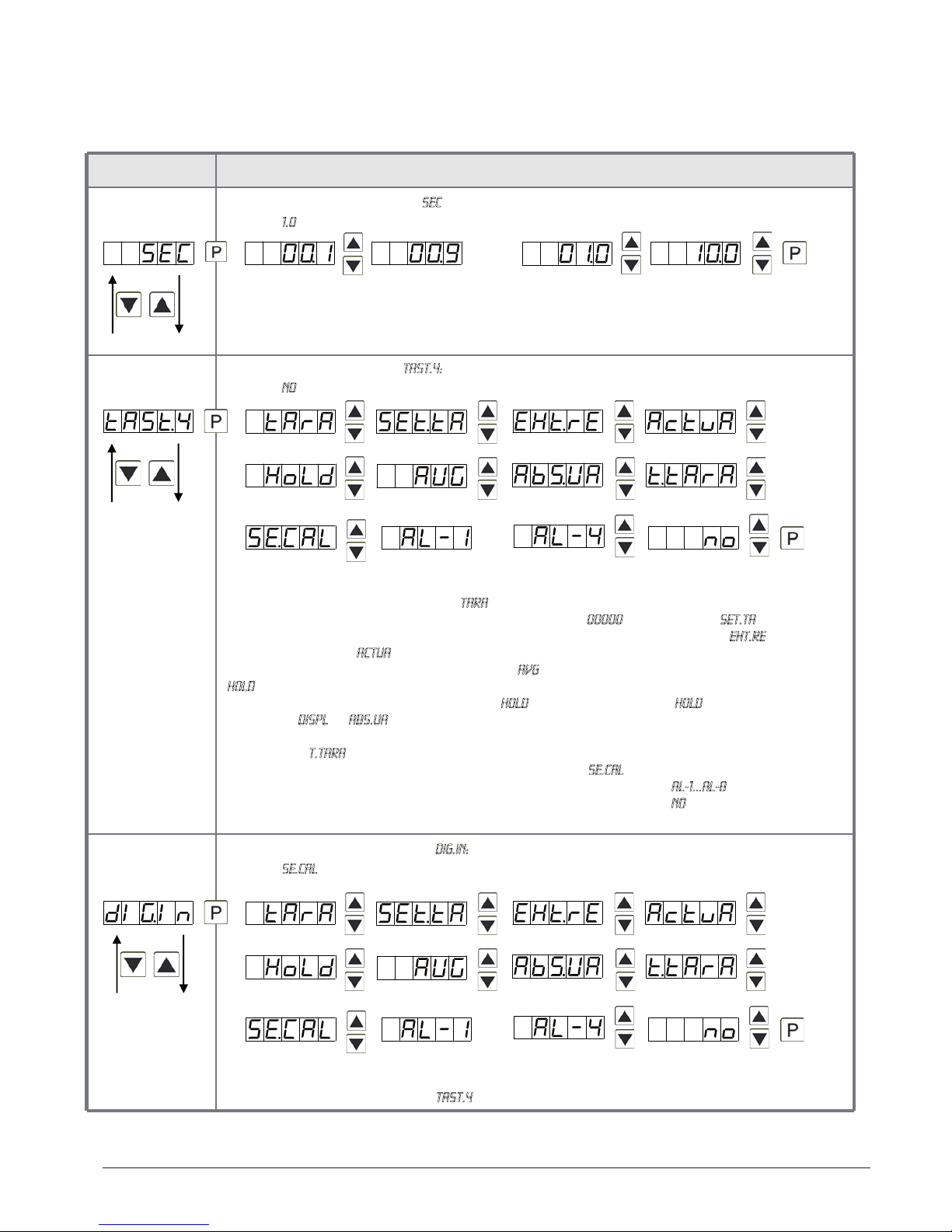
Menu level Parameterisation level
Setting up the display time, SEC:
Default: 1.0
The display time is set with [▲] [▼]. The display moves up in increments of 0.1 up to 1 second
and in increments of 1.0 up to 10.0 seconds. Confirm the selection by pressing the [P] button.
The display then switches back to the menu level again.
Special function [O]-key, tASt.4:
Default: no
For the operation mode, special functions can be deposited on the [O]-key. This function is
activated by pressing the key. With tArA the display is tared to zero und saved permanently as
offset. The device acknowledges the correct taring with oo0oo in the display. Set.tA switches into
the offset value and can thus be changed via the navigation keys [▲] [▼].EHt.rE deletes the
min/max memory. ActuA shows the measurand, then the display changes onto the para-
meterised display value. The same goes for AVG, here the sliding average value is displayed. If
HOLD has been selected, the moment can be hold constant by pressing the [O]-key, and is
updated by releasing the key. Advice: Hold is activated only, if HOLD was selected under
parameter DISPL. If AbS.UA (absolute value) was selected, the display shows the values that have
been measured since the voltage has been connected, without consideration of a previous
taring. With t.tAra (temporarily Tara) the offset is determined by rising shoulder of the digital
input and kept only for the period of the signal. Via SE.CAL a sensor calibration is done by
pushing the zero-key, the flow diagram is shown in chapter 4.4. At AL-1…AL-8 an output can be
set and therewith e.g. a switch of the metering point can be done. If nois selected, the [O]-key
is without any function in the operation mode.
Special function digital input, dIG.In:
Default: se.cal
The above given parameters can be set for the operation mode onto the optional digital input
aswell. See function description tASt.4.
then
…
…
ACS-CONTROL-SYSTEM GmbH l Lauterbachstr. 57 l D-84307 Eggenfelden l www.acs-controlsystem.de l [email protected] 11
9
5. Setting up the device
Menu level Parameterisation level
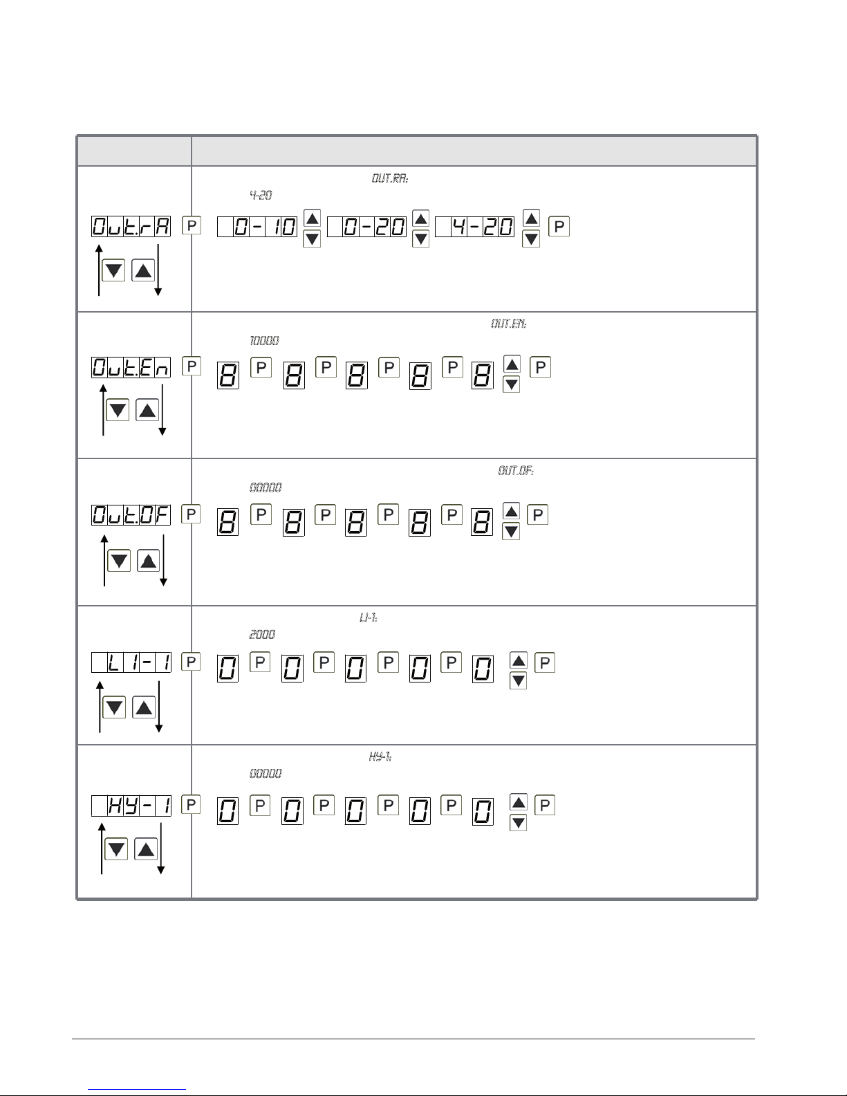
Selection of analog output, Out.rA:
Default: 4-20
Three output signals are available: 0-10 VDC, 0-20 mA and 4-20 mA, with this function, the
demanded signal is selected.
Setting up the final value of the analog output, Out.En:
Default: 10000
The final value is adjusted from the smallest digit to the highest digit with [▲] [▼]and digit by
digit confirmed with [P]. A minus sign can only be parameterised on the highest digit. After the
last digit, the device changes back into menu level.
Setting up the initial value of the analog output, Out.OF:
Default: 00000
The final value is adjusted from the smallest digit to the highest digit with [▲] [▼]and digit by
digit confirmed with [P]. A minus sign can only be parameterised on the highest digit. After the
last digit, the device changes back into menu level.
Threshold values / limits, LI-1:
Default: 2000
This value defines the threshold, that activates/deactivates an alarm.
Hysteresis for limit values, HY-1:
Default: 00000
The delayed reaction of the alarm is the difference to the threshold value, which is defined by
the hysteresis.

ACS-CONTROL-SYSTEM GmbH l Lauterbachstr. 57 l D-84307 Eggenfelden l www.acs-controlsystem.de l [email protected]
12
10
5. Setting up the device
Menu level Parameterisation level
Function for threshold value undercut / exceedance, Fu-1:
Default: high
A limit value undercut is selected with Louu (for LOW = lower limit value), a limit value
exceedance with High (for HIGH = higher limit value). If e.g. limit value 1 is on a threshold level
of 100 and allocated with function High, an alarm is activated by reaching of the threshold level.
If the threshold value was allocated to Low, an alarm will be activated by undercutting the
threshold value, as long as the hysteresis is zero.
The same applies to LI-2 !
User code (4-digit number-combination, free available), U.CodE:
Default: 0000
If this code was set (> 0000), all parameters are locked for the user, if LOC has been selected
before under menu item run. By pressing [P] for 3 seconds in operation mode, the display
shows COde. The U.Code needs to be entered to get to the reduced number of parameter sets.
The code has to be entered befor each parameterisation, until the A.Code (Master code) unlocks
all parameters again.
Master code (4-digit number-combination, free available), A.CodE:
Default: 1234
All parameters can be unlocked with this code, after LOC has been activated under menu item
run. By pressing [P] for 3 seconds in operation mode, the display shows COde and enables the
user to reach all parametes by entering the A.codE. Under run the parameterisation can be
activated permanently by selecting ULOC or ProF, thus at an anew pushing of [P] in operation
mode, the code needs not to be entered again.
5.3. Programming interlock „RUN“
Activation / deactivation of the programming lock or completion of the standard
parameterisation with change into menu group level (complete function range), run:
Default: uloc
Choose between the deactivated key lock Uloc (works setting) and the activated key lock Loc, or
the change into the menu group level ProF with the navigation keys [▲] [▼]. Confirm the
selection with [P]. After this, the display confirms the settings with "-- - - -", and automatically
switches to operating mode. If Loc was selected, the keyboard is locked. To get back into the
menu level, press [P] for 3 seconds in operating mode. Now enter the CODE (works setting 1 2 3
4) that appears using [▲] [▼] plus [P] to unlock the keyboard. FAIL appears if the input is
wrong. To parameterise further functions ProF needs to be set. The device confirms this setting
with „-- - - -„and changes automatically in operation mode. By pressing [P] for approx. 3
seconds in operation mode, the first menu group InP is shown in the display and thus confirms
the change into the extended parameterisation. It stays activated as long as ULOC or LOC is
entered in menu group RUN.
ACS-CONTROL-SYSTEM GmbH l Lauterbachstr. 57 l D-84307 Eggenfelden l www.acs-controlsystem.de l [email protected] 13
11
5. Setting up the device
5.4. Extended parametrisation (Professional operation level)
Menu group level
Menu level
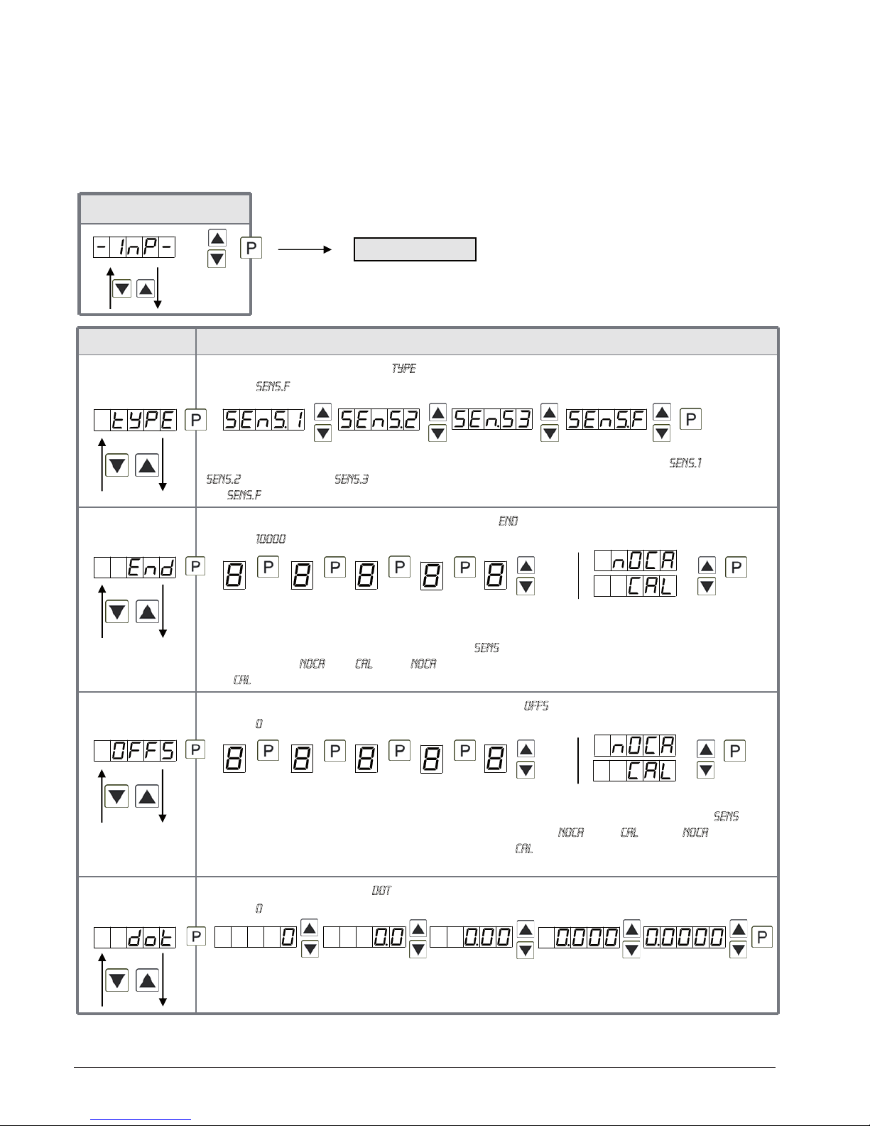
5.4.1. Signal input parameters
Menu level Parameterisation level
Selection of the input signal, tYPE:
Default: sens.f
There are 3 measuring input options available for known sensor sensibilities: SENS.1 for 1mV/V,
SENS.2 for 2mV/V and SENS.3 for 3.3mV/V. Each sensor is measured and calibrated up to 4mV/V
via SEnS.F. Confirm the selection with [P] and the display switches back to menu level.
Setting the end value of the measuring range, END:
Default: 10000
Set the end value from the smallest to the highest digit with [▲] [▼]and confirm each digit with
[P]. A minus sign can only be parameterized on the highest value digit. After the last digit, the
display switches back to the menu level. If Sens was selected as input option, you can only
select between noca and cal. With noca, only the previously set display value is taken over, and
with cal, the device takes over both the display value and the analogue input value.
Setting up the measuring range start/offset value, offs:
Default: 0
Enter the start/offset value from the smallest to the highest digit with [▲] [▼]and confirm each
digit with [P]. After the last digit the display switches back to the menu level. If Sens was
selected as input option, you can only select between noca and cal. With noca, only the
previously set display value is taken over, and with cal, the device takes over both the display
value and the analogue input value.
Setting the decimal point, dot:
Default: 0
The decimal point on the display can be moved with [▲] [▼]and confirmed with [P]. The
display then switches back to the menu level again.

ACS-CONTROL-SYSTEM GmbH l Lauterbachstr. 57 l D-84307 Eggenfelden l www.acs-controlsystem.de l [email protected]
14
5. Setting up the device
12
Menu level Parameterisation level
Setting up the display time, SEC:
Default: 1.0
The display time is set with [▲] [▼]. The display moves up in increments of 0.1 up to 1 second
and in increments of 1.0 up to 10.0 seconds. Confirm the selection by pressing the [P] button.
The display then switches back to the menu level again.
Rescaling the measuring input values, EndA:
Default: 10000
With this function, you can rescale the input value of e.g. 1.1 mV/V (works setting) without
applying a measuring signal. If sensor calibration has been selected, these parameters are not
available.
Rescaling the measuring input values, OFFA:
Default: 0
With this function, you can rescale the input value of e.g. 3.5 mA (works setting) without
applying a measuring signal. If sensor calibration has been selected, these parameters are not
available.
Setting up the tare/offset value, tArA:
Default: 0
The given value is added to the linearized value. In this way, the characteristic line can be
shifted by the selected amount.
Setting up the balance point, Adj.pt:
Default: 80.00
The balance point is preset to 80%. Assume an 80% detuning while switching the alignment
relay during an automatic sensor alignment. This value can be freely adjusted.
Setting up the physical unit, UnIt:
Default: no
One can choose between the above shown physical units. It will be displayed on the 5th digit of
the display.
then
ACS-CONTROL-SYSTEM GmbH l Lauterbachstr. 57 l D-84307 Eggenfelden l www.acs-controlsystem.de l [email protected] 15
13
5. Setting up the device
Menu level Parameterisation level
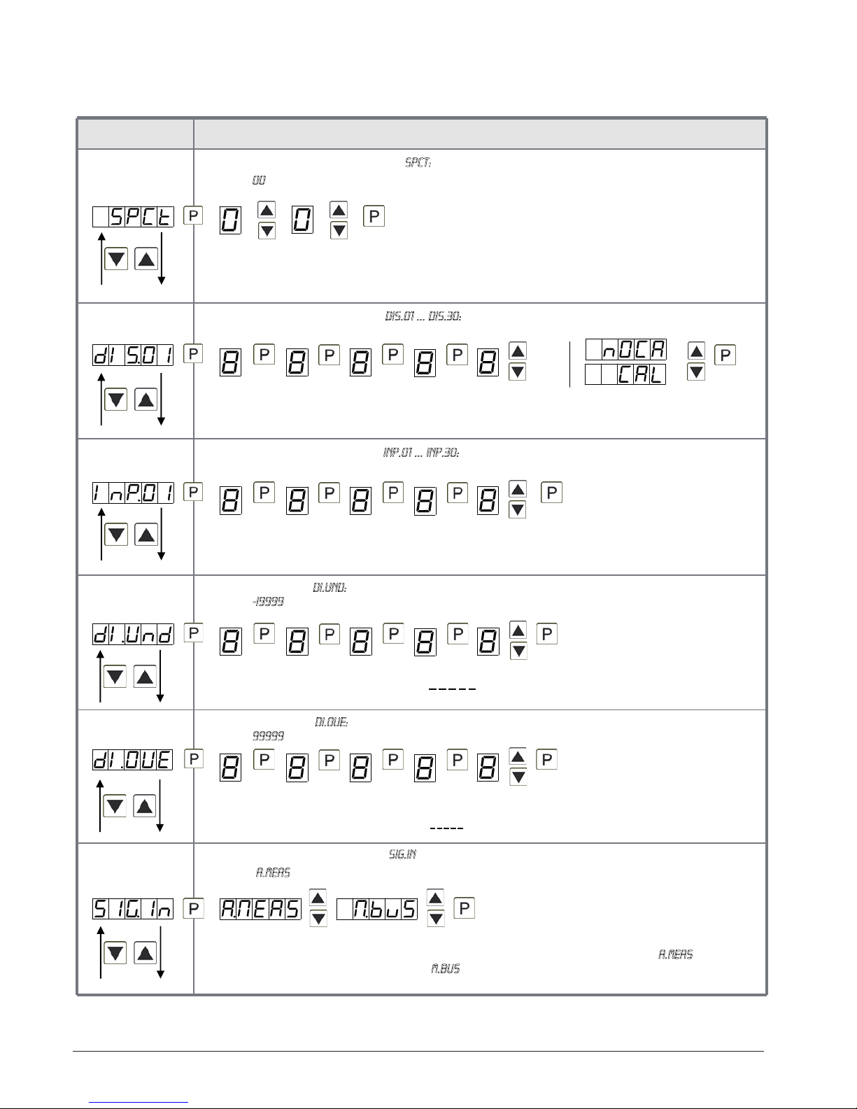
Number of additional setpoints, SPCt:
Default: 00
30 additional setpoints can be defined to the initial value and final value, so linear sensor
values are not linearised. Only activated setpoint parameters are displayed.
Display values for setpoints, dIS.01 … dIS.30:
Under this parameter setpoints are defined according to their value. At the sensor calibration,
like at final value / offset, one is asked at the end if a calibration shall be activated.
Analog values for setpoints, InP.01 … InP.30:
The setpoints are always set according to the selected input signal. The desired analog values
can be freely parameterised in ascending order.
Device undercut, dI.Und:
Default: -i9999
With this function the device undercut (_ _ _ _ _) can be defined on a definite value. Exception is
input type 4-20 mA, it already shows undercut at a signal <1 mA, so a sensor failure is marked.
Display overflow, dI.OUE:
Default: 99999
With this function the display overflow (_ _ _ _ _) can be defined on a definite value.
Input variable of process value, SIG.in:
Default: a.meas
With this parameter, the device can be controlled via the analog input signals a.meas = mV/V or
via the digital signals of the interface M.bus = RS232/RS485 (modbus protocol). With [P] the
selection is confirmed and the device changes into menu level.

ACS-CONTROL-SYSTEM GmbH l Lauterbachstr. 57 l D-84307 Eggenfelden l www.acs-controlsystem.de l [email protected]
16
14
5. Setting up the device
Menu level Parameterisation level
Back to menu group level, rEt:
With [P] the selection is confirmed and the device changes into menu group level „–INP–“.
5.4.2. General device parameters
Menu level Parameterisation level
Display time, DISEC:
Default: 01.0
The display is set up with [▲] [▼]. Thereby it switches up to 1 second in increments of 0.1
seconds and up to 10.0 seconds in increments of 1.0. With [P] the selection is confirmed and
the device changes into menu level.
Rounding of display values, round:
Default: 00001
This function is for instable display values, where the display value is changed in
increments of 1, 5, 10 or 50. This does not affect the resolution of the optional outputs. With [P]
the selection is confirmed and the device changes into menu level.
Arithmetic, ArItH:
Default: n0
With this function the calculated value, not the measuring value, is shown in the display. With
no, no calculation is deposited. With [P] the selection is confirmed and the device changes into
menu level.
Sliding average determination, AVG:
Default: 1.0
Here, the number of the meterings that need to be averaged is preset. The time of averaging
results of the product of measuring time SEC and the averaged metering AVG. With the selection
of AVG in the menu level DISPL, the result will be shown in the display and evaluated via the
alarms.
Menu group level
Menu level
then
Reciprocal Root
extraction
Square
ACS-CONTROL-SYSTEM GmbH l Lauterbachstr. 57 l D-84307 Eggenfelden l www.acs-controlsystem.de l [email protected] 17
5. Setting up the device
15
Menu level Parameterisation level
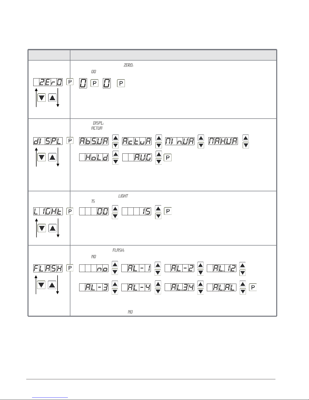
Zero point slowdown, ZErO:
Default: 00
At the zero point slowdown, a value range around the zero point can be preset, so the display
shows a zero. If e.g. a 10 is set, the display would show a zero in the value range from -10 to
+10; below continue with -11 and beyond with +11. The maximum adjustable range of value is
99.
Display, dISPL:
Default: actua
With this function the current measuring value, the min/max-value, the totaliser, the process-
controlled hold-value, the sliding average value, the constant value or the difference between
constant value and current value can be allocated to the display. With [P] the selection is
confirmed and the device changes into menu level.
Brightness control, Light:
Default: 15
The brightness of the display can be adjusted in 16 levels from 00 = very dark to 15 = very
bright via this parameter or alternatively via the navigation keys from the outside. During the
start of the device the level that is deposited under this parameter will always be used, even
though the brightness has been changed via the navigation keys in the meantime.
Display flashing, FLASH:
Default: no
A display flashing can be added as additional alarm function either to single or to a combination
of off-limit condition. With no, no flashing is allocated.

ACS-CONTROL-SYSTEM GmbH l Lauterbachstr. 57 l D-84307 Eggenfelden l www.acs-controlsystem.de l [email protected]
18
5. Setting up the device
16
Menu level Parameterisation level
Assignment (deposit) of key functions, tASt:
Default: no
For the operation mode, special functions can be deposited on the navigation keys [▲] [▼], in
particular this function is made for devices in housing size 48x24mm which do not have a 4th
key ([O]-key). If the min/max-memory is activated with EHtr, all measured min/max-values are
saved during operation and can be recalled via the navigation keys. The values get lost by
restart of the device. If the threshold value correction LI.12 or LI.34 was choosen, the values of the
threshold can be changed during operation without disturbing the operating procedure. With
tArA the device is tared to zero and saved permanently as offset. The device confirms the
correct taring by showing ooooo in the display. Set.tA switches into the offset value and can be
changed via the navigation keys [▲] [▼]. The configuration of EHt.rE deletes the min/max-
memory. Under ActuA the current measurand is shown (by pushing the button) and under Abs.ua
the absolute value is displayed. If AbS.UA (absolute value) was selected, the display shows the
value that has been measured since voltage connection, without consideration of a previous
taring. If nois selected, the navigation keys are without any function in the operation mode.
Special function [O]-key, tASt.4:
Default: no
For the operation mode, special functions can laid be on the [O]-key. This function is triggered
by pushing the key. With tArA the display is tared to zero and is saved permanently as offset.
The display confirms the correct taring by showing ooooo in the display. Set.tA switches into the
offset value and can be changed via the direction keys [▲] [▼].EHt.rE deletes the min/max-
memory. ActuA shows the measuring value. Then the display switches to the parameterised
display value. The same goes for AVG, here the sliding average value is displayed. At selected
HOLD the instant value is held by pushing the [O]-key and updated by releasing the key.
Advice: Hold can only be activated if HOLD was selected under parameter DISPL. If AbS.UA
(absolute value) was selected, the display shows the values that have been measured since
the voltage has been connected, without consideration of a previous taring. With t.tAra
(temporarily Tara) the offset is determined by rising shoulder of the digital input and kept only
for the period of the signal. Via SE.CAL a sensor calibration is done by pushing the zero-key, the
flow diagram is shown in chapter 4.4. At AL-1…AL-8 an output can be set and therewith e.g. a
switch of the metering point can be done. If nois selected, the [O]-key has no function in the
operation mode.
…

ACS-CONTROL-SYSTEM GmbH l Lauterbachstr. 57 l D-84307 Eggenfelden l www.acs-controlsystem.de l [email protected] 19
5. Setting up the device
17
Menu level Parameterisation level
Special function digital input, dIG.In:
Default: no
For the operation mode, the above shown parameters can be laid on the optional digital input,
too. Functions description see tASt.4.
Back to menu group level, rEt:
With [P] the selection is confirmed and the device changes into menu group level „–fct–“.
…
Menu level Parameterisation level
User code U.Code:
Default: 0000
Via this code reduced sets of parameters can be set free. A change of the U.CodE can be done
via the correct input of the A.CodE (master code).
Master code, A.Code:
Default: 1234
By entering A.CodE the device will be unlocked and all parameters are released.
Menu group level
5.4.3. Safety parameters
Menu level
ACS-CONTROL-SYSTEM GmbH l Lauterbachstr. 57 l D-84307 Eggenfelden l www.acs-controlsystem.de l [email protected]
20
5. Setting up the device
18
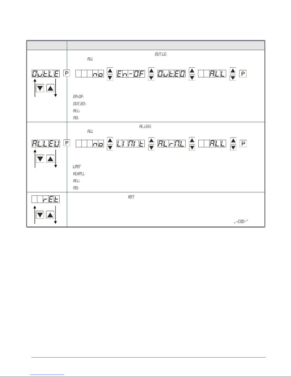
Menu level Parameterisation level
Release/lock analog output parameter, Out.LE:
Default: all
Analog output parameter can be locked or released for the user:
-En-oF: the initial or final value can be changed in operation mode
-Out.EO-. the output signal can be changed from e.g. 0-20 mA to 4-20 mA or 0-10 VDC
-ALL: analog output parameters are released
-no: all analog output parameters are locked
Release/lock alarm parameters, AL.LEU:
Default: all
This parameter describes the user release/user lock of the alarm.
- LIMIt: here only the range of value of the threshold values 1-4 can be changed
-ALrM.L: here the range of value and the alarm trigger can be changed
-ALL: all alarm parameters are released
-no: all alarm parameters are locked
Back to menu group level, rEt:
With [P] the selection is confirmed and the device changes into menu group level „–COD–“.
Table of contents
Popular Amplifier manuals by other brands


Rockville
Rockville RCS650-6 owner's manual

Televes
Televes 4509 Safety instructions

Marantz
Marantz PM10s1 owner's manual

Studiomaster Professional
Studiomaster Professional PA Series owner's manual

Phontech Communication
Phontech Communication Argo A-1 Handbook

Audio Note
Audio Note SORO Phono SE Signature Owner's Information


