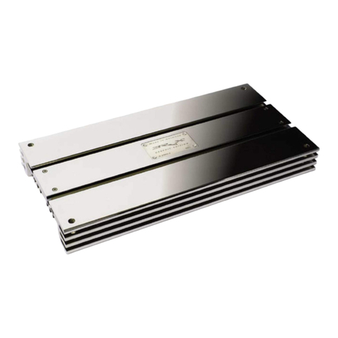
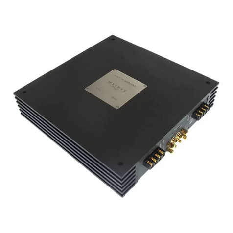
BRAX NOX4 DSP User manual

NOX4 DSP
Bedienungsanleitung
Instruction Manual

17
&RQJUDWXODWLRQVRQ\RXUSXUFKDVHRIWKLVKLJKTXDOLW\%5$;DPSOL¿HU
:LWKWKHDPSOL¿HU%5$;12;'63\RXKDYHFKRVHQDSURGXFWZKLFKFRPELQHVXOWLPDWHSHUIHFWLRQLQVRXQGDQGWHFKQLFDO
PDWXULW\ZLWKDPD[LPXPRILQGLYLGXDOLW\2QO\KDQGVHOHFWHGFRPSRQHQWVDQG¿QHVWPDWHULDOVDUHXVHGLQWKHDPSOL¿HUµV
production process and thus guarantee a top-class high-end music experience.
For more than 30 years we have been working on the development and manufacturing of top-notch audio components. By
QRZWKHEUDQG%5$;KDVJDLQHGZRUOGZLGHUHSXWDWLRQIRUEHLQJVXSHULRUTXDOLW\9DULRXVKRQRXUVE\WKHZRUOGµVPDMRUFDU
audio magazines and, last but not least, numerous world wide innovation awards give proof of our excellent work.
:HKDYHSURYLGHGWKHDPSOL¿HU%5$;12;'63ZLWKHYHU\WKLQJLWUHTXLUHVLQRUGHUWRVHWQHZVWDQGDUGVFRQFHUQLQJ
sound quality, manufacturing, and longevity. We are proud to offer you this high-end product MADE IN GERMANY.
We wish you many hours of enjoyment with your BRAX NOX4 DSP.
AUDIOTEC FISCHER GMBH
Heinz Fischer
Founder und Managing Director
DEAR CUSTOMER
<RXUDPSOL¿HU%5$;12;'63KDVWKHVHULDOQXPEHU

18
%DVHGRQRXUEDVLFSULQFLSOHV³KDQGPDGH´DQG³PDGHLQ*HUPDQ\´WKHWDUJHWLVWRFUHDWHUHIHUHQFHFODVVKLJKHQGDPSOL¿HUV
without compromisses according to the latest technical knowledge. The NOX4 and NOX4 DSP are the results of outstanding
achievments as well as real high end statements. A long lasting period of research and development, innovative technologies
and an extremely fastidious manufacturing combined with the love for music as the driving force for our work make the BRAX
12;VHULHVGRXEWOHVVO\WRWKHEHVWVRXQGLQJFKDQQHODPSOL¿HURIWKHZRUOG
&RQFHUQLQJWKHVWUDLJKWGHVLJQRIWKH12;DPSOL¿HUVDQGWKHVRSKLVWLFDWHGOD\RXWRIWKHFLUFXLWERDUGZHKDYHGHYHORSHG
WZRGLIIHUHQWPRGHOV7KH12;LVPDGHZLWKRXWFURVVRYHUVDQG¿OWHUVHFWLRQV6KRUWVLJQDOSDWKVFRPELQHGZLWKVHOHFWHG
components “made in Germany” ensure pristine listening pleasure and underline the puristical high-end philosophy of BRAX.
The extended version NOX4 DSP provides an wide adjustment range via the integrated 6-channel Audio-DSP. It allows not
RQO\WRFRQ¿JXUHWKHIRXULQWHUQDOFKDQQHOVEXWDOVRWKHWZR/LQH2XWSXWV
In order to completely eliminate power differences and manufacturing tolerances, we only use hand-selected transistors for
WKHSURGXFWLRQRIHDFK12;DPSOL¿HU&RQFHUQLQJSRZHUYROWDJHDQGUHVLVWDQFHGDWDZHVHOHFWWKHPLQPRUHWKDQ
FDWHJRULHV7KXVDOOWUDQVLVWRUVKDUPRQL]HSHUIHFWO\LQWHUPVRIWHFKQLFDOVSHFL¿FDWLRQV,QGRLQJVRRXU%5$;DPSOL¿HUV
obtain a worldwide reference status.
The switching power supply of the BRAX NOX4 DSP is a combination of state-of-the-art technology and precisely selected
FRPSRQHQWV,Q RUGHU WRFRQWUROYROWDJHÀXFWXDWLRQVDQ H[WHUQDO SRZHUVWDELOL]HUFDQGLUHFWO\EH FRQQHFWHG WRWKHSRZHU
supply. Moreover, the solid and gold-plated terminals for cables up to 50mm² make another contribution to an ideal power
VXSSO\RIWKH%5$;12;DPSOL¿HUV
$WWKHHQGRIWKHGD\WKH%5$;12;'63FDQEHGHVFULEHGDVDQDPSOL¿HUZLWKDVRXQGUHQGLWLRQWKDWLVKLJKO\G\QDPLF
powerful and swift as an arrow. The underlying philosophy is topped-off by a packaging in an exclusive wooden box. Further-
PRUHHDFKVLQJOHDPSOL¿HULVPDQXIDFWXUHGLQGLYLGXDOO\DQGLWVUHVSHFWLYHVHULDOQXPEHULVUHFRUGHGLQRXUGDWDEDVH7KH
DPSOL¿HU%5$;12;'63LVRQO\SURGXFHGRQGHPDQGDQGRIFRXUVHZHFDQUHVSRQGWRRXUFXVWRPHU¶VUHTXLUHPHQWV,Q
WKLVZD\HDFKDPSOL¿HULVDYDOXDEOHLQGLYLGXDOLWHPWKDWULJKWO\GHVHUYHVWKHWLWOH³KLJKHQGPDGHLQ*HUPDQ\´
THE BRAX PHILOSOPHY

78
Speaker terminals channel A - D
USB-Port
7
8
9
9
MicroSD card reader
10
11 12 13 7
14 14
Signal inputs channel A - D
Control Input
11
12
13 Optical Input
10 Control-Pushbutton & Status-LED 14 Signal outputs channel E and F
19
CONNECTION AND CONTROL ELEMENTS
54
Connection remote lead
Connection battery cable
CPS - Colour Protection System
Connection ground cable
1 2 3
1
2
3
4
5Connection BRAX Power Stabilizer (plus)
6
6Connection BRAX Power Stabilizer (minus)

20
1
1
1
1
3
259
7
8
6 6
17
10
13
13
18
18
21
22
5
10
12 12
12 12
4
11
19
19
20
20
14 1615 1616

THE DESIGN OF THE AMPLIFIER
21
1Ultra-low internal resistance due to solid gold-pla-
ted terminals; for power cables up to 50 mm² and
speaker cables up to 6 mm²
2External connection for BRAX-Power-Stabilizers
directly connected to the switching transistors gu-
DUDQWHH H[FHSWLRQDO KLJK HI¿FLHQF\ DQG RSWLPXP
power stabilization
3Interference-free power supply due to optimized
suppression coil up to 150 A with ultra-low internal
resistance
4Four Mini-Blade fuses in parallel (4 x 25 A) in order
to minimize the internal resistance
5Six capacitors, each with 5.000 μF (in total 30.000
μF), take care of an extremely high current impulse
load. Especially designed capacitors with 8-times-
contacted wound foil minimize the internal resi-
stance
6200 A high-performance switching transistors.
7+LJK HI¿FLHQF\ GXH WR VXSHUIDVW 6FKRWWN\SRZHU
diodes with more than 160 A in total
8 2SWLPXPSRZHUVXSSO\ RI WKH DPSOL¿HU WUDQVLVWRUV
due to newly developed storage coils that bridge
the switching delay dead times
9 6SHFLDOGHYHORSHGWUDQVIRUPHUVZLWKKLJKO\HI¿FLHQW
core materials guarantee a total performance of
more than 1.200 Watts
10 Optimum power supply of the transistors due to four
8-times-contacted low-impedance capacitors with a
total capacity of 15.600 μF.
11 Separate switching power supply for the supply
voltage of the DSP-PCB (NOX4 DSP).
12 Best signal processing due to a newly developed
and discretely designed driver.
13 16 handselected high-end MOSFET transistors
which account for brilliant sound.
14 High-end BurrBrown 2-channel D/A signal con-
verter (3 x 2-channel) for best possible signal
conversion
15 +LJK(QG $XGLR'63 ZLWK IUHHO\ FRQ¿JXUDEOH
channels
16 High-End Asahi Kasei A/D converts for a lossless
signal conversion of the analog signal
17 Processor-controlled adjustment of the input sen-
sitivity via special digital-controlled level control-
ler.
18 Siemens high-current relays with Degussa-
contacts account for the internal and external
SURWHFWLRQRIWKHDPSOL¿HU
19 Reed-relais for a distortion-free turn-on and turn-
off of the DSP controlled Line-Outputs E and F
(NOX4 DSP)
20 5&$OLQHRXWSXWVIRUFRQQHFWLQJDQRWKHUDPSOL¿HU
7KHVH RXWSXWV FDQ EH IUHHO\ FRQ¿JXUHG YLD WKH
DSP
21 Gold-plated RCA (cinch) inputs and outputs gua-
rantee an interference-free signal transmission.
22 The solid heatsink, made of a special aluminium
alloy takes care of a perfect cooling of power sup-
SO\WUDQVLVWRUVDQGWKRVHRIWKHDPSOL¿HU

In order to maintain the quality of this product and to ensure safe operation, we strongly recommend that our am-
SOL¿HUVVKRXOGEHLQVWDOOHGE\DQDXWKRUL]HG%5$;GHDOHU7KHLQVWDOODWLRQE\DTXDOL¿HGDQGDFFUHGLWHGLQVWDOOHU
will qualify you for our special lifetime warranty. Your BRAX-dealer will also assist you in selecting the correct
additional components and in ensuring that proper consideration is given to all the safety and sound related
aspects.
*HQHUDOLQVWUXFWLRQV,QVWDOODWLRQRI%5$;DPSOL¿HUV
7R¿QGRXWKRZ%5$;12;'63ZRUNVEHVWIRU\RXUHDGWKLVPDQXDOFDUHIXOO\DQGIROORZWKHLQVWUXFWLRQVIRULQVWDOODWLRQ
We guarantee that this product has been checked for proper functioning before shipping. Before you start installation, dis-
connect the car battery at the minus pole. Once again we would like to urge you to have the installation work carried out by
DVSHFLDOLVWDVDYHUL¿FDWLRQRIFRUUHFWLQVWDOODWLRQDQGFRQQHFWLRQRIWKHXQLWLVDSUHUHTXLVLWHIRUZDUUDQW\FRYHURI%5$;
by AUDIOTEC FISCHER Germany.
,QVWDOO\RXUDPSOL¿HUDWDGU\ORFDWLRQLQWKHFDUZKHUHWKHUHLVVXI¿FLHQWDLUFLUFXODWLRQWRHQVXUHDGHTXDWHFRROLQJRI
WKHHTXLSPHQW$OVRHQVXUHWKDWWKHUHLVVXI¿FLHQWFOHDUDQFHDYDLODEOHIRUPDNLQJWKHFDEOHFRQQHFWLRQVDQGRSHUDWLQJWKH
controls.
)RUVDIHW\UHDVRQVWKHDPSOL¿HUPXVWEHVHFXUHGLQDSURIHVVLRQDOPDQQHU7KLVLVSHUIRUPHGE\PHDQVRIIRXU¿[LQJ
screws screwed into a mounting surface. Before drilling the holes for the screws, carefully examine the area around the
installation position and make sure that there are no electrical cables or components, hydraulic brake lines or any part of
the petrol tank located behind the mounting surface - otherwise these could be damaged. You should be aware of the fact
that such components may also be concealed in the double-skin trim panels/mouldings.
*HQHUDOLQVWUXFWLRQV&RQQHFWLRQRI%5$;DPSOL¿HUV
7KHDPSOL¿HUPD\RQO\EHLQVWDOOHGLQPRWRUYHKLFOHVZKLFKKDYHD9QHJDWLYHWHUPLQDOFRQQHFWHGWRWKHFKDVVLVJURXQG
$Q\RWKHUV\VWHPFRXOGFDXVHGDPDJHWRWKHDPSOL¿HUDQGWKHHOHFWULFDOV\VWHPRIWKHYHKLFOHThe positive lead from the
battery for the complete system should be provided with a line fuse at a distance of max. 30 cm from the battery. The am-
perage rating of the fuse is calculated from the maximum total current input of the car/vehicle audio system.
INITIAL SETUP
22

Never bridge fuses or replace them with fuses with a higher amperage rating as such actions can destroy both of
WKHDPSOL¿HUDQGWKHHQWLUHHOHFWULFDOV\VWHPRIWKHYHKLFOH
Install the cabling in a manner which preludes any danger of the leads being exposed to shear, crushing or rupture forces.
If there are sharp edges in the vicinity (e.g. holes in the body work), all cables must be cushioned and protected to prevent
IUD\LQJ1HYHUOD\WKHSRZHUVXSSO\FDEOHVDGMDFHQWWROHDGVDQGOLQHVFRQQHFWLQJRWKHUYHKLFOHHTXLSPHQWIDQPRWRUV¿UH
detection modules, gas/petrol lines etc.). In order to ensure safe installation, use only high-quality connection materials.
As an aid to calculating the cross-sectional requirements of power cables which are not longer than 5 m, we recommend
PD[$SHUPPð)RUWKHDPSOL¿HU%5$;12;'63ZHVXJJHVWDPLQLPXPFURVVVHFWLRQRIPPðIRUWKHSRVLWLYH
12-volt supply lead and for the ground (chassis) cable. The remote lead should have a cross section of at least 1 mm². In
order to ensure the ideal sound quality and a distortion-free music rendition, please make sure that all cables are securely
¿[HGLQWKHUHVSHFWLYHWHUPLQDOV
Connection of the power supply
1 Connecting the remote lead
The remote lead is connected to the automatic antenna (aerial positive) or remote output of the head unit (radio). This is
RQO\DFWLYDWHGLIWKHKHDGXQLWLVVZLWFKHG217KXVWKHDPSOL¿HULVVZLWFKHGRQDQGRIIZLWKWKHKHDGXQLW
2 Connecting the battery cable
Connect the +12 V power cable to the positive terminal of the battery. Recommended cross section: min. 25 mm².
3 Connecting the ground cable
The ground cable should be connected to a central ground reference point (this is located where the negative terminal of
the battery is grounded at the metal body of the vehicle), or to a bright bare-metal location on the vehicle chassis, i.e. an
area which has been cleaned of all paint residues.
23

4 CPS - Colour Protection System
7KH/('VVKRZWKHRSHUDWLRQVWDWXVRIWKHDPSOL¿HU<HOORZ PDOIXQFWLRQVKRUWFLUFXLWDWVSHDNHURXWSXW
Red (12) = overheated: If the amp shuts off due to overheating it will take some time (depending on the outside tempera-
ture) until it turns on again.
5-6 Connectors for a BRAX Power Stabilizer
If a BRAX Power Stabilizer is connected to this terminal peak loads in the power supply will be eliminated. Thus, the am-
SOL¿HUKDVDOZD\VHQRXJKSRZHUIRULWVSHUIHFWSHUIRUPDQFH
Equipment and control units
7 Loudspeaker terminals
To connect the speaker cables. Never connect the loudspeaker cables with the car chassis ground. It damages your
DPSOL¿HU All speaker systems must be connected in-phase, it means plus to plus and minus to minus. Inverting plus and
minus will result in the loss of bass rendition. The positive terminal is marked on most speakers.
8 USB-Port
7KLVPLQL86%LQSXWLVXVHGWRFRQQHFWDFRPSXWHUZLWKWKHVXSSOLHG86%FDEOH7KH'63FDQEHIUHHO\FRQ¿JXUHGYLDWKLV
USB port and the PC-Tool software.
9 MicroSD card reader
7KH0LFUR6'FDUGUHDGHUFDQEHXVHGWRGRZQORDG¿UPZDUHDQGVRIWZDUHXSGDWHVDVZHOODVFRPSOHWH'63VHWXS¿OHV
containing all DSP settings. The seWXS¿OHLVFRSLHGDXWRPDWLFDOO\WRWKH12;'63ZKHQWKHFDUGµVLQVHUWHG&RS\LQJLV
VKRZQE\WKH6WDWXV/('EOLQNLQJUHGZKHQLWUHYHUWVWRJUHHQRURUDQJHFRS\LQJKDVEHHQFRPSOHWHG2QFHWKH¿OH
has been copied the card must be removed.
Attention: Do not remove the MicroSD card during copying.
7KH12;'63FDQKDQGOHWZRGLIIHUHQWVHWXS¿OHV7KHVH¿OHVKDYH³DI´³DF´³DI´RU³DF´VXI¿[HV8VHWKHFRQWURO
button (10) to toggle between them.
Please note:2QO\RQH³DI´RU³DI´VHWXS¿OHPD\EHRQWKHFDUG)LUPDQGVRIWZDUHXSGDWHVDUHDYDLODEOHIURPZZZ
DXGLRWHF¿VFKHUFRPRUZZZKHOL[KL¿FRP86
24

10 Control pushbutton & Status-LED
7KHFRQWUROSXVKEXWWRQDOORZVWKHXVHUWRVZLWFKEHWZHHQWZRORDGHGVHWXSSUR¿OHVÄDI³DQGÄDI³7RVZLWFKEHWZHHQWKH
VHWXSVWKHEXWWRQPXVWEHSUHVVHGDQGKHOGIRUVHFRQG6ZLWFKLQJLVLQGLFDWHGE\DVLQJXODUUHGÀDVKRIWKH6WDWXV/('
3UHVVLQJWKHEXWWRQIRUVHFRQGVFRPSOHWHO\HUDVHVWKHLQWHUQDOPHPRU\7KLVLVLQGLFDWHGE\DFRQVWDQWÀDVKLQJRIWKH
Status-LED.
Attention: After erasing the setups from memory the NOX4 DSP will not reproduce any audio output.
3OHDVHQRWH7KH12;'63LVGHOLYHUHGLQIDFWRU\PRGHZLWKWZRLGHQWLFDOVHWXS¿OHVZKLFKGLIIHURQO\LQWKHLUH[WHQVLRQV
The Status-LED indicates the current active DSP-setup. Green means that setup 1 (af1) is loaded, orange means
WKDW VHWXS DI LV ORDGHG$ ÀDVKLQJ UHG OLJKW FRXOG LQGLFDWH WKH IROORZLQJ PRGHV 7KH LQWHUQDO PHPRU\ LV HPSW\
2. A connection to a computer is established 3. An upload via a MicroSD card is in progress
11 Signal inputs
7KHDPSOL¿HUKDV5&$FRQQHFWRUVIRU5&$FDEOHVWKDWFDQEHFRQQHFWHGZLWKWKHSUHDPSOL¿HURXWSXWVRIDKHDGXQLWRU
SUHDPSOL¿HU7KHFRQQHFWRUVDUHJROGSODWHGWRHQVXUHDEHWWHUVLJQDOWUDQVPLVVLRQ
3OHDVHQRWHWKDWEULGJHGFKDQQHOVPXVWEHFRQ¿JXUHGLGHQWLFDOO\LQWKHFKDQQHOURXWLQJPDWUL[DQGDVZHOOLQWKH(4VHF-
tion. The appropriate signal input must be routed to both output channels (channel „A & B“ or „C & D“). We recommend to
OLQNWKHEULGJHGFKDQQHOVGXULQJWKHFRQ¿JXUDWLRQLQRXU3&7RROVRIWZDUH
12 Control Input
This multifunctional input is used to connect DSP accessories, like a level remote control or a bluetooth module.
13 Optical Input
Optical input in SPDIF format for connection to signal sources with a digital audio output. The sampling rate of this input
must be between 6 and 192 kHz. The input signal is automatically adjusted to the internal sampling rate.
14 Signal outputs channel E and F
7KHVHSUHDPSOL¿HURXWSXWVDUHXVHGWRFRQQHFWDQRWKHUDPSOL¿HU7KHVLJQDORXWSXWVFDQEHIUHHO\FRQ¿JXUHGLQWKH'63
via the PC-Tool software as at the internal channels. The output voltage is max. 6 Volts RMS.
25

7R FRQ¿JXUH WKH VLJQDO SURFHVVRU PDQXDOO\ WKH 12; '63 PXVW EH FRQQHFWHG WR WKH FRPSXWHU E\ XVLQJ WKH
supplied USB cable. The current PC Tool version is always on our homepage ZZZDXGLRWHFÀVFKHU
FRP 7KH ODWHVW YHUVLRQ RI WKH DSSOLFDWLRQ LV DOZD\V DYDLODEOH IRU GRZQORDG ,W¶V XQGHU ³'RZQORDGV´ LQ WKH ³3&
Tool“ section of the top menu. We recommend regularly checking before each use of the software for versi-
on updates. Note that PC-Tool version updates mean that the DSP operating software must also be updated.
Important: Make sure the NOX4 DSP is not connected to your PC prior to software installation. Connect and use it only
after the software has been completely installed on your computer. To ensure fault-free operation, always use the latest
PC Tool version available.
Software installation:
1. Download the software from the homepage previously mentioned from the „PC-Tool“ section to your computers hard drive.
2. 8Q]LSWKH¿OHRQ\RXUKDUGGULYHImportant: This folder must not be on a portable storage device such as a USB
thumb drive - it must be saved on the hard drive.
3. 'RXEOHFOLFNWKH86%GULYHUH[H¿OHWRVWDUWLWDQGLQVWDOOWKH86%LQWHUIDFHGULYHU7KLVMUST be done before the „PC-Tool
Rev X-xx.exe“ program is started. Note: The installation may last up to one minute.
The software is ready for use once the driver installation is completed. The NOX4 DSP can now be connected to the computer
DQGWKH'63FDQEHIUHHO\FRQ¿JXUHGYLDWKH3&7RROVRIWZDUH
1RWH:HUHFRPPHQGUHGXFLQJUDGLRYROXPHWRWKHPLQLPXPEHIRUH¿UVWXVHRUQRWFRQQHFWLQJDQ\DPSOL¿HUWR
WKHSUHDPSOL¿HU12;'63RXWSXWVXQWLOWKHEDVLFVHWWLQJHVSHFLDOO\KLJKDQGORZSDVV¿OWHUKDYHEHHQDGMX-
VWHGLQWKHSURFHVVRU1RWGRLQJVRPD\GDPDJHDQ\FRQQHFWHGORXGVSHDNHUV)XOO\DFWLYHV\VWHPVLQSDUWLFXODU
have an inherent risk of damage even at low volume.
Comprehensive operating instructions for the HELIX DSP PC Tool can be downloaded at ZZZDXGLRWHFÀVFKHUFRP
26
Connecting a computer and installing the software

27
Updating the DSP operating software
The NOX4 DSP offers the option of installing the DSP operating software either via the USB-Port or via the MicroSD card
UHDGHU7KHVH¿OHVKDYHDOZD\V³DI´DQG³DI´¿OHH[WHQVLRQVWKHQXPEHUGHQRWLQJWKHPHPRU\VSDFH$IWHUODXQFKLQJ
the DSP PC-Tool application it checks automatically if the DSP operating software is up-to-date. In case of an out-of-date
operating software the DSP PC-Tool offers an automatic update, which can be started directly. If you are not updating the
DSP operating software, these version of the DSP PC-Tool can not be used.
We recommend to use always the latest software revision of the DSP PC-Tool application. These can be downloaded at
ZZZDXGLRWHFÀVFKHUFRPorZZZKHOL[KLÀFRP(US).
1RWH$IWHUXSGDWLQJWKH'63RSHUDWLQJVRIWZDUHDOOFRQ¿JXUDWLRQVZLOOEHGHOHWHGDQGWKHIDFWRU\VHWWLQJVZLOOEH
restored. We recommend cutting the volume before updating so that no acoustic signals are audible until the DSP
VHWWLQJVKDYHEHHQXSGDWHGDJDLQ1RWGRLQJVRPD\GDPDJHWKHORXGVSHDNHUV
Updating the NOX4 DSP operating software:
1. Please check if you are already using the lastest version of the DSP PC-Tool software. The software can be down-
ORDGHGDWRXUKRPHSDJHLQWKHÄ3&7RRO³VHFWLRQ7KHUHYLVLRQQXPEHULQWKH¿OHQDPHVKRZVWKHVRIWZDUHYHUVLRQ
2. Afterwards launch the DSP PC-Tool and press the „Connect“-Button. If the DSP needs an operating software update,
the DSP PC-Tool will prompt you to update it. When you press the „OK“-Button the DSP operating software will be
DXWRPDWLFDOO\XSGDWHGWRWKHODWHVWYHUVLRQ,I\RXGRQµWOLNHWRXSGDWH\RXU'63SUHVVWKHÄ$ERUW³%XWWRQ,I\RXDERUW
the update these DSP PC-Tool version will not work with the installed DSP operating software.
3. $IWHUWKHXSGDWHSURFHVVWKH'63RSHUDWLQJVRIWZDUHLVXSWRGDWH3OHDVHQRWHWKDWDOOFRQ¿JXUDWLRQVDQGDGMXVWPHQWV
made before are deleted and the factory settings are restored.
4. $WODVWWKH'633&7RROVRIWZDUHFDQEHODXQFKHGDJDLQ1RZDOOFRQ¿JXUDWLRQVFDQEHGRQHZLWKWKHQHZ'63RSH-
rating software and the new DSP PC-Tool

$GMXVWLQJWKHLQSXWVHQVLWLYLW\
7RDGMXVWWKHLQSXWVHQVLWLYLW\\RXKDYHWRUHPRYHWKHQDPHSODWHRQWRSRIWKHDPSOL¿HUZLWKWKHLQFOXGHGKH[DJRQVRFNHW
screw key. Under this plate are the pushbuttons for precise and easy adjustment of the input sensitivity. Each channel can
EHFRQ¿JXUHGVHSDUDWHO\7KH/('LQGLFDWRUVKRZVWKHDGMXVWHGLQSXWVHQVLWLYLW\RIHDFKFKDQQHO7KHFRQWUROVDUHQRYR-
OXPHFRQWUROVDQGDUHRQO\IRUVHWWLQJXSWKHLQSXWOHYHOVRIWKHDPSOL¿HUWRWKHRXWSXWOHYHOVRIWKHKHDGXQLWRUSUHDPSOL¿HU
1 Pushbutton for increasing the input sensitivity
With this control the input sensitivity of each channel can be increased stepwise.
2 Pushbutton for decreasing the input sensitivity
With this control the input sensitivity of each channel can be decreased stepwise.
/('LQGLFDWRUVKRZVWKHDGMXVWHGLQSXWVHQVLWLYLW\
The red shining LEDs indicate the adjusted input sensitivity. Please take care that the input sensitivity in bridged mode is
set up equally.
2 2
11
Pushbutton for increasing the input sensitivity
1
Pushbutton for decreasing the input sensitivity
2
3
LED-indicator shows the adjusted input sen-
sitivity
3
Fig. 1:
Control panel for
adjusting the input
sensitivity
Fig. 2:
Control panel with ad-
justed input sensitivity
to 4 Volts
ADJUSTING THE INPUT SENSITIVITY
28

TECHNICAL DATA
29
Output power per channel at 4 Ohms......................................................................................................4 x 100 Watts RMS
Output power per channel at 2 Ohms ..................................................................................................... 4 x 170 Watts RMS
Output power bridged at 4 Ohms ........................................................................................................... 2 x 340 Watts RMS
Frequency response....................................................................................................................................... 20 Hz - 20 kHz
Total harmonic distortion..........................................................................................................................................< 0,009%
TIM ..........................................................................................................................................................................< 0,009%
Signal-to-noise ratio................................................................................................................................................... > 95 dB
Damping factor ..............................................................................................................................................................> 600
Input impedance.................................................................................................................................................... 10 kOhms
Input sensitivity...............................................................................................................................................500 mV - 8,0 V
DSP type ........................................................................................................................................... Audio signal processor
DSP resolution.............................................................................................................................................................. 56-Bit
DSP processing power............................................................................................................................................ 172 MHz
Signal converter A/D........................................................................................................................................... Asahi Kasei
Signal converter D/A.................................................................................................................. BurrBrown (3 x 2-channels)
Output voltage RCA outputs....................................................................................................................................... 6 Volts
Internal fuse.................................................................................................................................................................. 100 A
Operating voltage ...............................................................................................9,2 - 18 Volts (max. 5 sec. down to 6 Volts)
Dimension (H x W x D)............................................................................................................................ 320 x 320 x 56 mm
.........................................................................................................................12,6 x 12,6 x 2,2 inch
Weight net .................................................................................................................................................................. 7,5 kgs
DSP Features ......%DQG(4ZLWKÄ¿QHDGMXVWPHQW³LQRFWVWHSVDQDGMXVWDEOHTXDOLW\IDFWRUEHWZHHQDQG
............................................................... +LJKDQG/RZSDVV¿OWHULQRFWVWHSV)XOOUDQJHRU+]VWHSV6XEZRRIHU
....................................................................Slope from 0 to 42 dB/Oct. and time alignment in 7 mm / 0,27“ / 0,02 ms steps
......................................................................................... Phase 0/180° (Fullrange) or 0 - 360° in 22,5° steps (Subwoofer)
.......................................DOOHVWDEOLVKHG¿OWHUFKDUDFWHULVWLFV%HVVHO/LQNZLW]%XWWHUZRUWK7VFKHE\VFKHIIDQG6HOI'H¿QH
.............................. Sum signal formation from up to 4 input channels and a free channel routing between in- and outputs
Attention: All channels are set up in fullrange-mode in delivery status

TROUBLE-SHOOTING
The BRAX NOX4 DSP is in protection mode and the respective LED lights up yellow.
Cause: The speaker wiring is faulty (short circuit between the wires or to the chassis of the vehicle).
Remedy: Check the speaker wires or the speakers themselves for short-circuiting (p.18-20).
The BRAX NOX4 DSP is in protection mode and the respective LED lights up red.
&DXVH 7KHDPSOL¿HULVRYHUKHDWHG,WFRXOGWDNHVRPHWLPHGHSHQGLQJRQWKHRXWVLGHWHPSHUDWXUHXQWLOWKHDPSOL-
¿HUWXUQVRQDJDLQ
The output level of the NOX4 is too low in bridged mode
&DXVH 7KHFKDQQHOURXWLQJLQWKHLQWHUQDO'63LVQRWFRQ¿JXUHGFRUUHFWO\
Remedy: It is necessary to assign both bridged channels in bridged mode an identical channel routing. It means to
assign both output channels the same input channels.. Please read carefully the DSP PC-Tool instruction
PDQXDO)XUWKHUPRUHSD\DWWHQWLRQWRDGMXVWDOVRWKHHTXDOL]LQJKLJKDQGORZSDVV¿OWHUWKHSKDVHDQGWLPH
DOLJQPHQWLGHQWLFDOO\)RUDQHDVLHUFRQ¿JXUDWLRQWKH'633&7RROVRIWZDUHSURYLGHVDFKDQQHOOLQNIXQFWLRQ
Comprehensive operating instructions for the DSP PC-Tool can be downloaded at ZZZDXGLRWHFÀVFKHUFRP
30

Due to their high quality standards, BRAX products achieved an excellent international reputation. Therefore we grant a
warranty period of 2 years. Additionally, we provide an extended warranty on all electronic components to each
original owner who can varify a professional installation of BRAX NOX4 DSP. Mechanical parts are excluded. The
products are checked and tested carefully during the entire production process. In the case of service please note the
following:
1. The 2 years warranty period begins with the purchase of the product and is applicable only to the original owner.
2. During the warranty period we will rectify any defects due to faulty material or workmanship by replacing or repai-
ring the defective part at our decision. Further claims, and in particular those for price reduction, cancellation of sale,
compensation for damages or subsequential damages, are excluded. All replaced parts removed from the system in
connection with any services become the property of Audiotec Fischer GmbH upon their replacement. The warranty
period is not altered by the fact that we have carried out warranty work.
3. Unauthorized tampering with the product will invalidate this warranty.
&RQVXOW\RXUDXWKRUL]HGGHDOHU¿UVWLIZDUUDQW\VHUYLFHLVQHHGHG6KRXOGLWEHQHFHVVDU\WRUHWXUQWKHSURGXFWWR
the factory, please ensure that:
a) the product is packed in original factory packing in good condition.
E WKHZDUUDQW\FDUGKDVEHHQ¿OOHGRXWDQGDWWDFKHGWRWKHSURGXFW
c) the product is shipped prepaid, i.e. at your expense and risk.
d) the receipt/invoice as proof of purchase is enclosed.
5 Excluded from the warranty are:
a) Shipping damages, either readily apparent or concealed (claims for such damages must be immediately
QRWL¿HGWRWKHIRUZDUGLQJDJHQW
E 6FUDWFKHVLQPHWDOSDUWVIURQWSDQHOVRUFRYHUVHWF7KLVPXVWEHQRWL¿HGWR\RXUGHDOHUZLWKLQGD\VRI
purchase.
c) Defects caused by incorrect installation or connection, by operation errors, by overloading or by external force.
G 3URGXFWVZKLFKKDYHEHHQUHSDLUHGLQFRUUHFWO\RUPRGL¿HGRUZKHUHWKHSURGXFWKDVEHHQRSHQHGE\RWKHU
persons than us.
e) Consoquential damages to other equipments.
f) Reimbursement when repairing damages by third parties without our previous permission.
g) Products with removed serial numbers.
WARRANTY REGULATIONS
31

Audiotec Fischer GmbH
Gewerbegebiet Lake II · Hünegräben 26 · D-57392 Schmallenberg
Tel.: +49 (0) 2972-97880 · Fax: +49 (0) 2972-978888
(PDLOEUD[#DXGLRWHF¿VFKHUFRPā,QWHUQHWZZZDXGLRWHF¿VFKHUFRP
Other manuals for NOX4 DSP
1
Table of contents
Other BRAX Amplifier manuals
