Blown Film Coolers 882.04341.00 • 08.09.2023 vi
6-2 Servicing the 3-Way Valve....................................................................................................... 22
CHAPTER 7: TROUBLESHOOTING........................................ 25
CHAPTER 8: APPENDIX.......................................................... 27
8-1 Customer Satisfaction Warranty Program...............................................................................27
SafetyChapter 1:
How to Use This Manual1-1
Use this manual as a guide and reference for installing, operating, and maintaining your
machine. The purpose is to assist you in applying efficient, proven techniques that enhance
equipment productivity.
This manual covers only light corrective maintenance. No other maintenance should be
undertaken without first contacting a service engineer.
The Functional Description section outlines models covered, standard features, and safety
features. Additional sections within the manual provide instructions for installation, pre-
operational procedures, operation, preventive maintenance, and corrective maintenance.
The Installation chapter includes required data for receiving, unpacking, inspecting, and setup
of the machine. We can also provide the assistance of a factory-trained technician to help train
your operator(s) for a nominal charge. This section includes instructions, checks, and
adjustments that should be followed before commencing with operation of the machine.
These instructions are intended to supplement standard shop procedures performed at shift,
daily, and weekly intervals.
The Operation chapter includes a description of electrical and mechanical controls, in addition
to information for operating the machine safely and efficiently.
The Maintenance chapter is intended to serve as a source of detailed assembly and disassembly
instructions for those areas of the equipment requiring service. Preventive maintenance sections
are included to ensure that your machine provides excellent, long service.
The Troubleshooting chapter serves as a guide for identification of most common problems.
Potential problems are listed, along with possible causes and related solutions.
The Appendix contains technical specifications, drawings, schematics, parts lists, and available
options. A spare parts list with part numbers specific to your machine is provided with your
shipping paperwork package. Refer to this section for a listing of spare parts for purchase.
Have your serial number and model number ready when ordering.
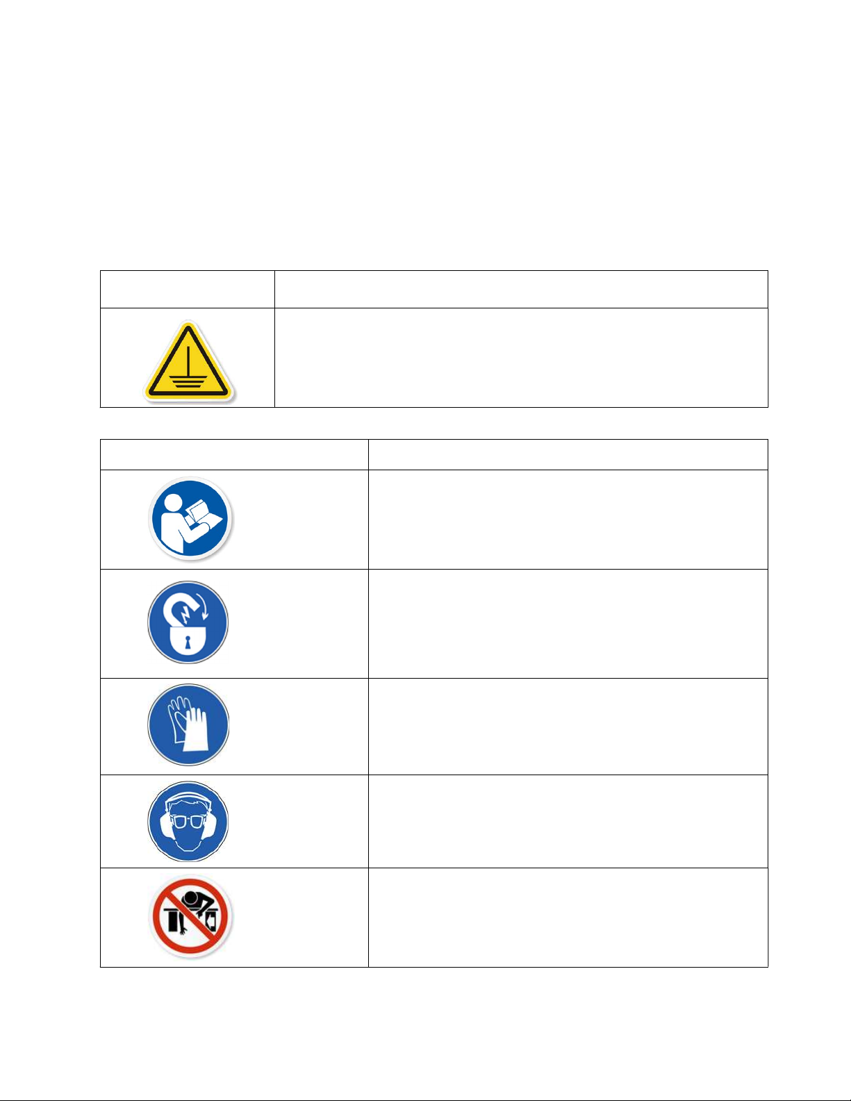
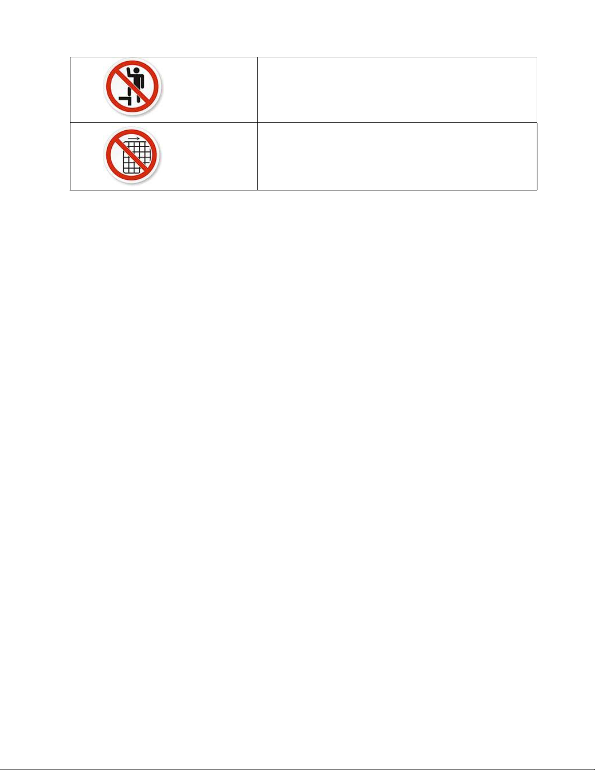
Safety Symbols Used in this Manual
The following safety alert symbols are used to alert you to potential personal injury hazards.
Obey all safety messages that follow these symbols to avoid possible injury or death.