Acson international ADB75B User manual
Ducted Blower
Split Systems
ADB-B_(i)
ADB 75-750 B
ADB 75-500 D
Models:
ADB 75/100 D
ADB 125/150 D
ADB 600 B4

TABLE OF CONTENTS
1. NOMENCLATURE ..................................................................................................... 1
- PRODUCT LINE UP ........................................................................................ 3
2. FEATURES ................................................................................................................ 9
3. APPLICATION INFORMATION
- OPERATING RANGE ..................................................................................... 10
- REFRIGERANT CIRCUIT DIAGRAM ............................................................ 11
- CONTROLLER ............................................................................................... 13
- INSTALLATION .............................................................................................. 17
4. SOUND DATA ........................................................................................................... 27
- NC CURVES .................................................................................................. 29
5. SELECTION PROCESS
- FAN PERFORMANCE CHART ...................................................................... 44
6. ENGINEERING AND PHYSICAL DATA
- GENERAL DATA ............................................................................................ 70
- COMPONENTS DATA................................................................................... 100
- SAFETY DEVICES ........................................................................................ 142
7. PERFORMANCE DATA ........................................................................................... 152
- PERFORMANCE TABLES ............................................................................ 158
8. OUTLINE AND DIMENSION .................................................................................... 181
9. ELECTRICAL DATA ................................................................................................. 199
10. WIRING DIAGRAMS.............................................................................................. 216
11. SERVICING AND MAINTENANCE ........................................................................ 238
12. TROUBLESHOOTING ........................................................................................... 240
13. EXPLODED VIEW AND PART LIST ...................................................................... 245
THIS MANUAL SUPERCEDES ADB-2009

1
1. NOMENCLATURE
ADB 200 BR
Brand
A : ACSON
Capacity
200 : 200,000 Btu/h
Series
B : B series
D : D series
Model Type
R : Heatpump
Omitted if Cooling Only
A A
AB
-
Refrigerant
Blank : R22
4 : R407C
Model Name
DB : Ducted Blower
DSB : Double Skin Ducted Blower
Electrical
A : 50Hz/1Ph/220 ~ 240V
F : 50Hz/3Ph/380 ~ 415V
Others
AA : Revision
Type of Connection
B : For Brazed
F : For Flare
Indoor

2
AMC 75 BR
Brand
A : ACSON
Capacity
75 : 75,000 Btu/h
Series
B : B series
D : D series
Model Type
R : Heatpump
Omitted if Cooling Only
A A
AB
-
Refrigerant
Blank : R22
4 : R407C
Model Name
MC : Modular Condensing Unit
LC : Single Split Condensing Unit
Electrical
A : 50Hz/1Ph/220 ~ 240V
F : 50Hz/3Ph/380 ~ 415V
Others
AA : Revision
Type of Connection
B : For Brazed
F : For Flare
Outdoor

3
W/out Control
With Contactor
W/out Contactor
L208A
U1_SB125
Sequential
SLM3
Sequential Controller
CE Mark
Without Marking
TXV
Capillary Tube
Without Expansion Device
With air filter
W/out Air Filter
Horizontal & Changeable
Horizontal & Not Changeable
Vertical & Not changeable
Vertical & Changeable
Rivet "Made In Malaysia"
Very High Static
75B ABAF X X X X X X
100B ABAH X X X X X X
125B FBAH X X X X X X X
150B FBAG X X X X X X X
FBAH X X X X X
FBAI X X X X X X X
FBAG X X X X X
FBAI X X X X X X X
FBAC X X X X X
FBAE X X X X X X X
FBAC X X X X X
FBAE X X X X X X X
FBAG W X X X X
FBAI X X X X X X X
FBAC X X X X X
FBAE X X X X X X X
FBAC X X X X X
FBAE X X X X X X X
FBAG X X X X X
FBAI X X X X X X X
FBAC X X X X X
FBAD X X X X X X X
750B5 FBAC X X X X X
Classification
300B2
350B3
300B3
Marking Air Discharge
200B2
250B2
Others
A. Filter
COOLING MODEL
Control
400B4
450B3
Nomenclature
Refrigerant
Control
Handset
500B4
600B4
ADB
Product Line Up

4
W/out Control
With Contactor
W/out Contactor
L208A
U1_SB125
Sequential Controller
SLM3
Sequential Controller
CE Mark
Without Marking
TXV
Cap. Tube & Check Valve
Withour Expansion Device
With air filter
W/out Air Filter
Horizontal & Changeable
Horizontal & Not Changeable
Vertical & Not changeable
Vertical & Changeable
Rivet "Made In Malaysia"
Very High Static
ABAE XXXXXX
ABAG X X X X X X X
ABAE XXXXXX
ABAG X X X X X X X
FBAE X X X X X X X
FBAF X X X X X X X X
FBHB X X X X X X X X
FBAA X X X X X X X
FBHA X X X X X X X X
FBAE X X X X X X X
FBHB X X X X X X X X
FBAC X X X X X X X
FBHA X X X X X X X X
200D2 FBAF X X X X X X X
250D2 FBAF X X X X X X X
300D2 FBAF X X X X X X X
400D4 FBAF X X X X X X
500D4 FBAF X X X X X X
Classification
Nomenclature
Controller Handset Marking Refrigerant
Control Filter Air Discharge Others
COOLING MODEL
75D
100D
125D
125D2
150D1
150D2
ADB
5
AMC
With Togami Contactor
With Chint Contactor
Without Contactor
With HP/LP
CE Mark
ETL
Without Marking
Scroll-Copeland
Scroll Maneurop
Reciprocating-Maneurop
Reciprocating Bristol
Reciproacating-Copeland
TXV
Capillary Tube
Bi-Flow TXV
Without Expansion Device
Centrifugal Fan
Rivet "Made In Malaysia"
With Accumulator
Phase Sequencer
Gold Fin (NA549)
FBAOXXXX X X
FBASXXXX X X
FBAMXXXX X X
FBASXXXX X X
FBAPXXXX X X
FBARXXXX XX
FBASXXXX XX
FBAHXXXX X X
FBAIXXXX XX
FBAJXXXX XX
FBARXXXX X X
FBAWXXXX XX
FBATXXXX XX
FBAYXXXX XX
FBAKXXXX X X
FBAMXXXX XX
FBAPXXXX XX
COOLING MODEL
Classification
OthersMarking
Nomenclature
XVCompressorControl
75B
150C
75C
100B
100C
125B
6
AMC
With Contactor
Without Contactor
With 24Vac Control Circuit
With HP/LP
CE Mark
ETL
Without Marking
Scroll-Copeland
Scroll Maneurop
Reciprocating-Maneurop
Reciprocating Bristol
Reciproacating-Copeland
TXV
Capillary Tube
Without Expansion Device
Centrifugal Fan
Rivet "Made In Malaysia"
With Accumulator
With Type Brazed Ball Valve
Phase Protector
Gold Fin (NA549)
FBAFXXXX X X
FBAGXXXX XX
FBAHXXXX XX
FCAAXXXX X X
FCABXXXX XXX
FBAFXXXX X X
FBAGXXXX XX
FBAHXXXX XX
FCAAXXXX X X
FCABXXXX XXX
FBAFXXXX X X
FBAGXXXX XX
FBAHXXXX XX
FCAAXXXX X X
FCABXXXX XXX
FBAGXXXX X X
FBAH X X X X X X X
FBAIXXX X XXX
FCAAXXXX X XX
FCABXXXX XXX
FCACXXX X XXXX
200D2 FBAA X X X X X X
250D2 FBAA X X X X X X
300D2 FBAA X X X X X X
Expansion
Device
Compressor OthersControl
COOLING MODEL
75D
100D
125D
150D
Nomenclature
Classification
Marking
7
A4MC
With Contactor
W/out Contactor with Auto HP/LP
W/out Contactor With Manual HP/LP
With HP/LP
Local (w/out DOL)
CE Mark
ETL
Without Marking
Scroll-Copeland
Scroll Maneurop
Reciprocating-Maneurop
Reciprocating Bristol
Reciproacating-Copeland
TXV
Capillary Tube
Without Expansion Device
Centrifugal Fan
For Sequential Controller
With Accumulator
With Type Brazed Ball Valve
Gold Fin (NA549)
FBAAXXXX XX
FBACXXXX XXX
FCAAXXXX XXX
FCABXXXX XXXXX
FBAAXXXX XX
FBACXXXX XXX
FCAAXXXX XXX
FCABXXXX XXXXX
FBAAXXXX XX
FBACXXXX XXX
FCAAXXXX XXX
FCABXXXX XXXXX
FBAAXXXX XX
FBACXXXX XXX
FCAAXXXX XXX
FCABXXXX XXXXX
Classification
Nomenclature
Control Marking Compressor Expansion
Device Others
COOLING MODEL
75D
125D
100D
150D

8
With Contactor
Without Contactor
With Auto HP/LP
With Manual HP/LP
CE Mark
ETL
Without Marking
Scroll-Daikin
Scroll-Copeland
Scroll Maneurop
Reciprocating-Maneurop
Reciprocating Bristol
Reciproacating-Copeland
TXV
Capillary Tube
Without Expansion Device
Centrifugal Fan
Phase Sequencer c/w Disc Ther
Gold Fin (NA549)
Rivet "Made In Malaysia"
With Brazed Type Ball Valve
Check valve
With Accumulator
FBCA X X X X X X X
FBEAXXX X XXX
FBCA X X X X X X X
FBEAXXX X XXX
FBCA X X X X X X X
FBEAXXX X XXX
COOLING
MODEL
75F
100F
125F
Classification
AMC
Nomenclature
Controller Marking Compressor XV Others
9
2. FEATURES
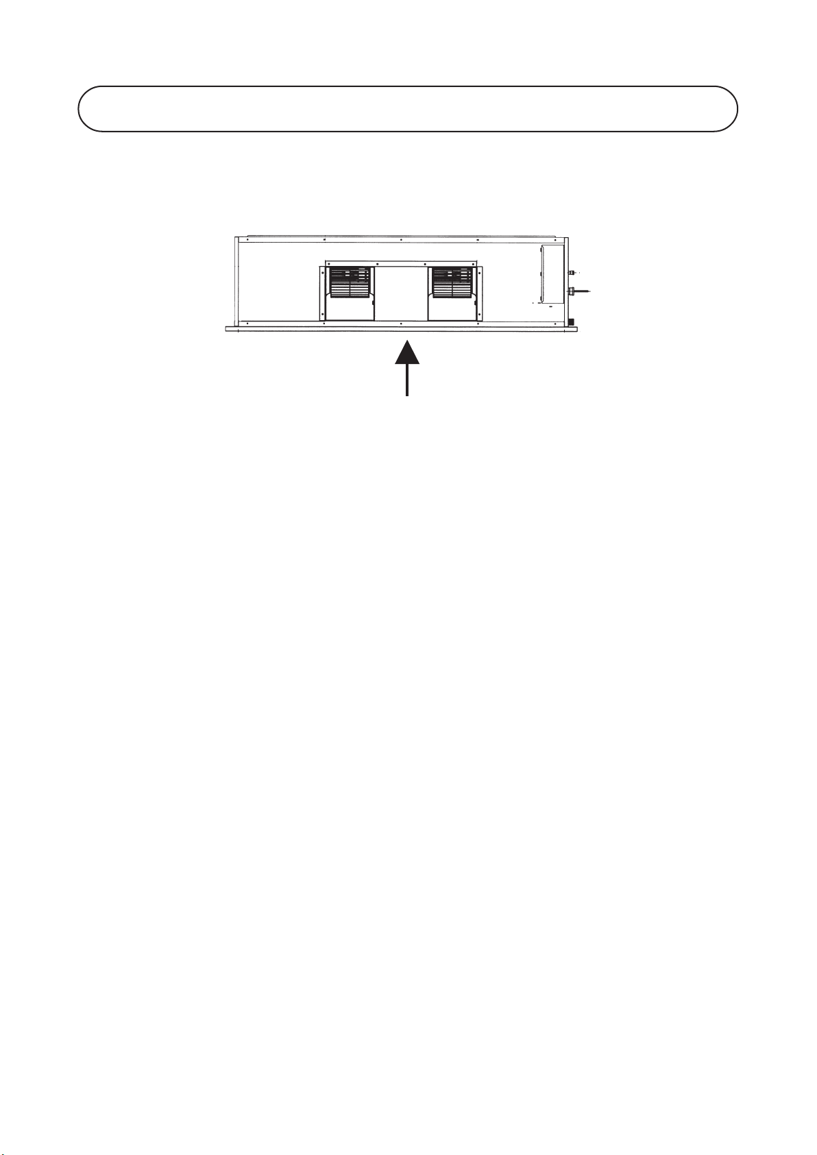
EASY MAINTENANCE
The simple design concept has provided the ease of maintenance and servicing. Access to the internal
part of the unit can be from the service panel or other side of the unit by loosening a few screws.
Only for model ADB75/100D with additional service panel from bottom
AIR DISCHARGE ORIENTATION
ADB200B and ADB75-150D models come with standard horizontal air discharge.
ADB250-500B and ADB200-500D models only come with standard vertical air discharge and they can be
converted to horizontal air discharge at the site. ADB250-500B and ADB200-500D models with horizontal air
discharge are not offered from factory. ADB600-750B models are offered in vertical and horizontal air discharge
as standard by differentiate of nomenclature.
COMPACT INDOOR UNIT
Indoor models are designed with compact size with twin coil structure. This design is able to provide some
saving in space for installation.
VERSATILITY
Multiple rooms can be cooled together at the same time by using just one unit of fan coil unit.
FRESH AIR INTAKE FOR HEALTHY LIVING
Fresh air can be introduced into the building through the design of fresh air intakes. This will help to improve the
indoor air quality.
SUPERIOR AIR DISTRIBUTION FOR COMFORTABLE LIVING
The conditioned air can be effectively distributed to every corner of the room through the ducting and this
ensure a more pleasant environment for comfort living.
FLEXIBILITY OF AIR SUPPLY
ADB200-750B and ADB125-500D models using belt driven blower such as that the air volume and static
required can be adjusted according to the requirement. This flexibility allows for wider application.
SCROLL COMPRESSOR
All outdoor units are using Scroll compressor which has better energy efficiency and quiet in operation.
SEQUENTIAL CONTROLLER AS STANDARD
This controller is supplied as the standard specification for cooling model where the systems are matching with
two outdoor units and more. The benefit of this controller is capable of part-loading of the system capacity.
10
3. APPLICATION INFORMATION
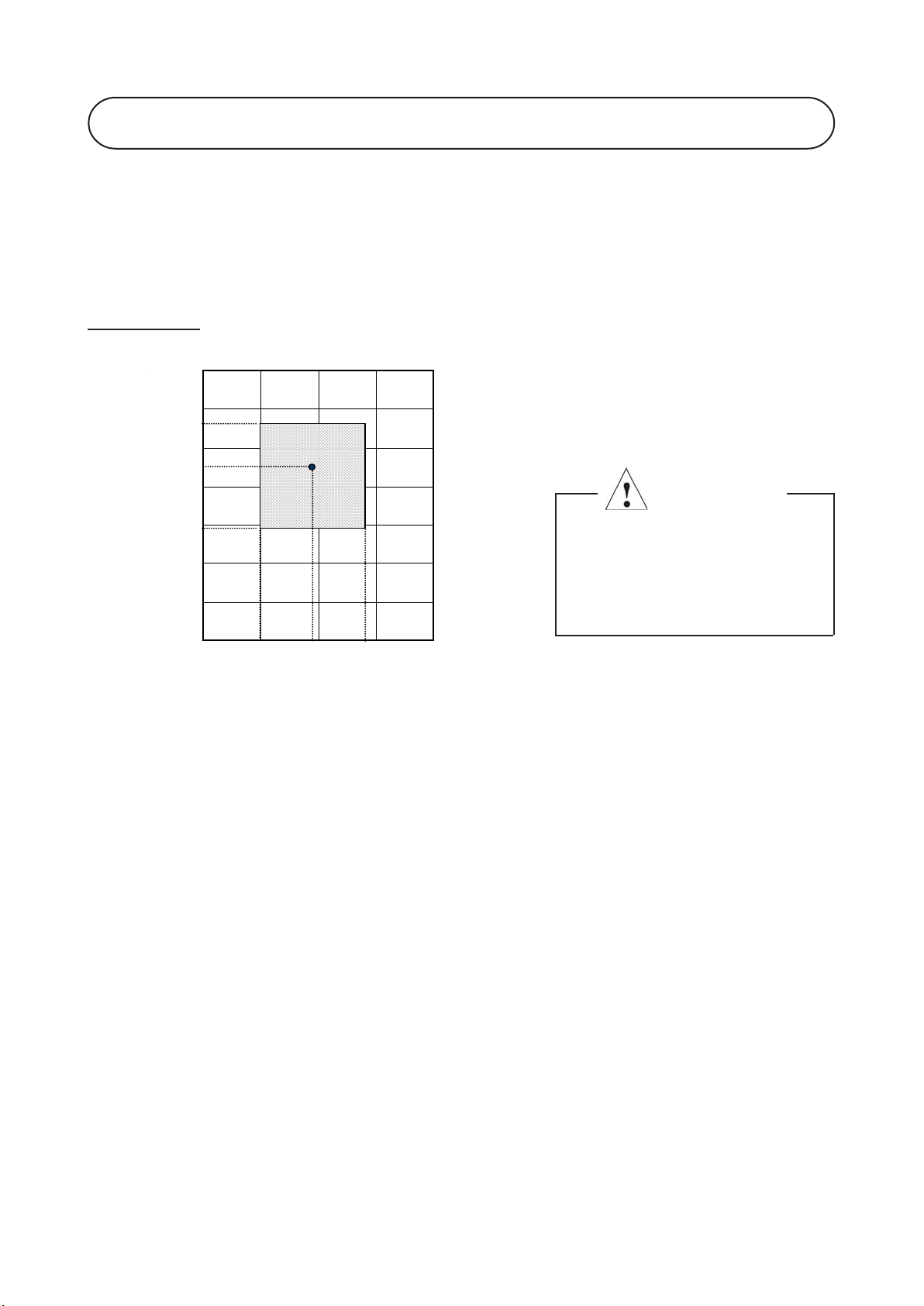
Operating Range
Ensure the operating temperature is in allowable range.
Cooling only
Caution :
The use of your air conditioner
outside the range of working
temperature and humidity can
result in serious failure.
Outdoor temp. (°CDB)
Indoor temp. (°CWB)
19
35
15
46
24
STD
11
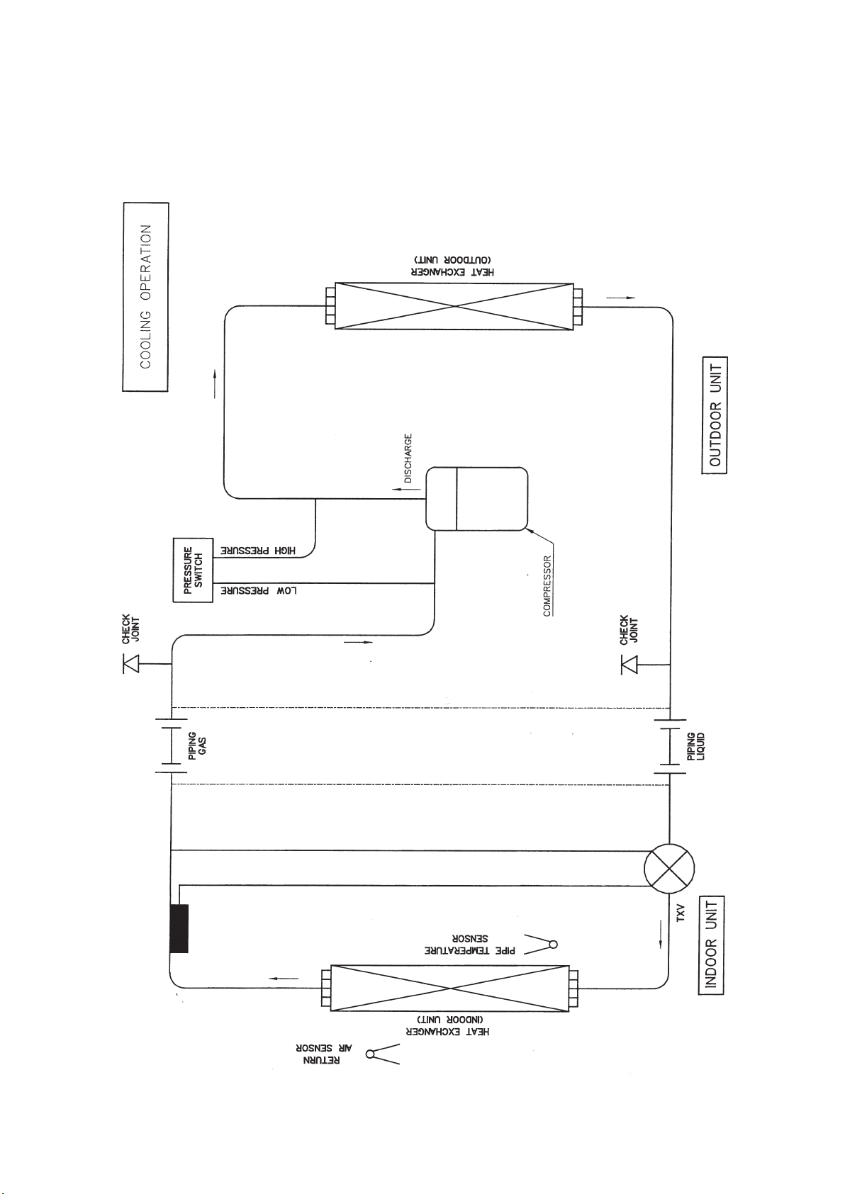
Standard Models
Refrigerant Circuit Diagram
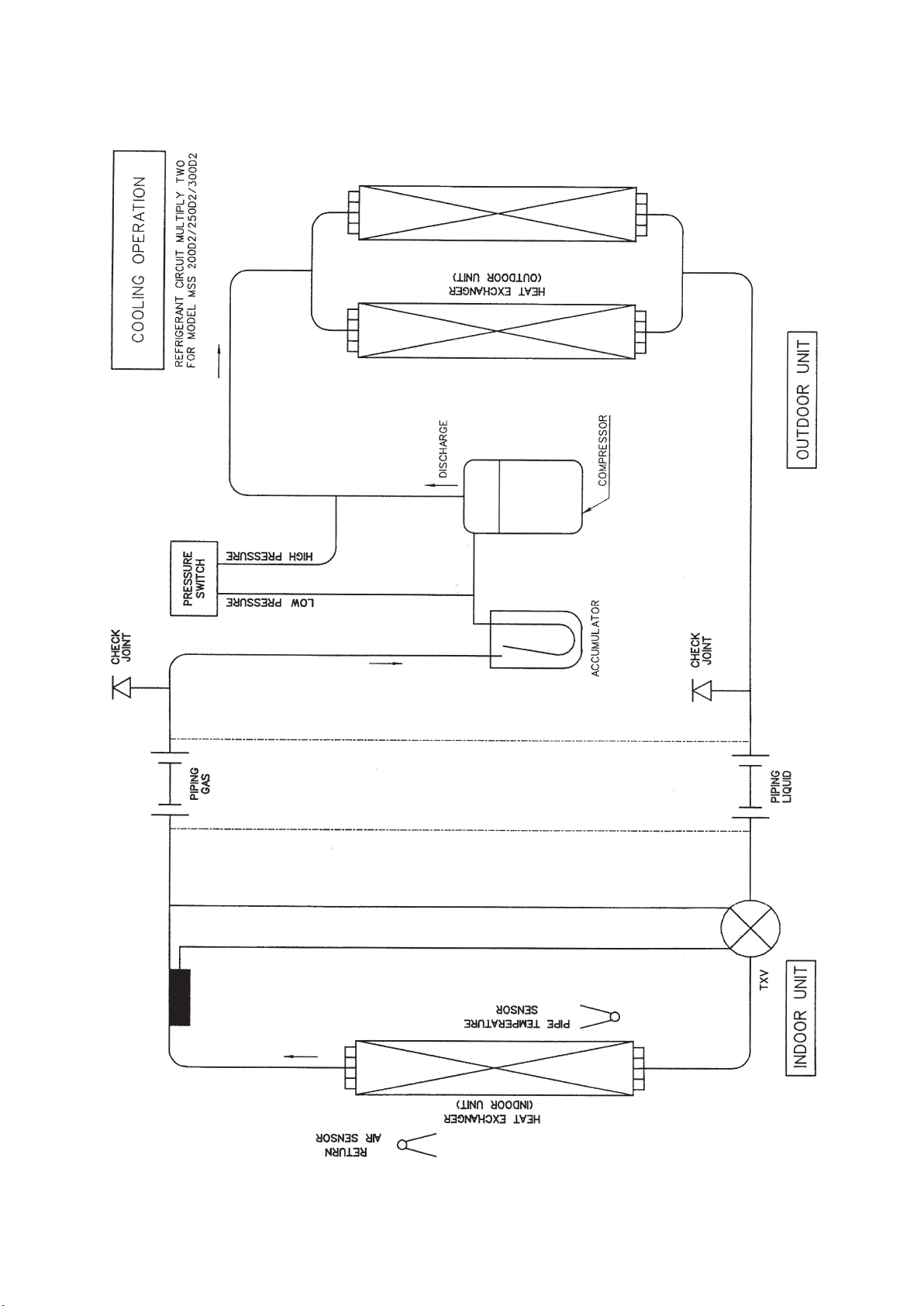
12
MODEL : AMC200D2 / 250D2 / 300D2 (WITH ACCUMULATOR)
13
ELECTRICAL CONNECTION
Wiring regulations about wire diameter differs from country to country. Please refer to your LOCAL
ELECTRICAL CODES for field wiring rules. Be sure that installation comply with such rules and regulations.
GENERAL PRECAUTION
Ensure that the rated voltage of the unit correspond to the name plate before carrying out proper wiring
according to the wiring diagram.
Provide a power outlet to be used exclusively for each unit. A power supply disconnect and a circuit breaker
for over current protection should be provided in the exclusive line.
The unit must be GROUNDED to prevent possible hazard due to insulation failures
Every wiring must be firmly connected.
Every wiring should not touch the refrigerant piping, compressor and any moving parts of fan motor.
OPERATIONAL CHECK
After all wiring is completed and the system is charged with refrigerant, make sure the unit is operating
properly. Check that :
Condenser fans are running with warm air blowing off the condensing unit.
Evaporator blowers are running and discharging cool air from ducts.
Suction line and liquid line pressures are in the region of 75 psig and 275 psig respectively.
SEQUENTIAL CONTROLLER LCD OPERATING INSTRUCTIONS
(Standard for cooling and heatpump units)
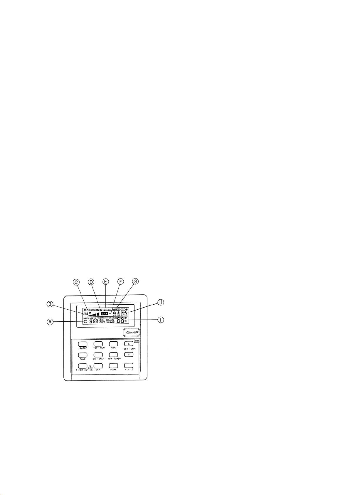
Sequential controller LCD display
A : Time display
B : Error indication
C : Compressor running display (up to 4
compressors)
D : Key lock display
E : Heater display (up to 2 heaters)
F : Energy saving mode display
G : Compressor defrost cycle display (up to 4
compressors)
H : Operation mode display
I : Temperature set display
2. OPERATING GUIDE
2.1 ON/OFF key
Press once to start the air conditioning unit.
Press again to stop the unit.
The operation lamp next to the key lights up and goes off respectively when the unit is running
or not running.
Caution : In the case when the ON/OFF key is pressed immediately after the operation is
stopped, the unit will not restart until 3 minutes later to protect the compressor.
Controllers
14
2.2 Selecting Operation Mode
Press the MODE key to select the type of operating mode. Consecutive press of the key switches the
operation over “COOL”, “HEAT”, “AUTO” and “FAN”
2.3 SAVE Mode
Press the SAVE key to select the energy saving function. This option is only available for “COOL”,
“HEAT” and “AUTO” modes.
2.4 Auxiliary Electric Heater
If the “HEAT” mode provides insufficient heating to a room even at the highest temperature setting
(30°C), press the HEATER key to activate the auxiliary electric heater. For models with two heaters,
consecutive press of the key allows the selection of one or both heaters active.
2.5 Temperature Setting
To set the desired room temperature, press or to increase or decrease the set
temperature in the range of 16°C to 30°C.
Press both and simultaneously to toggle between °C and °F setting.
2.6 Time Setting
Real time Clock
Press the CLOCK key once to activate set clock mode.
Press again to disable set clock mode.
Under set clock mode, the time of the present day can be set by pressing the respective MINUTE, HOUR
and DAY key.
7 days timer
Press the ON TIMER key to activate auto ON timer mode. Under this mode, press the respective MINUTE,
HOUR and DAY key to select the time of the week when the air-conditioning unit is to automatically start
running. Press the ON TIMER key again to save the setting.
Press the OFF TIMER key to activate auto OFF timer mode. Under this mode, press the respective
MINUTE, HOUR and DAY key to select the time of the week when the air-conditioning unit is to automatically
stop running. Press the ON TIMER key again to save the setting.
Then to activate the 7 days timer, press and hold the TIMER ACTIVE key until the word “TIMER ACTIVE”
appears on the LCD screen. Repeat the same step to disable the 7 days timer.
2.7 Other Function
Key Lock
Press the MINUTE key 3 times consecutively to activate the key lock. A “KEY LOCK” symbol will appear
on the LCD screen. At this point, only the ON/OFF key is valid.
To disable the key lock, again press the MINUTE key 3 times consecutively.
Test run
Press the TEST key 2 times consecutively to test run the unit.
15
3. ERROR CODE
When the system is on and an error occurs, the ON/OFF LED on the LCD panel will blink and an error
code is shown. When the system is off and there is a thermistor error, the ON/OFF LED is off but the
error code is still displayed. Each error code represents different message as below
Error code Possible fault Error code Possible fault
E01 Require manual reset (possible causes) E19 Indoor coil sensor 4 short
E02 Compressor 1 high temperature (overload) E20 Indoor coil sensor 1 open
E03 Compressor 2 high temperature(overload) E21 Indoor coil sensor 2 open
E04 Compressor 3 high temperature(overload) E22 Indoor coil sensor 3 open
E05 Compressor 4 high temperature(overload) E23 Indoor coil sensor 4 open
E06 Compressor 1 high pressure trip / contact open E24 Outdoor coil sensor 1 short
E07 Compressor 2 high pressure trip / contact open E25 Outdoor coil sensor 2 short
E08 Compressor 3 high pressure trip / contact open E26 Outdoor coil sensor 3 short
E09 Compressor 4 high pressure trip / contact open E27 Outdoor coil sensor 4 short
E10 Compressor 1 trip / low R-22 / outdoor abnormal E28 Outdoor coil sensor 1 open
E11 Compressor 2 trip / low R-22 / outdoor abnormal E29 Outdoor coil sensor 2 open
E12 Compressor 3 trip / low R-22 / outdoor abnormal E30 Outdoor coil sensor 3 open
E13 Compressor 4 trip / low R-22 / outdoor abnormal E31 Outdoor coil sensor 4 open
E14 Room sensor short E32 Compressor 1 de-ice
E15 Room sensor open E33 Compressor 2 de-ice
E16 Indoor coil sensor 1 short E34 Compressor 3 de-ice
E17 Indoor coil sensor 2 short E35 Compressor 4 de-ice
E18 Indoor coil sensor 3 short
4. INSTALLATION OF LCD REMOTE CONTROLLER
4.1 Accessories
The following accessories are included. If any part is missing, contact your dealer immediately.
1Remote controller
2Wooden screw 4.1 x 16 (2 pieces)
3Instruction manual
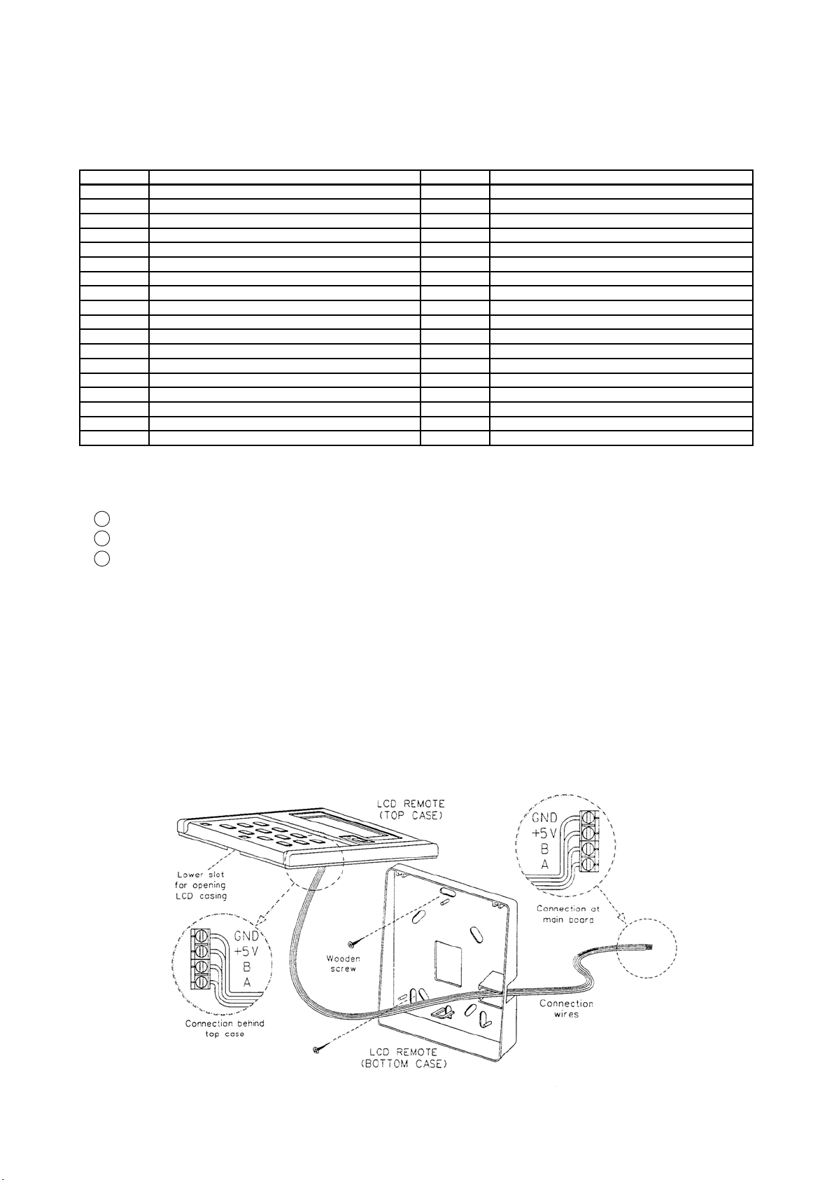
4.2 Step by step guide
i) First, open up the casing of the LCD remote controller into its top and bottom case using a
screwdriver. To do this, insert the screwdriver into the lower slot and slide it in the outward direction.
ii) Fix the bottom case onto the wall with the 2 wooden screws provided. Then, insert the 4 connecting
wires (from the main board) through the slot on the lower right.
iii) Connect one end in each of the 4 wires to the terminal block behind the top case as shown below.
The wire that goes into the “GND” terminal at the top case must be connected at the other end to
the “GND” terminal at the main board. The same goes for the “+5V”, “B” and “A” connection.
iv) Fasten back the top and bottom case into place. Hook the two upper claws into their respective slots
and snap the lower part shut.
16
5. AUTO RANDOM RESTART
When power resumed, the unit will automatically restart and operate at the previous setting as before power
failure occurred. (Remove jumper at JH/JP1 will cancel the auto random restart function. Please refer to
wiring diagram for the location of the JH/JP1).
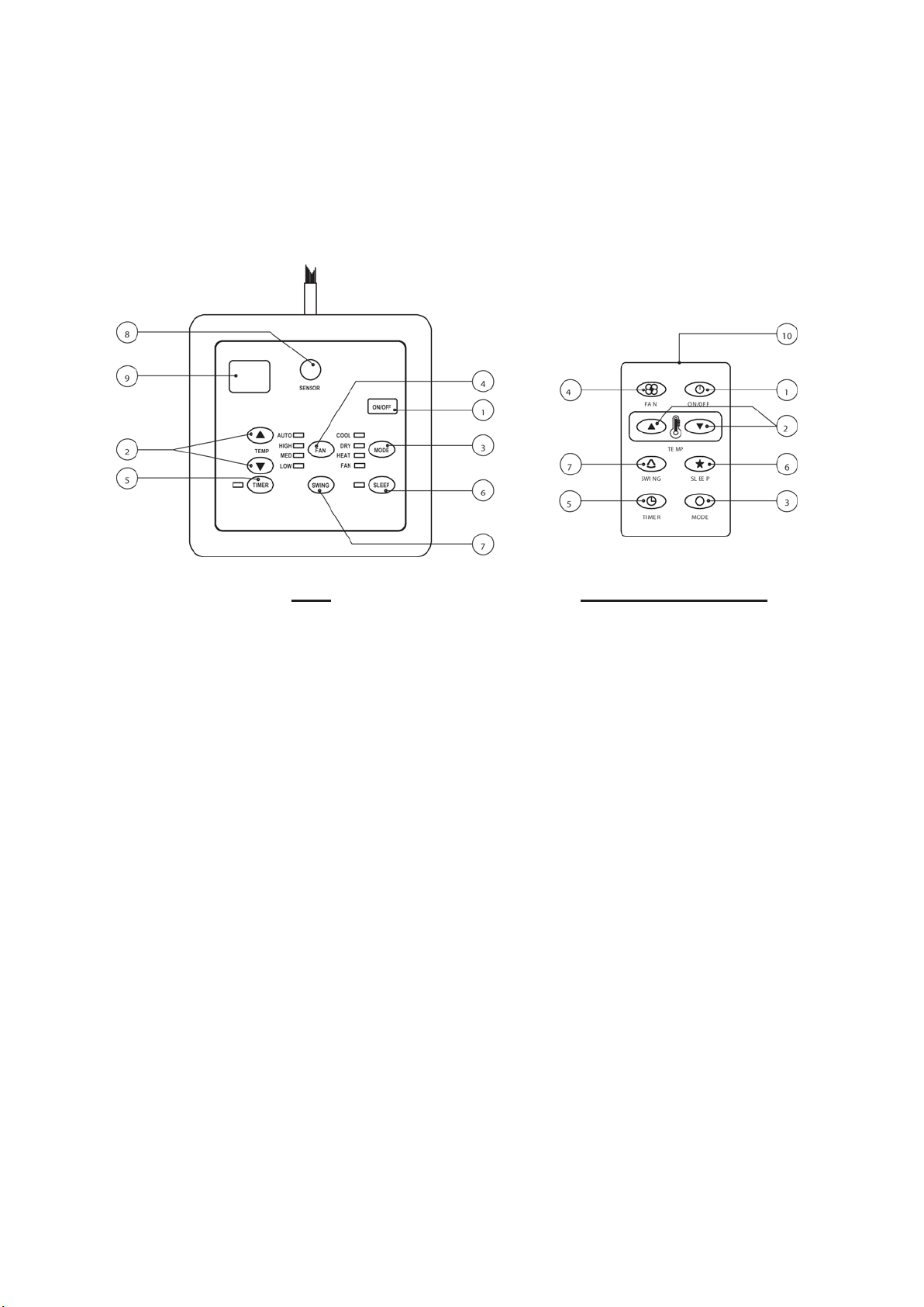
1. “ON/OFF” switch
•Press to start the air conditioner unit.
•Press again to stop the unit.
2. Temperature setting
•Set the desired room temperature.
•Press button to increase or decrease the set
temperature. Setting range are between 16°C
to 30°C (60°F to 80°F).
3. Operation Modes
•Press the “mode” button for select the type of
operating mode.
- Cooling Only :
COOL, DRY, FAN
- Heat Pump :
AUTO, COOL, DRY, HEAT, FAN
(AUTO mode is represented by bothCOOL and
HEAT LED light on)
4. Fan Speed selection
•Press the button until the desired fan speed is
achieved.
5. Timer
•Press the set button to select the switch timer
of the air conditioner unit (the setting range is
between 1 to 10 hours).
6. “Sleep” mode
•Press button to activate the sleep function can
only be activated under “cool” or heating mode
operation. When it is activated under “cool”
mode operation, the set temperature will
increase 0.5°C after 30 minutes, 1°C after 1 hour
and 2°C after 2 hours. If it is actiaved under
“HEAT” mode operation, the set temperature
will be descreased 0.5°C after 30 minutes, 1°C
after 1 hour and 2°C after 2 hours.
7. Air Swing
•Press button to activate the automatic air swing
function.
8. Sensor
•Infra red sensor to receive signals from wireless
controller.
9. LED Display
•To display the set temperature (in °C) and timer
delay setting (in hours).
10. Transmission source
•To transmit signals to the air conditioner.
SLM AC-5300 (OPTIONAL)
SLM CONTROLLER OPERATING INSTRUCTIONS

17
SPECIAL PRECAUTIONS WHEN DEALING WITH REFRIGERANT R407C UNIT
1) WHAT IS NEW REFRIGERANT R407C?
R407C is a zeotropic refrigerant mixture which has Zero Ozone Depletion Potential (ODP = 0) and thus
conformed to the Montreal Protocol regulation. It requires Polyol-ester oil (POE) oil for its compressor’s
lubricant. Its refrigerant capacity and performance are about the same as the refrigerant R22.
2) COMPONENTS
Mixture weight compositionR32(23%), R125(25%), R134a(52%)
3) CHARACTERISTIC
•R407C liquid and vapor components have different compositions when the fluid evaporates or condenses.
Hence, when leak occurs and only vapor leaks out, the composition of the refrigerant mixture left in the
system will change and subsequently affect the system performance. DO NOT add new refrigerant to
leaked system. It is recommended that the system should be evacuated thoroughly before recharging with
R407C.
•When refrigerant R407C is used, the composition will differ depending on whether it is in gaseous or liquid
phase. Hence when charging R407C, ensure that only liquid is being withdrawn from the cylinder or can.
This is to make certain that only original composition of R407C is being charged into the system.
•POE oil is used as lubricant for R407C compressor, which is different from the mineral oil used for R22
compressor. Extra precaution must be taken not to expose the R407C system too long to moist air.
4) CHECK LIST BEFORE INSTALLATION/SERVICING
•Tubing
Refrigerant R407C is more easily affected by dust of moisture compared with R22, make sure to temporarily
cover the ends of the tubing prior to installation
•Compressor oil
No additional charge of compressor oil is permitted.
•Refrigerant
No other refrigerant other that R407C
•Tools
Tools specifically for R407C only (must not be used for R22 or other refrigerant)
i) Manifold gauge and charging hose
ii) Gas leak detector
iii) Refrigerant cylinder/charging cylinder
iv) Vacuum pump c/w adapter
v) Flare tools
vi) Refrigerant recovery machine
5) HANDLING AND INSTALLATION GUIDELINES
Like R22 system, the handling and installation of R407C system are closely similar. All precautionary measures;
such as ensuring no moisture, no dirt or chips in the system, clean brazing using nitrogen, and thorough leak
check and vacuuming are equally important requirements. However, due to zeotropic nature of R407C and its
hydroscopic POE oil, additional precautions must be taken to ensure optimum and trouble free system operation.
a) Filter dryer must be installed along the liquid line for all R407C air conditioners. This is to minimise the
contamination of moisture and dirt in the refrigerant system. Filter dryer must be of molecular sieve type.
For a heat pump system, install a two--way flow filter dryer along the liquid line.
b) During installation or servicing, avoid prolong exposure of the internal part of the refrigerant system to
moist air. Residual POE oil in the piping and components can absorb moisture from the air.
Installation

18
c) Ensure that the compressor is not expose to open air for more than the recommended time specified by
its manufacturer (typically less than 10 minutes). Removed the seal plugs only when the compressor is
about to be brazed.
d) The system should be thoroughly vacuumed to 1.0 Pa ( 700mmHg) or lower. This vacuuming level is
more stringent than R22 system so as to ensure no incompressible gas and moisture in the system.
e) When charging R407C, ensure that only liquid is being withdrawn from the cylinder or can. This is to
ensure that only the original composition of R407C is being delivered into the system. The liquid composition
can be different from the vapor composition.
f) Normally, the R407C cylinder or can is being equipped with a dip pipe for liquid withdrawal. However, if
the dip pipe is not available, invert the cylinder or can so as to withdraw liquid from the valve at the
bottom.
g) When servicing leak, the top up method, commonly practiced for R22 system, is not recommended for
R407C system. Unlike R22 where the refrigerant is of a single component, the composition of R407C,
which made up of three different components, may have changed during the leak. Consequently, a top up
may not ensure that the R407C in the system is of original composition. This composition shift may
adversely affect the system performance. It is recommended that the system should be evacuated thor-
oughly before recharging with R407C.
R32/R125/R134
33% / 33% / 34%
23% / 25% / 52%
Composition of R407C in vapour phase
is different from liquid phase.
D
ip-pipe
I
nvert cylinde
r
without dip-pipe
L
iquid
withdrawal
This manual suits for next models
39
Table of contents
Popular Blower manuals by other brands


Grizzly
Grizzly ELS 2801 Prof Translation of the original instructions for use

Mazzoni
Mazzoni FLASH 650M Use and maintenance manual

MTD
MTD BV3100 Operator's manual

Craftsman
Craftsman 125B Operator's manual

Showa Denki
Showa Denki U2S Series Instruction Manual & Directions

Minuteman
Minuteman C44000-01 Operation, service and parts manual