ACTi KCM-7911 User manual

2013/12/03
Outdoor Hemispheric
Mounting on a Vertical Pole
Using the Tilted Mount
Installation Guide
For Models:
KCM-7911

www.acti.com
Installation Guide
2
Table of Contents
Mounting Solutions............................................................3
Installation Procedures using Naked Cable ....................4
Step 1: Attach the Pole Mount Kit ............................................................ 4
Step 2: Attach the Tilted Mount................................................................ 6
Step 3: Prepare for Waterproof Installation............................................. 6
Step 4: Open the Camera Cover............................................................... 8
Step 5: Connect the Cable(s).................................................................... 9
Step 6: Install the Camera to the Tilted Mount...................................... 10
Step 7: Close the Cover ...........................................................................11
Step 8: Access the Camera Live View.....................................................11
Installation Procedures using Flex Conduit..................12
Step 1: Attach the Pole Mount Kit .......................................................... 12
Step 2: Attach the Tilted Mount.............................................................. 14
Step 3: Open the Camera Cover............................................................. 14
Step 4: Prepare for Waterproof Installation........................................... 15
Step 5: Install the Camera to the Tilted Mount...................................... 19
Step 6: Close the Cover .......................................................................... 19
Step 7: Access the Camera Live View.................................................... 19
Appendices.......................................................................20
Connecting a Power Adaptor (Optional)................................................ 20
Connecting DI/DO Devices (Optional).................................................... 22
Connecting Audio In / Out Devices (Optional) ...................................... 25
Safety Information............................................................26

www.acti.com
Installation Guide
3
Mounting Solutions
The camera can be mounted on a vertical pole with the camera facing forward using the Pole
Mount with Surface Mount (SMAX-0136). With this accessory combination, the camera faces
forward with a 10 tilt.
The camera comes with two (2) glands used for waterproof installation: Cable gland and Conduit
Gland.
Cable Gland
Conduit Gland
For use with an EXTERIOR-GRADE
Ethernet cable. Exterior-grade Ethernet
cables are already waterproof.
For use with 3/8” flexible conduit.
Recommended when an exterior-grade
Ethernet cable is not available or when other
input/output devices or an external power
adaptor will be connected to the camera.
Determine the type of waterproof solution that is applicable to your installation requirements and
prepare the necessary accessories or purchase extra materials.
Installation using Naked Cable: This installation uses the supplied cable gland and an
exterior-grade Ethernet cable (not supplied).
Installation Using Flexible Conduit: This installation uses the supplied conduit gland
and a 3/8” flexible conduit (not supplied). This is the recommended solution if other
input / output devices or an external power adaptor will be connected to the camera.
and

www.acti.com
Installation Guide
4
Installation Procedures using Naked
Cable
This section provides step-by-step procedures in installing the camera on a vertical pole using
the tilted mount and how to waterproof the cabling connection using a naked Ethernet cable.
Before installation, prepare the following tools and accessories which are not included in the
camera package, thus must be purchased separately:
Pole Mount with Surface Mount (SMAX-0136)
Exterior-grade Ethernet Cable
Step 1: Attach the Pole Mount Kit
1. Using a screwdriver, turn the screw head of the wire strap counter-clockwise continuously
until the two ends are detached.
2. Insert the wire strap through the strap holes of the pole mount.

www.acti.com
Installation Guide
5
3. Do steps 1 and 2 to the other wire strap.
4. Position the pole mount with the cable path up and encircle the pole with the wire straps.
NOTE: The wire straps can hold between 134 ~ 228 mm (5.28 ~ 9 in.) pole diameter.
5. Continuously turn the screw head clockwise to adjust the wire strap until it snugly fits the pole.
Do the same to the other wire strap.
This side up
www.acti.com
Installation Guide
6
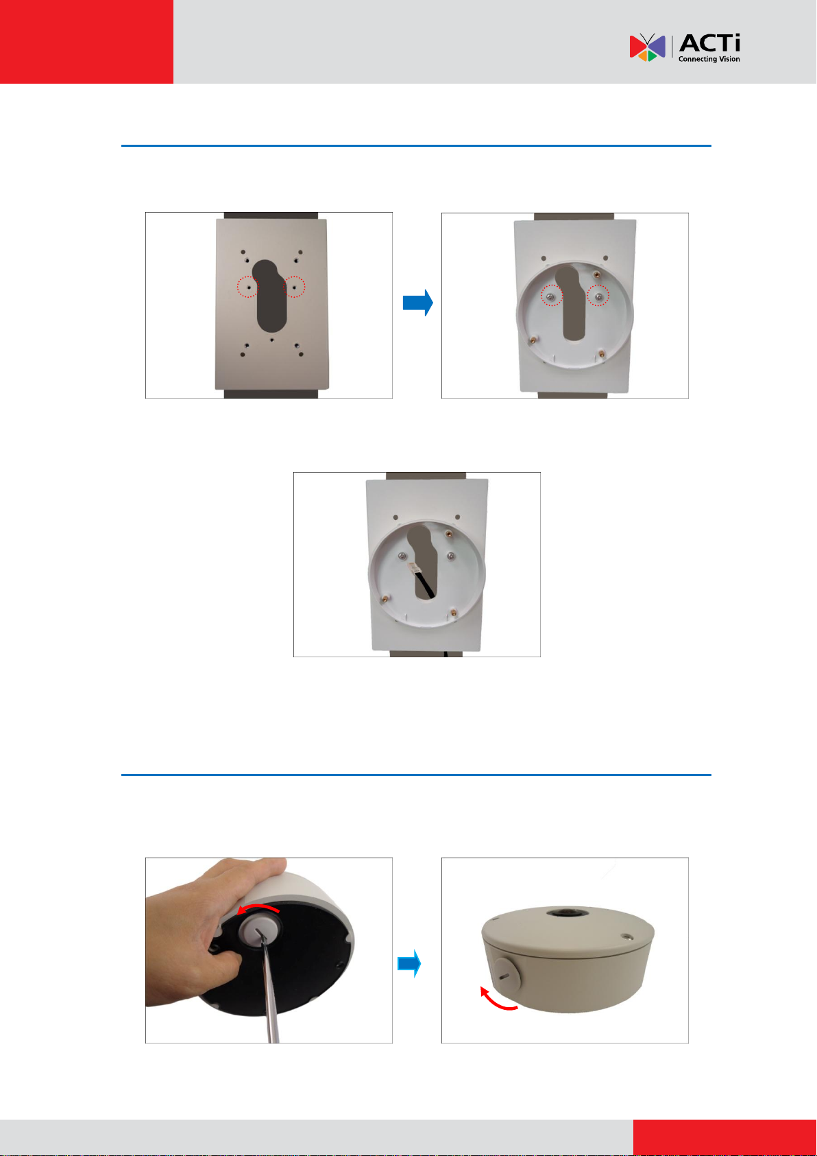
Step 2: Attach the Tilted Mount
1. Attach two (2) screws (included in the pole mount package) to secure the tilted mount to the
pole mount.
2. From the network side, route the Ethernet cable along the pole to pass through the hole on
pole mount and tilted mount.
Step 3: Prepare for Waterproof Installation
1. Remove the cap covering the bottom hole of the camera, and attach the cap to the side hole
to close it. The network cable will pass through the bottom hole.
www.acti.com
Installation Guide
7
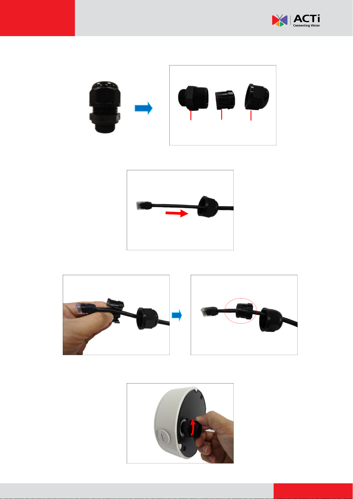
2. Disassemble the cable gland as shown below:
3. Insert the clamping nut into the Ethernet cable of the camera side.
4. Insert the sealing insert with claw.
5. Attach the cable gland body to the hole of the camera.
Body
(with Washer)
Sealing Insert
with Claw
Clamping
Nut


www.acti.com
Installation Guide
9
Step 5: Connect the Cable(s)
1. Insert the Ethernet cable through the cable gland body and connect it to the Ethernet port of
the camera.
2. Insert the sealing insert with claw into the cable gland body and then attach the clamping nut
to complete the cable solution.
NOTE: Make sure the clamping nut is tightly attached to the cable gland body.

www.acti.com
Installation Guide
10
Step 6: Install the Camera to the Tilted Mount
1. If necessary, insert a memory card into the card slot of the camera.
2. Align the camera to the tilted mount as the cable is pushed through the cable hole on the
tilted mount and pole mount.
3. Attach the camera to the tilted mount using the three (3) screws supplied in the Tilted Mount
package.
NOTE: Make sure the tilted mount screws have rubber rings. If the screws you received do
not have rubber rings, please contact your local sales agents or our Customer Help Desk
(CHD) for support.
Rubber Ring
Other manuals for KCM-7911
3
Table of contents
Other ACTi Digital Camera manuals


