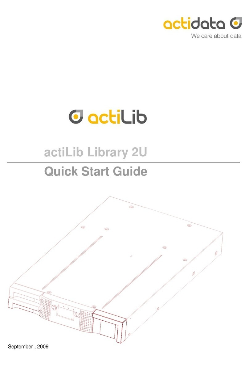
Actidata actiLib Autoloader 2U Troubleshooting guide

actiLib Autoloader 2U
User and Service Guide
Date: September 17, 2009

Copyright © 2009 actidata Storage Systems GmbH
The information contained in this document is subject to change without notice
This document contains proprietary information which is protected by copyright. All rights are
reserved. No part of this document may be reproduced, modified, distributed, or translated to another
language without the prior written consent of actidata Storage Systems GmbH.
actidata Storage Systems GmbH,
Wulfshofstrasse 16,
44149 Dortmund
www.actidata.com
This document may describe designs for which patents are pending, or have been granted. By
publishing this information, actidata conveys no license under any patents or any other rights.
actidata does not accept liability for errors contained herein or for incidental or consequential damages
(including lost profits) in connection with the furnishing, performance or use of this material whether
based on warranty, contract, or other legal theory. actidata makes no representation or warranty with
respect to the contents of this document and specifically disclaims any implied warranties of
merchantability or fitness for any particular purpose. Further, actidata reserves the right to revise or
change this document without obligation on the part of actidata to notify any person or organization of
such revision or change.
Every effort has been made to acknowledge trademarks and their owners. All trademarks within this
document are the property of their respective owners. Trademarked names are used solely for
identification or exemplary purposes, and any omissions are unintentional.
Published: September, 2013 Copyright
Revision History
Date
Issue
Revision
Description of changes
2009-21-09
Revision
1
None

Contacting actidata
Europe
APAC
actidata Storage Systems GmbH
Wulfshofstrasse 16,
44149 Dortmund
www.actidata.com
actidata Storage Systems GmbH
Singapore
www.actidata.com

About this guide
This guide provides information about:
Installing the actiLib Library 2U
Configuring and operating the actiLib Library 2U
Troubleshooting the actiLib Library 2U
Upgrading and servicing the tape library
Installing the Optional Remote Management Unit (RMU)
Installing the tape library in a Rack
Intended audience
This guide is intended for system administrators and general users who need physical and functional
knowledge of the actiLib Library 2U

1 Warnings and symbols
!
!
IMPORTANT
All safety and operating instructions should be read before this product is
operated, and should be retained for future reference. This unit has been
engineered and manufactured to assure your personal safety. Improper use
can result in potential electrical shock or fire hazards. In order not to defeat
the safeguards, observe the following basic rules for its installation, use and
servicing.
DANGER
High voltage!
Risk of electric shock.
Do not remove cover (or back). No user-serviceable parts inside.
Refer servicing to qualified service personnel.
DANGER
A danger condition due to the weight of the unit. Weight symbols
are accompanied by an approximation of the product’s weight.
CAUTION
A discharge of static electricity can damage static-sensitive devices
or micro circuitry. Proper packaging and grounding techniques are
necessary precautions to prevent damage.
NOTE
Provides additional information.
Ventilation –The product should be situated so that its location or position does not interfere with
proper ventilation.
Heat –The product should be situated away from heat sources such as radiators, heat registers,
furnaces, or other heat producing appliances.
Power sources –The product should be connected to a power source only of the type directed in
the operating instructions or as marked on the product.
Power cord protection –The AC line cord should be routed so that it is not likely to be walked on
or pinched by items placed upon or against it, paying particular attention to the cord at the wall
receptacle, and the point where the cord exits from the product.
Object and liquid entry –Care should be taken to insure that objects do not fall and liquids are not
spilled into the product’s enclosure through openings.

Servicing –The user should not attempt to service the product beyond that described in the
operating instructions. All other servicing should be referred to qualified service personnel.
1.1 Precautions
Do not expose the unit to moisture. The operating temperature for this unit is between 10°C (50°F)
and 35°C (95°F).
Use the unit on a firm level surface free from vibration.
Do not place anything on top of the unit.
1.2 Product Warranty Caution
The warranty for the tape library shall not apply to failures of any unit when:
The tape library is repaired or modified by anyone other than the manufacturer's personnel or
approved agent.
The tape library is physically abused or used in a manner that is inconsistent with the operating
instructions or product specification defined by the manufacturer.
The tape library fails because of accident, misuse, abuse, neglect, mishandling, misapplication,
alteration, faulty installation, modification, or service by anyone other than the factory service
center or its approved agent.
The tape library is repaired by anyone, including an approved agent, in a manner that is contrary
to the maintenance or installation instructions supplied by the manufacturer.
The manufacturer's serial number tag is removed.
The tape library is damaged because of improper packaging on return.
Unauthorized modifications to the unit configuration by the customer may result in loss of
guarantee by the vendor.
1.3 Rack stability
WARNING
To reduce the risk of personal injury or damage to equipment:
Extend levelling jacks to the floor.
Ensure that the full weight of the rack rests on the levelling jacks.
Install stabilizing feet on the rack.
In multiple-rack installations, secure racks together.
Extend only one rack component at a time. Racks may become unstable
if more than one component is extended.

2 Contents
1Warnings and symbols................................................................................................................5
1.1 Precautions..........................................................................................................................6
1.2 Product Warranty Caution ...................................................................................................6
1.3 Rack stability........................................................................................................................6
2Contents........................................................................................................................................7
3Tables..........................................................................................................................................11
4Installing the tape library ..........................................................................................................12
4.1 actiLib Library 2U features and requirements....................................................................12
4.2 SCSI requirements ............................................................................................................12
4.3 SCSI host bus adapters (HBAs)........................................................................................12
4.4 LUN scanning ....................................................................................................................13
4.4.1 Preparing the host...................................................................................................13
4.4.2 Verifying the connection..........................................................................................13
4.5 actiLib Library 2U overview................................................................................................14
4.5.1 Front panel overview...............................................................................................14
4.5.2 Operator control panel buttons................................................................................15
4.5.3 Back panel overview................................................................................................16
4.6 Installing the library............................................................................................................18
4.6.1 Choosing a location.................................................................................................18
4.6.2 Unpacking the tape library.......................................................................................19
4.6.3 Identifying product components ..............................................................................19
4.6.4 Removing the shipping lock ....................................................................................20
4.6.5 Rackmounting the library.........................................................................................22
4.6.6 Connecting the SCSI and power cable ...................................................................24
5Operating the tape library .........................................................................................................27
5.1 Operating Modes ...............................................................................................................27
5.2 OCP Philosophy ................................................................................................................27
5.3 Power-Up Display..............................................................................................................28
5.4 Note about the LED’s.........................................................................................................29
5.5 Input Modes.......................................................................................................................29
5.5.1 Selectable predefined values ..................................................................................29
5.5.2 Toggle values..........................................................................................................29
5.5.3 Numerical values.....................................................................................................30
5.6 Power ON/OFF..................................................................................................................30
5.7 OCP Menu Flow Charts.....................................................................................................31
5.8 Partitioning the Library.......................................................................................................38
5.8.1 Drive naming ...........................................................................................................38
5.8.2 Mixing of drives........................................................................................................38
5.9 Tape cartridges..................................................................................................................39
5.9.1 actiLib Library 2U tridge type...................................................................................39
5.9.2 Using and maintaining tape cartridges....................................................................39
5.9.3 Labeling tape cartridges..........................................................................................40
5.9.4 Write-protecting tape cartridges ..............................................................................41
5.9.5 Backward read compatibility....................................................................................41
5.9.6 Barcode reader........................................................................................................41
5.9.7 Magazines ...............................................................................................................41
5.9.8 Inserting tape cartridges into a magazine ...............................................................42
5.9.9 Mail slot ...................................................................................................................42
6Remote management unit (RMU) .............................................................................................44

6.1 Overview............................................................................................................................44
6.2 Operations available through the RMU .............................................................................44
6.3 Library status icons............................................................................................................45
6.4 Login..................................................................................................................................45
6.5 Identity ...............................................................................................................................46
6.5.1 Viewing static library information.............................................................................46
6.5.2 Viewing static drive information...............................................................................46
6.6 Status.................................................................................................................................47
6.6.1 Viewing dynamic library information........................................................................47
6.6.2 Viewing dynamic drive information..........................................................................47
6.6.3 Viewing the tape cartridge inventory.......................................................................48
6.7 Configuration .....................................................................................................................48
6.7.1 Changing the system configuration.........................................................................48
6.7.2 Changing the logical libraries ..................................................................................49
6.7.3 Changing the license key ........................................................................................49
6.7.4 Changing the drive configuration.............................................................................50
6.7.5 Changing the network configuration........................................................................50
6.7.6 Changing the user names and password................................................................51
6.7.7 Setting date/time......................................................................................................51
6.7.8 Setting error log mode.............................................................................................52
6.7.9 Setting event notification parameters......................................................................52
6.7.10Restoring factory defaults........................................................................................53
6.8 Operations .........................................................................................................................53
6.8.1 Moving media within the library...............................................................................53
6.8.2 Determining current media inventory ......................................................................54
6.8.3 Releasing and replacing magazines .......................................................................54
6.9 Service...............................................................................................................................55
6.9.1 Performing general library diagnostics....................................................................55
6.9.2 Determining and updating firmware ........................................................................55
6.9.3 Rebooting the library ...............................................................................................56
6.9.4 Viewing library logs..................................................................................................56
6.9.5 Cleaning tape drive(s) .............................................................................................57
7Servicing the tape library..........................................................................................................58
7.1 Possible tools needed........................................................................................................58
7.2 Electrostatic Discharge......................................................................................................58
7.3 Removing and replacing a tape drive................................................................................59
7.4 Removing and replacing a power supply...........................................................................61
7.5 Removing and replacing the library controller ...................................................................62
7.6 Removing and replacing the base chassis........................................................................63
8Troubleshooting.........................................................................................................................65
8.1 Installation problems..........................................................................................................65
8.2 Troubleshooting table........................................................................................................66
8.3 Service Procedures ...........................................................................................................70
8.3.1 Removing stuck tapes from slots ............................................................................70
8.3.2 Removing and replacing a magazine using the OCP .............................................71
8.3.3 Using the remote management unit........................................................................72
8.3.4 Magazine emergency release.................................................................................73
8.4 Tape library error codes.....................................................................................................74
9Technical specifications ...........................................................................................................80
9.1 Physical actiLib Library 2U specifications..........................................................................80
9.2 Tape library operation specifications.................................................................................80
9.3 Environmental specifications.............................................................................................81
10 Regulatory Information .............................................................................................................82
11 Index............................................................................................................................................84

Figures
Figure 1 Front panel overview...............................................................................................................14
Figure 2 LED’s.......................................................................................................................................15
Figure 4 Back panel overview with one half height LTO SCSI, SAS, FC tape drive ............................16
Figure 5 Back panel overview with two half height LTO SCSI, SAS, FC tape drives...........................16
Figure 7 Shipping lock and label ...........................................................................................................20
Figure 8 Shipping lock and label on the rear panel...............................................................................20
Figure 9 Shipping lock before transportation ........................................................................................21
Figure 10 Installing the rails into the rack..............................................................................................22
Figure 11 Installing the mounting brackets and guide pulleys ..............................................................23
Figure 12 Securing the library to the rack .............................................................................................24
Figure 13 Attaching the SCSI cable to the LTO drive..........................................................................25
Figure 14 Attaching the terminator to the LTO drive.............................................................................25
Figure 15 Attaching the power cable.....................................................................................................25
Figure 16 Home Screen ........................................................................................................................28
Figure 17 OCP User interaction Mode..................................................................................................31
Figure 18 Interaction Mode, Information ...............................................................................................32
Figure 19 Interaction Mode, Information continuation...........................................................................33
Figure 21 Interaction Mode, Configuration............................................................................................35
Figure 22 Interaction Mode, Configuration continuation .......................................................................36
Figure 24 Ultrium tape cartridge and proper bar code label placement................................................40
Figure 25 Write-protecting the Ultrium data cartridge...........................................................................41
Figure 26 Slot numbering left magazine................................................................................................42
Figure 27 Handling mailslot...................................................................................................................42
Figure 28 Slot numbering right magazine .............................................................................................43
Figure 29 RMU login page ....................................................................................................................45
Figure 30 Identity: library page..............................................................................................................46
Figure 31 Identity: drive page................................................................................................................46
Figure 32 Status: library page ...............................................................................................................47
Figure 33 Status: Drive page.................................................................................................................47
Figure 34 Status: Inventory page..........................................................................................................48
Figure 35 Configuration: System page..................................................................................................49
Figure 36 Configuration: logical libraries page......................................................................................49
Figure 37 Configuration: license key page............................................................................................49
Figure 38 Configuration: Drive page .....................................................................................................50
Figure 39 Configuration: Network page.................................................................................................50
Figure 40 Configuration: User page ......................................................................................................51
Figure 41 Configuration: Date/Time page.............................................................................................51
Figure 42 Configuration: Log page........................................................................................................52
Figure 43 Configuration: Event notification page ..................................................................................52
Figure 44 Configuration: Restore defaults page ...................................................................................53
Figure 45 Operations: Move Media page..............................................................................................53
Figure 46 Operations: Inventory page...................................................................................................54
Figure 47 Operations: Magazines page ................................................................................................54
Figure 48 Service: General Diagnostic page ........................................................................................55
Figure 49 Service: Firmware page........................................................................................................55
Figure 50 Service: Reboot page............................................................................................................56
Figure 51 Service: Library Logs page ...................................................................................................57
Figure 52 Service: Clean drive page.....................................................................................................57
Figure 53 Drive sled components of rear panel ....................................................................................59
Figure 55 Installing a tape drive............................................................................................................60
Figure 56 Position of the three thumbscrews........................................................................................61
Figure 57 Power supply removal...........................................................................................................61
Figure 58 Position of the two thumbscrews ..........................................................................................62
Figure 59 Library controller removal ......................................................................................................62
Figure 60 Removing stuck tapes from slot............................................................................................70
Figure 61 RMU login page ....................................................................................................................72
Figure 621 Operations: Magazines page..............................................................................................72
Figure 63 Access holes for the left and right magazine ........................................................................73

Figure 63 Releasing the magazine........................................................................................................73

3 Tables
Table 1 Front panel description ......................................................................................................14
Table 2 LED descriptions................................................................................................................15
Table 3 Back panel description.......................................................................................................17
Table 4 Location criteria .................................................................................................................18
Table 5 Status icons .......................................................................................................................45
Table 6 Troubleshooting table ........................................................................................................66
Table 7 Access to manually release a magazine ...........................................................................73
Table 8 Removing the left magazine..............................................................................................73
Table 9 Main Error codes ...............................................................................................................75
actiLib Library 2U library physical specifications....................................................................................80
Table 10 Operation specifications ....................................................................................................80
Table 11 Tape library Environmental Specifications ........................................................................81

4 Installing the tape library
4.1 actiLib Library 2U features and requirements
The actiLib Library 2U provides a compact, high-capacity, low-cost solution for simple, unattended
data backup. This unique design houses up to 24 tape cartridges in a compact 2U form factor with
easy access to tape cartridges via two removable magazines and a mail slot. The magazines can hold
up to twelve (left magazine including mail slot) and twelve (right magazine) cartridges.
The library can support one or two LTO half height tape drives, or one LTO full height tape drive. The
library occupies one SCSI target address (for the single drive version) and uses dual LUNs for the
tape drive and library robotic.
The actiLib Library 2U is compatible with most operating systems and environments that support the
SCSI interface. However, the library requires either direct support from the operating system or a
compatible backup application to take full advantage of its many features.
4.2 SCSI requirements
The in actiLib Library 2U corporates a wide SCSI-2 or SCSI-3 Low-Voltage
Differential (LVD) SCSI bus, but may also be attached to a Single-Ended (SE) SCSI bus. Make sure
your SCSI host adapter or controller supports these standards. If you connect the library to an SE
SCSI bus, or if there are SE devices attached to the same SCSI bus, the library’s performance is
limited to the maximum data transfer speed and maximum cable lengths of the SE bus. For these
reasons, actidata strongly recommends that you do not use a SE SCSI bus with the library.
IMPORTANT: Do not connect an LTO device to a SE SCSI bus, as it will severely degrade
performance.
IMPORTANT: The actiLib Library 2U is NOT compatible with a standard differential (Diff) or High-
Voltage Differential (HVD) SCSI bus. This library is compatible with a narrow (50-pin)
SCSI bus using a 68-pin to 50-pin adapter that terminates the unused 18 pins (Not
included with the library). These adapters are sometimes labeled high-byte termination.
4.3 SCSI host bus adapters (HBAs)
To get optimum performance from your actiLib Library 2U you need a SCSI bus that can transfer data
at a rate that supports the library’s maximum burst transfer speed, see ”Maximum storage capacity
and data transfer rate” on page 80.
If necessary, install a SCSI host adapter, software, and compatible driver(s). Refer to the manuals for
the host computer and the SCSI host adapter for detailed information.
A single-ended SCSI host bus adapter will severely degrade performance and limit cable length. Also,
if there is any SE devices on the same SCSI bus, the entire SCSI bus will negotiate down to SE
speed, severely degrading performance.

4.4 LUN scanning
The actiLib Library 2U uses a single SCSI ID per drive and dual LUNs to control the tape drive (LUN
0) and library robotic (LUN 1). The library requires an HBA that supports LUN scanning. If it is not
enabled, your host system will not scan beyond LUN 0 and will fail to discover the library. It will just
see the tape drive.
IMPORTANT: Some HBAs, such as RAID controllers, do not support LUN scanning.
4.4.1 Preparing the host
IMPORTANT: Use proper procedures to prevent electrostatic discharge (ESD) (see use wrist-
grounding straps and anti-static mats when handling internal components.
Follow these general guidelines:
Make sure that your backup application supports the SCSI host bus adapter.
If the host server is connected to a network, check with the system administrator before turning off
power.
Install a suitably rated HBA. Remember that if there are any SE devices on the same SCSI bus,
the entire SCSI bus will negotiated down to SE speed and severely degrade performance and limit
cable length.
Make sure that LUN scanning is enabled on the SCSI host adapter.
4.4.2 Verifying the connection
Depending on the server configuration, you may need to change the SCSI IDs of the library.
When the host server is powered on, install the software and/or driver(s) that are compatible with
the library. Backup software packages may require additional software or licensing to
communicate with the library robotics.
Ensure the library is properly terminated. If the library is the only SCSI device, other than the SCSI
host adapter on the selected SCSI bus, it must be terminated. Likewise, if the library is physically
the last SCSI device on the SCSI bus, it must be terminated. Only the devices physically located
at the beginning and end of the SCSI bus should be terminated.
Confirm the host server’s operating system recognized the library in Microsoft® In Windows® XP,
Windows® Server 2003 or in Windows 2000® by going to: Settings > Control Panel > System >
Hardware > Device Manager > Tape Drive and/or Media Changer.
For more information on verifying the connection of SCSI devices, consult the operating system
documentation.

4.5 actiLib Library 2U overview
4.5.1 Front panel overview
The front panel of the actiLib Library 2U provides access to the power button,
operator control panel, left and right magazines, Led’s, and the mailslot.
Figure 1 Front panel overview
Table 1Front panel description
Number
Description
1
Triple Mailslot
2
Power button (no power switch or button can be found on the back panel of the library)
3
Front panel LED’s
Ready/Activity
Clean Drive
Media Attention
Error
4
Control keys
Cancel
Previous
Next
Enter
5
Magazin
6
Air vents
7
Front panel LCD screen

4.5.2 Operator control panel buttons
The Operator panel consists of an LCD display with a 128 x 64 character matrix, 4 push button
switches and a power on/off button. The circuitry to illuminate external LED’s has also been
incorporated into the current level of hardware.
Figure 2 LED’s
Table 2LED descriptions
Number
LED
Color
Description
1
Ready
(Activity)
Green
Illuminated when power is on. Blinking when there is tape or library
robotics activity.
2
Clean
(Drive)
Amber
Illuminated when the tape drive has determined that a cleaning cartridge
should be used. Cleaning is only necessary when the library directs you
to do so. Additional cleaning is not necessary.
3
Attention
(Media)
Amber
Illuminated if the library has detected a condition that requires attention
by the operator.
4
Error
Amber
Illuminated if an unrecoverable tape drive or library error occurs. A
corresponding error message displays on the LCD screen (see for more
information).
OCP display, consisting of 128 x 64 characters
The OCP screen displays actions and status information, menu items or error messages
equivalent to the operation mode.
READY/ACTIVITY, Green LED
The READY/ACTIVITY LED is lit any time the unit is powered on and able to function. It will blink
whenever there is library or drive activity.
CLEAN DRIVE, Amber LED
The CLEAN DRIVE LED will be lit when the drive is to be cleaned. The LED will be turned off after
the tape drive is cleaned successfully.
MEDIA ATTENTION, Amber LED
The MEDIA ATTENTION LED will be lit when there has been a failure that indicates that there is a
piece of media that is bad, marginal or invalid. It will be cleared when all invalid cartridges have
been exported from the tape library.
ERROR, Amber LED
The ERROR LED will be lit when there is an unrecoverable library or drive failure. A message is
displayed at the same time on the screen. It will be cleared when the error state is resolved.

ENTER, button []
The ENTER button to go to a sub menu or execute an action.
NEXT, button [>]
The NEXT button is used to navigate through menu items.
PREVIOUS, button [<]
The PREVIOUS button is used to navigate backward through menu items.
CANCEL, button [X]
The CANCEL button is used to cancel a user action and return to the last menu item.
POWER ON/OFF
Pressing the POWER ON/OFF button will initiate a controlled Power Down of the unit (soft power
down).
4.5.3 Back panel overview
The back panel of the library provides access to SCSI connectors, tape drive bays, the power
connector, Ethernet, serial and the USB port. Figure 3, Figure 4, and Figure 5 show the back panel of
a library with a half height LTO tape drive, a library with 2 half height LTO tape drive, and a library with
two half height LTO tape drives.
Figure 4 Back panel overview with one half height LTO SCSI, SAS, FC tape drive
Figure 5 Back panel overview with two half height LTO SCSI, SAS, FC tape drives
Figure 6 Back panel overview with two half height SAS tape drives

Table 3Back panel description
Number
Description
1
Fan vent
2
Power connector: The library requires a 110/220 volt AC power connection
3
Tape drive tray 1
4
Tape drive tray 2
5
68-pin HD SCSI connectors
6
FC connector
7
Foil Product label
8
Drive LED
9
Ethernet port
10
Serial port
11
USB port (Host)
12
Shipping lock
13
SAS connectors
14
Power Supply LED’s from top:
blue LED on >> AC connected
green LED on >> Power good
yellow LED on >> degraded Fan

4.6 Installing the library
4.6.1 Choosing a location
Choose a location that meets the following criteria:
Table 4Location criteria
Criteria
Definition
Rack requirements
Standard 19-inch rack with 2U of clearance
Room temperature
10-35º C (50-95º F)
Power source
AC power voltage: 100-127 VAC; 200-240 VAC
Line frequency: 50-60 Hz
Place the library near an AC outlet. The AC power cord is the product’s main
AC disconnect device and must be easily accessible at all times.
Weight without
media
Single drive unit: 14.7 kg
Two drive unit: 15.6 kg
Weight with media
Single drive unit: 20.2 kg
Two drive unit: 21.1 kg
Air quality
The library should be placed in an area with minimal sources of particulate
contamination.
Avoid areas near frequently used doors and walkways, stacks of supplies that
collect dust, printers, and smoke-filled rooms.
Excessive dust and debris can damage tapes and tape drive.
Humidity
20-80 percent RH non-condensing
Clearance
Back: Minimum of 15.4 cm (6 inches)
Front: Minimum of 30.8 cm (12 inches) –for mailslot
Minimum of xx cm to remove magazines
Sides: Minimum of 5.08 cm (2 inches)

4.6.2 Unpacking the tape library
Before you begin, clear a work surface to unpack the library. Select an open 2U rack location allowing
easy access to the host server and an easily accessible power outlet.
CAUTION: If the temperature in the room where the library will be installed varies by more than 15º C
(30º F) from the room where the library was stored, allow the library to acclimate to the
surrounding environment for at least 12 hours before unpacking it from the shipping
container.
Unpacking the library:
1. Before opening and removing the library from the shipping container, inspect the container
for shipping damage. If you notice any damage, report it to the shipping company
immediately.
2. Open the box and remove the two rack rails (if included) and set aside.
3. Carefully remove the shipping materials from the top of the library. Remove the accessory
package and set aside.
4. Lift the library out of the carton and remove the bag from the library. Remove the foam
cushion from the back of the library. Save the packaging materials for future use.
CAUTION: Do not place the library on either end or sides as this may damage the library.
4.6.3 Identifying product components
Confirm that you have received the following:
Library
Terminator (not in all configurations)
SCSI cable (not in all configurations)
Power cord (not in all configurations)
Rack mount kit: (not in all configurations)
Documentation
Quick Start Guide

4.6.4 Removing the shipping lock
IMPORTANT: The shipping lock, which prevents the robotic transport mechanism from moving during
shipment, must now be removed before the library is powered on.
The shipping lock is held in place with a label and is located in the top center of the library. After the
shipping lock is removed, it should be stored on the rear panel right side of the library for future use
(see Figure 7 below).
To remove and store the shipping lock:
1. Remove the yellow label that is securing the lock to the top of the library, and then remove
the lock (see Figure 7).
Figure 7 Shipping lock and label
2
1
2. Store the lock and label on the rear panel of the library (see Figure 8).
IMPORTANT: If you are required to transport the library, we recommended that the shipping lock and
label is replaced on the top cover (see Figure 8).
Figure 8 Shipping lock and label on the rear panel
2
1
Table of contents
Other Actidata Storage manuals

Actidata
Actidata actiDisk RDX User manual
Actidata
Actidata actiLib Autoloader 1U Operating and maintenance instructions

Actidata
Actidata actiNAS BB212-3 User manual
Actidata
Actidata actiNAS XL 2U-12 User manual
Actidata
Actidata actiLib Autoloader 4U User manual
Actidata
Actidata Ti-NAS QT-6 User manual
Actidata
Actidata actiLib Library 2U User manual
Actidata
Actidata actiNAS SL 1U-4 User manual

Actidata
Actidata actiTape LTO-3 User manual
Actidata
Actidata actiNAS Cube SL User manual
