Actidata actiLib Library 2U User manual

actiLib Library 2U
Quick Start Guide
September , 2009

1 Contents
1Contents........................................................................................................................................2
2Warnings and symbols................................................................................................................3
2.1 Precautions..........................................................................................................................4
2.2 Product Warranty Caution...................................................................................................4
2.3 Rack stability........................................................................................................................4
3Unpacking the tape library..........................................................................................................5
3.1 Identifying product components...........................................................................................5
3.2 Removing the ship lock........................................................................................................5
3.3 Rackmounting the library.....................................................................................................7
4actiLib Library 2U overview......................................................................................................10
4.1 Front panel.........................................................................................................................10
4.2 Rear panel .........................................................................................................................11
5Labeling tape cartridges ...........................................................................................................13
6Magazines...................................................................................................................................14
6.1 Mailslot...............................................................................................................................14
7Connecting the Library..............................................................................................................15
7.1 SCSI installation ................................................................................................................16
7.2 SAS installation..................................................................................................................16
7.3 Fibre-channel installation...................................................................................................16
7.4 Configuring the library........................................................................................................16
8Power ON/OFF the library.........................................................................................................17
actiLib Library 2U – Quick Start Guide
Page 2 of 17

actiLib Library 2U – Quick Start Guide
Page 3 of 17
2 Warnings and symbols
!
!
IMPORTANT All safety and operating instructions should be read before this product is
operated, and should be retained for future reference. This unit has been
engineered and manufactured to assure your personal safety. Improper use
can result in potential electrical shock or fire hazards. In order not to defeat
the safeguards, observe the following basic rules for its installation, use and
servicing.
DANGER High voltage!
Risk of electric shock.
Do not remove cover (or back). No user-serviceable parts inside.
Refer servicing to qualified service personnel.
DANGER A danger condition due to the weight of the unit. Weight symbols
are accompanied by an approximation of the product’s weight.
CAUTION A discharge of static electricity can damage static-sensitive devices
or micro circuitry. Proper packaging and grounding techniques are
necessary precautions to prevent damage.
NOTE Provides additional information.
Ventilation – The product should be situated so that its location or position does not interfere with
proper ventilation.
Heat – The product should be situated away from heat sources such as radiators, heat registers,
furnaces, or other heat producing appliances.
Power sources – The product should be connected to a power source only of the type directed in
the operating instructions or as marked on the product.
Power cord protection – The AC line cord should be routed so that it is not likely to be walked on
or pinched by items placed upon or against it, paying particular attention to the cord at the wall
receptacle, and the point where the cord exits from the product.

Object and liquid entry – Care should be taken to insure that objects do not fall and liquids are not
spilled into the product’s enclosure through openings.
Servicing – The user should not attempt to service the product beyond that described in the
operating instructions. All other servicing should be referred to qualified service personnel.
2.1 Precautions
Do not expose the unit to moisture. The operating temperature for this unit is between 10°C (50°F)
and 35°C (95°F).
Use the unit on a firm level surface free from vibration.
Do not place anything on top of the unit.
2.2 Product Warranty Caution
The warranty for the tape library shall not apply to failures of any unit when:
The tape library is repaired or modified by anyone other than the manufacturer's personnel or
approved agent.
The tape library is physically abused or used in a manner that is inconsistent with the operating
instructions or product specification defined by the manufacturer.
The tape library fails because of accident, misuse, abuse, neglect, mishandling, misapplication,
alteration, faulty installation, modification, or service by anyone other than the factory service
center or its approved agent.
The tape library is repaired by anyone, including an approved agent, in a manner that is contrary
to the maintenance or installation instructions supplied by the manufacturer.
The manufacturer's serial number tag is removed.
The tape library is damaged because of improper packaging on return.
Unauthorized modifications to the unit configuration by the customer may result in loss of
guarantee by the vendor.
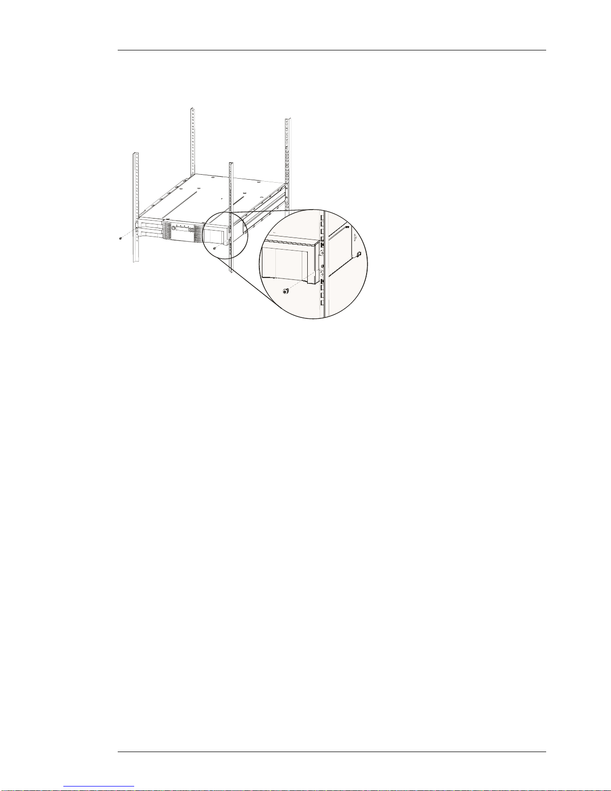
2.3 Rack stability
WARNING To reduce the risk of personal injury or damage to equipment:
Extend levelling jacks to the floor.
Ensure that the full weight of the rack rests on the levelling jacks.
Install stabilizing feet on the rack.
In multiple-rack installations, secure racks together.
Extend only one rack component at a time. Racks may become unstable
if more than one component is extended.
actiLib Library 2U – Quick Start Guide
Page 4 of 17

3 Unpacking the tape library
Before you begin, clear a work surface to unpack the library. Select an open 2U rack location allowing
easy access to the host server and an easily accessible power outlet.
CAUTION: If the temperature in the room where the library will be installed varies by more than 15º C
(30º F) from the room where the library was stored, allow the library to acclimate to the
surrounding environment for at least 12 hours before unpacking it from the shipping
container.
Unpacking the library:
1. Before opening and removing the library from the shipping container, inspect the container
for shipping damage. If you notice any damage, report it to the shipping company
immediately.
2. Open the box and remove the two rack rails (if included) and set aside.
3. Carefully remove the shipping materials from the top of the library. Remove the accessory
package and set aside.
4. Lift the library out of the carton and remove the bag from the library. Remove the foam
cushion from the back of the library. Save the packaging materials for future use.
CAUTION: Do not place the library on either end or sides as this may damage the library.
3.1 Identifying product components
Confirm that you have received the following:
Library
Terminator (not in all configurations)
SCSI cable (not in all configurations)
Power cord (not in all configurations)
Rack mount kit: (not in all configurations)
Documentation
Quick Start Guide
3.2 Removing the ship lock
Removing the shipping lock
IMPORTANT: The shipping lock, which prevents the robotic transport mechanism from moving during
shipment, must now be removed before the library is powered on.
The shipping lock is held in place with a label and is located in the top center of the library. After the
shipping lock is removed, it should be stored on the rear panel right side of the library for future use.
actiLib Library 2U – Quick Start Guide
Page 5 of 17

2
1
Figure 1 Shipping lock and label
2
1
Figure 2 Shipping lock and label on the rear panel
Figure 3 Shipping lock before transportation
3
4
5
2
1
actiLib Library 2U – Quick Start Guide
Page 6 of 17

3.3 Rackmounting the library
The library easily installs into a standard 19” rack system taking up 2U of space.
WARNING! The actiLib Library 2U weighs 15.6 kg without media.
To reduce the risk of personal injury or damage to the library:
1) observe local health and safety requirements and guidelines for manual material
handling,
2) obtain adequate assistance to lift and stabilize the library during installation or removal,
3) always remove all tapes to reduce the overall weight of the library.
Required tools:
1. #3 Phillips screwdriver
2. T10 Torx screwdriver (included in your shipment)
There are two sets of eight M6 screws in the accessory package that came with your library. The type
of rack that you have will determine the type of M6 screw that you will use.
To install the library:
3. Determine the location in you rack for your library to be installed and, using a pencil, mark
the location on each vertical rail in you rack.
4. Using the screws for your rack type, and a #3 Phillips screwdriver, secure one rail to each
side of the rack in your chosen rack location. Secure both the front and back of each rail to
the rack. The rails extend to fit a variety of rack depths. The correct orientation of the left
and right rails is shown in Figure 4.
Figure 4 Installing the rails into the rack
actiLib Library 2U – Quick Start Guide
Page 7 of 17

5. Using the Torx screwdriver, remove the screws on each side of your library. Shown in
Figure 5 (step 1).
Figure 5 Installing the mounting brackets and guide pulleys
2
3
1
6. Install the library guide pulleys on each side of the library using the 2 Torx screws included
in the rack kit (see Figure 5 step 2).
7. Install the mounting brackets of the library using the 4 Torxs screws included in the rack kit.
Shown in Figure 5 (step 3).
8. With library guide pulleys and mounting brackets installed, slide the library onto the rails.
9. Secure the library to the rack (see Figure 6) using a 3# Phillips screwdriver placed through
the small holes in the mounting bracket to tighten the M5 screw on each side of the library.
actiLib Library 2U – Quick Start Guide
Page 8 of 17

Figure 6 Securing the library to the rack
actiLib Library 2U – Quick Start Guide
Page 9 of 17

4 actiLib Library 2U overview
4.1 Front panel
Figure 7 Front panel overview
Number Description
1 Left Magazine
2 Power button.
Pressing the button will initiate a controlled Power Down of the unit (soft power down).
3 LED “Ready/Activity” (Green).
Illuminated when power is on. Blinking when there is tape or library robotics activity.
4 LED “Clean Drive” (Amber).
Illuminated when the tape drive has determined that a cleaning cartridge should be used.
Cleaning is only necessary when the library directs you to do so. Additional cleaning is not
necessary.
5 LED “Media Attention” (Amber).
Illuminated if the library has detected a condition that requires attention by the operator.
6 LED “Error” (Amber).
Illuminated if an unrecoverable tape drive or library error occurs. A corresponding error
message displays on the LCD screen (see for more information).
7 Control key “Cancel” button [X]
The CANCEL button is used to cancel a user action and return to the last menu item.
8 Control key “Previous” button [<]
The PREVIOUS button is used to navigate backward through menu items.
9 Right Magazins
10 Air vents
11 Control key “Enter” button [↵]
The ENTER button to go to a sub menu or execute an action.
12 Control key “Next” button [>]
The NEXT button is used to navigate through menu items.
13 Front panel LCD screen “OCP” display, consisting of 128 x 64 characters
The OCP screen displays actions and status information, menu items or error messages
equivalent to the operation mode.
14 Left Magazine with Mail slot
actiLib Library 2U – Quick Start Guide
Page 10 of 17

Table 1Front panel description
4.2 Rear panel
Figure 8 Back panel overview with one half height LTO SCSI tape drive
Number Description
1 Fan vent
2 Power connector: The library requires a 110/220 volt AC power connection
3 Tape drive tray 1
4 Tape drive tray 2
5 68-pin HD SCSI connectors
6 FC connector
7 Foil Product label
8 Drive LED
9 Ethernet port
10 Serial port
11 USB port (Host)
12 Shipping lock
Table 2Back panel description
Figure 9 Back panel overview with one half height FC tape drive
Same description as in table 2 except for the FC connectors and that the fan is moved
to the left of the FC connectors.
actiLib Library 2U – Quick Start Guide
Page 11 of 17

Figure 10 Back panel overview with one half height SAS tape drive
Same description as in table 2 except for the SAS connector.
actiLib Library 2U – Quick Start Guide
Page 12 of 17

5 Labeling tape cartridges
Attaching a barcode label to each tape cartridge enables the library and application software to identify
the cartridge quickly, thereby speeding up inventory time. Make it a practice to use barcode labels on
your tape cartridges.
IMPORTANT: The misuse and misunderstanding of bar code technology can result in backup and
restore failures. To ensure that your bar codes meet manufactures quality standards,
always purchase them from an approved supplier and never print bar code labels your
self.
Figure 9 Ultrium tape cartridge and proper bar code label placement
All rewritable data cartridges have a write-protect switch to prevent accidental erasure or overwriting of
data. Before loading a cartridge into the library, make sure the write-protect switch on the front of the
cartridge is in the desired position.
Number Description
1 Write-enabled
2 Write-protected
3 Write-protect switch
4 Barcode label
5 Insertion arrow
Figure 10 Write-protecting the Ultrium data cartridge
actiLib Library 2U – Quick Start Guide
Page 13 of 17

6 Magazines
Cartridges are stored in magazines. Up to 12 cartridges can be stored in each magazine.
Magazines may be removed and inserted individually.
The FlexStor II tape library has two removable magazines in the 2U library (see Figure 11 and Figure
12). Magazine access can be password protected. For safety reasons, the robotic motion is stopped
when a magazine is removed.
The magazines can be released using the Operator Control Panel (OCP) or the Remote Management
Unit (RMU) In case the OCP or RMU initiated process has failed or the library no longer has power a
manual emergency release is available.
13
14
18
16
19
17
15
21
20
Figure 11 Slot numbering right magazine
12
5
4
2
8
7
6
1*
3
9
11
10
* Mailslot
Figure 12 Slot numbering left magazine
6.1 Mailslot
Mailslots are used to import/export individual cartridges without interrupting library operation. The
command to open the mailslot may be denied if the robotics is busy with some operation. In that case
„Busy“ is displayed and the command has to be repeated once the robotics operation is finished.
actiLib Library 2U – Quick Start Guide
Page 14 of 17

7 Connecting the Library
NOTE: The LTO3 and LTO4 tape drives are Ultra 320 SCSI LVD device. Only cables and terminators
specified for Ultra320 use should be used.
WARNING! Approved power cord for your specific geographic region. Use of a non-manufacturer
approved power cord may result in:
1) not meeting individual country specific safety requirements;
2) insufficient conductor amp city that could result in overheating with potential personal
injury and/or property damage;
3) an unapproved power cord could fracture resulting in the internal contacts being
exposed, which potentially could subject the user to a shock hazard. Manufacturer
disclaims all liability in the event a non-manufacturer approved power cord is used.
Removebefore
operation!
Figure 13 Attaching the SCSI cable to the LTO3 full height drive
Removebefore
operation!
Figure 14 Attaching the terminator to the LTO3 full height drive
Removebefore
operation!
Figure 15 Attaching the power cable
actiLib Library 2U – Quick Start Guide
Page 15 of 17

7.1 SCSI installation
Power-off the unit and the host system before plugging in the SCSI cables. If your library includes
SCSI tape drives, connect the SCSI cables to the connectors on the drive sled.
1) Connect a jumper cable between the top SCSI connector of the bottom drive and the
bottom SCSI connector of the drive above it.
Repeat this step for the next drive on the SCSI bus. Secure the cable with the thumbscrews on the
connectors.
2). Terminate the last device on the SCSI bus using the appropriate SCSI terminator.
3). Connect a cable between the first drive on the SCSI bus and the host. NOTE: There are limitations
to the length of the SCSI cable. In typical installation, the total cable length should NOT exceed 9
meters / 30 feet
7.2 SAS installation
If your library includes tape drives with SAS interface, connect SAS cables to the tape drives.
Attach one end of the SAS cable to the SAS port on each drive. Attach the other end of the cable to
the host.
7.3 Fibre-channel installation
If your library includes fibre channel tape drives, connect fibre cables to the tape drives. Attach
one end of the fibre cable to the fibre port on each drive. Attach the other end of the cable to
the host, switch or hub.
7.4 Configuring the library
1) Connect your Ethernet cable to the Ethernet port at the rear of the library. The Ethernet connection
allows use of the Web Client.
2) Connect a power cord to the power connector at the rear of the library. US and European power
cords are supplied with the library.
3) Power-on the library.
4) Power up the host system.
5) Verify that each host can communicate with the library’s tape drives
f. Configure your library using the library’s operator panel.
actiLib Library 2U – Quick Start Guide
Page 16 of 17

8 Power ON/OFF the library
Part of the operator control panel is the Power On/Off button. Pressing this button will initiate a
controlled Power Down of the unit (soft landing). The following operations will take place before the
unit shuts down completely:
The display indicates with an appropriate message that the shutdown is in progress
The library controller finishes all ongoing loader and drive activities
The robotics is moved to its home position
The library controller switches off the power supply’s secondary side
To abort the shutdown process the user has to press Cancel within the first 3 seconds
Note: The shutdown process may be aborted by pressing Cancel within the first 3 seconds.
actiLib Library 2U – Quick Start Guide
Page 17 of 17
Table of contents
Other Actidata Storage manuals

Actidata
Actidata actiDisk RDX User manual

Actidata
Actidata actiLib Autoloader 1U Operating and maintenance instructions

Actidata
Actidata actiLib Autoloader 2U Troubleshooting guide

Actidata
Actidata actiNAS XL 2U-12 User manual

Actidata
Actidata actiNAS Cube SL User manual

Actidata
Actidata actiNAS SL 1U-4 User manual

Actidata
Actidata actiNAS BB212-3 User manual

Actidata
Actidata Ti-NAS QT-6 User manual

Actidata
Actidata actiTape LTO-3 User manual

Actidata
Actidata actiLib Autoloader 4U User manual