Actidata actiLib Kodiak 3407 User manual

actiLib Kodiak 3407
Quick Start Guide
Document Purpose
This document provides a product overview and information to install and the initial setup
of the actiLib Kodiak 3407 Scalable Tape Library. The instruction is intended for trained
System Administrators and Users who need physical and functional knowledge of the
actiLib Kodiak 3407 library.
actidata Storage Systems GmbH - 07/12/2018

2/ 42
Revision
Change No.
Author
Verified by
Release
Date
yyyy-mm-dd
Description
1.0
0
Timo Kühne
2018-06-06
Initial Revision

3/ 42
Inhaltsverzeichnis
Document Purpose...................................................................................................................................1
Introduction.................................................................................................................................................. 5
Document Purpose...................................................................................................................................5
General Warnings ........................................................................................................................................ 6
Document Conventions:.......................................................................................................................... 6
General Product Warnings ..................................................................................................................... 6
Product Overview ......................................................................................................................................10
Supported Library Configurations –Rackmount Installation ....................................................... 10
Supported Module Configurations with Legacy Serial ADI Drive Sleds ......................................13
Supported Tape Drives..........................................................................................................................13
Front Panel ..............................................................................................................................................14
Rear Panel ...............................................................................................................................................15
Element Numbering ...............................................................................................................................16
Installing the Library ................................................................................................................................ 17
Planning Installation .............................................................................................................................17
Location Requirements .........................................................................................................................17
SAS Configuration Requirements........................................................................................................17
Fibre Channel Configuration Requirements......................................................................................18
Planning Module and Rack Layout......................................................................................................19
Internal IP Range Selection.................................................................................................................19
Host Preparation ....................................................................................................................................20
Installation Precautions .......................................................................................................................21
Unpacking Base Module and Expansion Modules ............................................................................22
Identifying Library Module Components...........................................................................................24
Preparing Top and Bottom Modules ...................................................................................................24
Installing Modules in a Rack................................................................................................................ 27
Aligning and Connecting Modules.......................................................................................................29
Installing Tape Drives ........................................................................................................................... 31
Connecting Fibre Channel Cables .......................................................................................................31
Connecting SAS Cables .........................................................................................................................31
Powering On the Library.......................................................................................................................32
Using the Configuration Wizard ..........................................................................................................32
Verifying the Host Connection.............................................................................................................32
Loading Tape Cartridges .......................................................................................................................32
Labeling Tape Cartridges ..................................................................................................................33
Using the Mailslot ...............................................................................................................................33
Bulk Loading Magazines.................................................................................................................... 34
Verifying the Installation......................................................................................................................34
Configuring Additional Features .........................................................................................................34
Tape Cartridges and Magazines ..............................................................................................................35
Using and Maintaining Tape Cartridges.............................................................................................35

4/ 42
Labeling Tape Cartridges ..................................................................................................................35
Write Protecting Tape Cartridges.................................................................................................... 36
Initial Setup of the Library.......................................................................................................................37
Using the OCP .........................................................................................................................................37
Using the RMI .........................................................................................................................................37
Logging into the Library .......................................................................................................................38
Using the Initial Configuration Wizard on the OCP.........................................................................38
Get help........................................................................................................................................................ 42

5/ 42
Introduction
Document Purpose
This document provides information to install, operate, upgrade, service and troubleshoot the actiLib
Kodiak 3407 Scalable Tape Library. The instructions are intended for the trained System Administrators
and trained Users who need physical and functional knowledge of the actiLib Kodiak 3407 library.
WARNING
•Only trained personnel should operate this equipment.
•Read all documentation and procedures before installation or operation.
•The actiLib Kodiak 3407 must only be installed in a restricted Area.
•Only personnel with technical and product safety training should be provided access to the
library.
•For safety reasons the default administrator PIN on the Operator Control Panel needs to be
changed during initial configuration.
•Hazardous moving parts exist inside this product. Do not insert tools or any parts of your
body into the interior of the library while the mailslot or magazine is pulled out.
•Do not insert any tools or any parts of your body into drive bay openings or any other
openings of an operating system.
AVERTISSEMENT
Cet équipement ne doit être utilisé que par un personnel formé. Lisez la totalité
de la documentation et des procédures avant toute installation ou utilisation. Ce produit est conçu
pour l'installation et l'utilisation dans un rack d'ordinateur avec les portes avant et arrière fermées
et sécurisées. Seul un personnel avec la formation technique et de sécurité des produits est autorisé
à accéder à la bibliothèque. Ce personnel est désigné par utilisateurs dans la totalité de ce
document.
Pour des raisons de sécurité le PIN d'administrateur par défaut doit être changé au cours de la
configuration initiale.
Les pièces mobiles dangereuses existent à l'intérieur de ce produit. N'insérez pas d'outils ni partie du
corps dans les ouvertures d'un système en marche.
The main components are:
▪actiLib Kodiak 3407 BTL (Base Module)
▪actiLib Kodiak 3407 ETL (Expansion Module)
Product Warranty Caution
The customer should only perform the service and repair actions on the tape library components as
described in this document. Any other actions needed should only be performed by an authorized service
center.
The warranty for the tape library shall not apply to failures of any unit when:
▪The tape library is repaired or modified by anyone other than the manufacturer’s personnel or approved
agent.
▪The tape library is physically abused or used in a manner that is inconsistent with the operating
instructions or product specification defined by the manufacturer.
▪The tape library fails because of accident, misuse, abuse, neglect, mishandling, misapplication,
alteration, faulty installation, modification, or service by anyone other than the factory service center or

6/ 42
its approved agent.
▪The tape library is repaired by anyone, including an approved agent, in a manner that is contrary to the
maintenance or installation instructions supplied by the manufacturer.
▪The manufacturer's serial number tag is removed.
▪The tape library is damaged because of improper packaging on return.
Warranty will become immediately void in the event of unauthorized repairs or modifications.
General Warnings
Document Conventions:
WARNING
Indicates that failure to follow directions could result in bodily harm or
death.
CAUTION
Indicates that failure to follow directions could result in damage to
equipment or data.
!
IMPORTANT
Provides clarifying information or specific instructions.
NOTE
Provides additional information.
TIP
Provides helpful hints and shortcuts.
AVERTISSEMENT
Le non-respect de ces instructions expose l'utilisateur à
des risques
potentiellement très graves.
ATTENTION
Le non-respect de ces instructions comporte des risques tant pour le
matériel que pour les informations qu’il contient.
!
IMPORTANT
Apporte une clarification ou fournit des instructions spécifiques.
REMARQUE
Fournit des informations complémentaires..
ASTUCE
Conseils et raccourcis utiles.
General Product Warnings
DANGER
High voltage
Risk of electric shock
▪Do not remove power supply covers.No user-serviceable parts are
inside unless specifically identified.
▪Refer servicing to qualified service personnel.
DANGER
Tension élevée
7/ 42
Risque de choc électrique
•Ne pas retirer le couvercle de l'alimentation. Aucune pièce
réparable par l'utilisateur ne se trouve à l'intérieur à moins que
celle-ci ne soit spécifiquement identifiée.
•Confier toute réparation à un personnel qualifié.
MECHANICAL
HAZARD
Danger Risk of hand pinching, can trap hands, fingers
and cause serious injury. Keep hands clear during
operation.
DANGER
MÉCANIQUE
Danger Risque de se coincer la main et de se coincer les
mains ainsi que les doigts le tout pouvant entrainer de
graves blessures. Gardez les mains à l'écart pendant le
fonctionnement.
WARNING
Product Weight
Risk of personal injury
Before lifting a module:
▪Observe local health and safety requirements and
guidelines for manual material handling.
▪Remove all tapes to reduce the weight.
▪Remove all tape drives to reduce the weight.
▪Obtain adequate assistance to lift and stabilize the
module during installation or removal.
Risk of damage to devices
When placing a module into or removing the module from
a rack:
▪Extend the rack’s levelling jacks to the floor.
▪Ensure that the full weight of the rack rests on the
levelling jacks.
▪Install stabilizing feet on the rack.
▪Extend only one rack component at a time.
8/ 42
AVERTISSEMENT
Poids du produit
Risque de blessure
Avant de soulever un module:
▪Respectez les règles locales de santé et de sécurité au
travail ainsi que les instructions concernant la
manipulation du matériel.
▪Retirez toutes les cartouches à bande pour réduire le
poids
▪Retirez toutes les lecteurs de bande pour réduire le
poids
▪Faites-vous assister de manière adéquate pour soulever
et stabiliser le périphérique pendant l’installation ou le
retrait.
Risque d'endommager les périphériques
Lors de l'insertion d'un module dans un rack ou du retrait
d’un module d'un rack:
▪Les vérins de mise à niveau doivent être en contact
avec le sol.
▪Les vérins de mise à niveau doivent supporter tout le
poids du rack.
▪Installez le kit de mise à niveau sur le rack.
▪Déployez un seul élément de rack à la fois. Si vous
déployez plusieurs éléments à la fois, vous risquez de
compromettre la stabilité du rack.
CAUTION
Static Sensitive
Risk of damage to devices
▪A discharge of static electricity damages static-sensitive devices or
micro circuitry.
▪Proper packaging and grounding techniques are necessary
precautions to prevent damage.
ATTENTION
Électricité statique
Risque d'endommager les périphériques par une décharge
d’électrostatique.
▪Une décharge d'électricité statique peut endommager les circuits
imprimés du système ou les autres périphériques sensibles aux
décharges électrostatiques.
▪Un emballage approprié et une mise à la terre constituent les
précautions nécessaires pour éviter tout dommage.
NOTE
▪Ventilation –Place the product in a location that does not interfere with
proper ventilation.
▪Heat –Place the product in a location away from heat sources.
▪Power sources –Connect the product to a power source only of the type
directed in the operating instructions or as marked on the product.
▪Power cord protection –Place the AC line cord so that it is not possible to be
walked on or pinched by items placed upon or against it.
▪Object and liquid entry –Insure that objects do not fall onto and that liquids
are not spilled into the product’s enclosure.

9/ 42
REMARQUE
▪Ventilation –Placez le produit dans un endroit qui
n'interfère pas avec une ventilation approprié.
▪Chaleur –Placez le produit dans un endroit loin de sources
de chaleur.
▪Alimentation électrique –Veuillez ne brancher le produit
qu’à une source d'alimentation correspondant aux
instructions figurant dans le mode d'emploi ou comme
directement indiqué sur le produit.
▪Protection du cordon d'alimentation –Placez le cordon
d'alimentation principal de sorte qu'il ne soit pas possible de
marcher dessus ou d'être écrasé par des objets placés sur
ou contre.
▪Pénétration d'objets et de liquide –S'assurez que des
objets ne tombent pas sur le boîtier du produit et que des
liquides ne soient pas déversés dans le boîtier du produit

10 / 42
Product Overview
WARNING
Only trained personnel should operate this equipment. Read all
documentation and procedures before installation or operation. This
product is intended for installation and operation in a restricted area.
Only personnel with technical and product safety training should be
provided access to the library. Such personnel are referred to as users
throughout this document. Do not insert any tools or any part of your
body into openings of an operating system.
AVERTISSEMENT
Cet équipement ne doit être utilisé que par un personnel formé. Lisez la totalité
de la documentation et des procédures avant toute installation ou utilisation. Ce produit est conçu
pour l'installation et l'utilisation dans un rack d'ordinateur avec les portes avant et arrière fermées
et sécurisées. Seul un personnel avec la formation technique et de sécurité des produits est autorisé
à accéder à la bibliothèque. Ce personnel est désigné par utilisateurs dans la totalité de ce
document. N'insérez pas d'outils ni partie du corps dans les ouvertures d'un système en marche.
All actiLib Kodiak 3407 installations begin with the 3U high Base Module, with capacity for 32 tape cartridges
and 3 half-height LTO tape drives.
actiLib Kodiak 3407 is expandable, allowing a user to grow their tape storage capacity as their data
requirements increase. As data storage needs grow, actiLib Kodiak 3407 can also grow by adding one or
more 3U high Expansion Modules.Each Expansion Module provides an additional 40 tape cartridges and
supports an additional 3 half-height LTO tape drives.
Up to 6 Expansion Modules can be added to a Base Module, bring the total library capacity to 272 tape
cartridges and 21 half-height LTO tape drives.
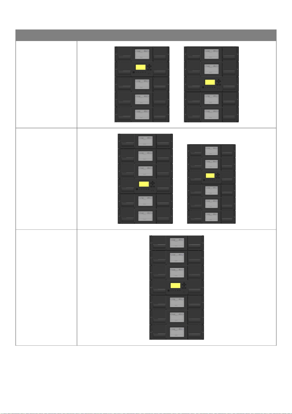
Supported Library Configurations –Rackmount Installation
All actiLib Kodiak 3407 Libraries start with a Base Module. Up to 6 Expansion Modules can be added as
needed to support customer requirements. The architecture has been designed to support a maximum of 3
Expansion Modules above and 3 Expansion Modules below. The Base Module must be mounted with 9U
of empty space about and 9U of empty space below to ensure a full stack can be installed. Table 1 shows
the supported configurations for libraries ranging from one to seven total modules.
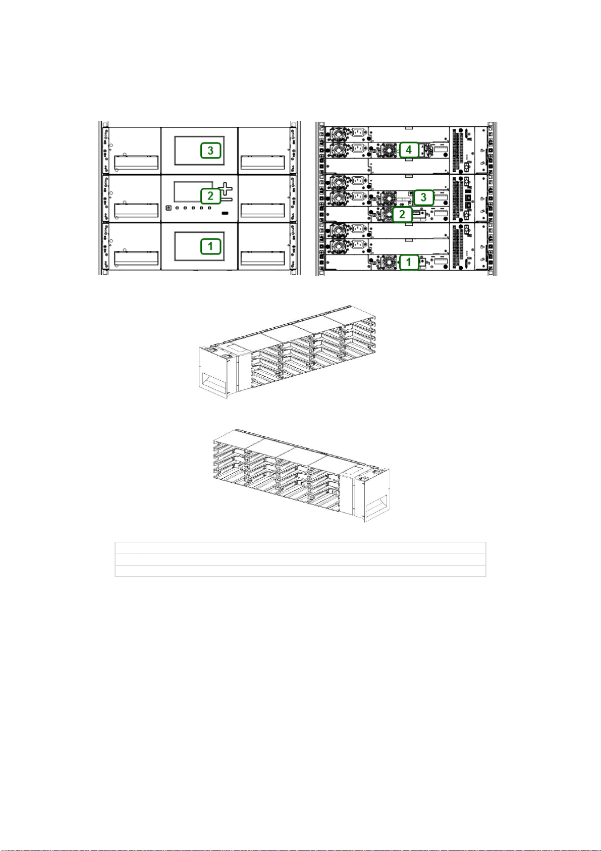
The Base Module is depicted by the following image with the Operator Control Panel shown in yellow:
Each Expansion Module is represented by the following image with a large clear viewing window in the
center.

11 / 42
Module Quantity
Supported Library Configurations
1 Module Library
Base Module
2 Module Library
Base Module
1 Expansion Module
3 Module Library
Base Module
2 Expansion Modules
4 Module Library
Base Module
3 Expansion Modules
12 / 42
Module Quantity
Supported Library Configurations
5 Module Library
Base Module
4 Expansion Modules
6 Module Library
Base Module
5 Expansion Modules
7 Module Library
Base Module
6 Expansion
Modules
13 / 42
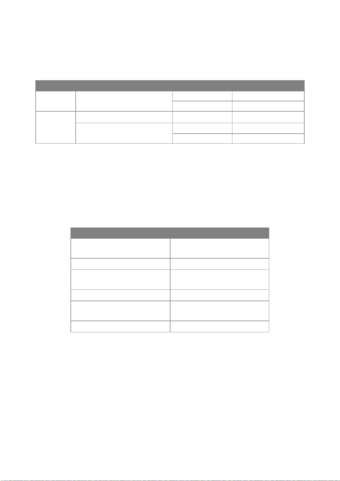
Supported Module Configurations with Legacy Serial ADI Drive Sleds
actiLib Kodiak 3407 supports serial ADI sleds from actiLib LTO 1U/2U/4U and actiLib Kodiak 6807 Tape
Libraries. One drive power board (DC-DC converter) is required in each module that includes one or more
serial ADI drive sleds. Table 2 describes the supported serial ADI configurations for each module type –
Base Module and Expansion Module.
Module Type
Power Supplies
Drive Power Boards
Tape Drives
Base
1 (standard)
or
2 (redundant)
0 (standard)
0
1
Up to 3
Expansion
0 (standard)
0 (standard)
0
1 (required with 1 or more drives)
or
2 (redundant)
0 (standard)
0
1
Up to 3
Supported Tape Drives
actiLib Kodiak 3407 was developed to integrate industry-standard LTO Ultrium tape drives from both HP
and IBM.
Mixed drive generations and mixed interfaces are supported within a single library and within a single
module.
Listed below are the tape drives that have been implemented and qualified for use in actiLib Kodiak 3407.
IBM LTO Drives
HP LTO Drives
LTO-6 Half-Height FC Single Port
LTO-6 Half-Height FC Dual Port
LTO-6 Half-Height FC Dual Port
LTO-6 Half-Height SAS Dual Port
LTO-6 Half-Height SAS Dual Port
LTO-7 Half-Height FC Single Port
LTO-7 Half-Height FC Dual Port
LTO-7 Half-Height FC Dual Port
LTO-7 Half-Height SAS Dual Port
LTO-7 Half-Height SAS Dual Port
LTO-8 Half-Height FC Single Port
LTO-8 Half-Height FC Dual Port
LTO-8 Half-Height FC Dual Port
LTO-8 Half-Height SAS Dual Port
LTO-8 Half-Height SAS Dual Port
14 / 42
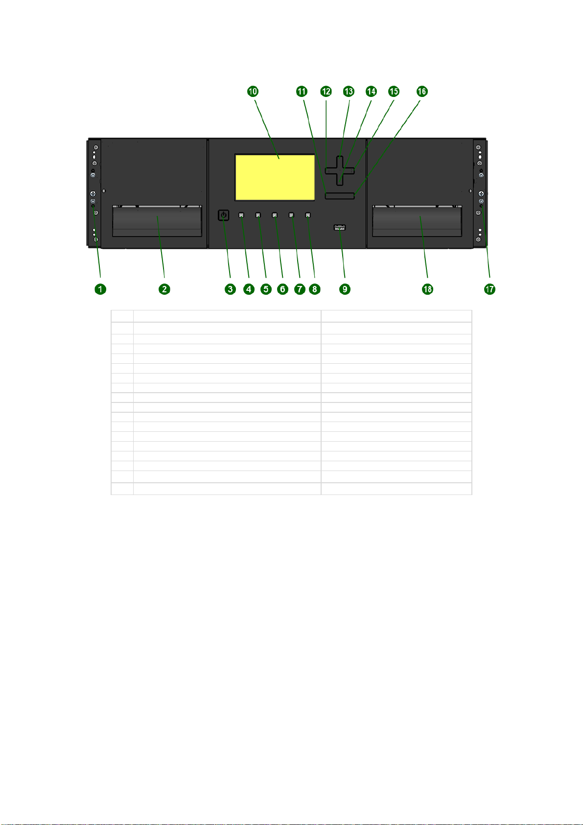
Front Panel
1
Left Magazine Emergency Release Access Hole
2
Left Magazine Access Handle
3
Power Button
Base Module Only
4
Unit Identification LED, Blue
Base Module Only
5
Ready LED, Green
Base Module Only
6
Clean LED, Amber
Base Module Only
7
Attention LED, Amber
Base Module Only
8
Error LED, Amber
Base Module Only
9
USB Port
Base Module Only
10
Operator Control Panel (OCP) Display
Base Module Only
11
Back/Return Button
Base Module Only
12
Navigation Button - Left
Base Module Only
13
Navigation Button –Up
Base Module Only
14
Navigation Button –Down
Base Module Only
15
Navigation Button –Right
Base Module Only
16
Enter Button
Base Module Only
17
Mailslot/Right Magazine Access Handle
18
Right Magazine Emergency Release Access Hole
15 / 42
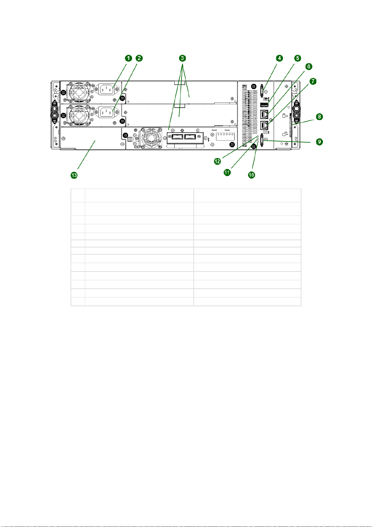
Rear Panel
1
Power Supply 1
Standard on Base Module
Optional on Expansion Module
2
Power Supply 2
Optional on Base Module
Optional on Expansion Module
3
Half-Height Tape Drive Bays
4
Upper Expansion Module Connection Port
5
USB Port
Optional on Base Module Only
6
Ethernet Port A
Base Module Only
7
Ethernet Port B
Optional on Base Module Only
8
Module Alignment Mechanism
9
Lower Expansion Module Connection Port
10
Unit Identifier LED, Blue
11
Controller Error LED, Yellow
12
Controller Health Status LED, Green
13
Product Serial Number Tag Location
16 / 42
Element Numbering
The library will generally display logical element numbering of modules, storage slots and tape drives
starting with number one from the bottom up.
1
Left Magazine
2
Right Magazine, Mailslot Disabled
3
Right Magazine, Mailslot Enabled
17 / 42
Installing the Library
Planning Installation
•Choose a location for the library. See “Location Requirements”.
•Plan the SAS or Fibre Channel configuration and obtain the necessary cables. See “SAS
Configuration Requirements”or “Fibre Channel Configuration Requirements”.
•For rack installations, plan the rack layout. See “Planning the Module and Rack Layout”.
•Internal IP Range Selection
Location Requirements
NOTE
•The library was designed for both rack and tabletop installation.
•Rack installations must use the provided rack rails.
•1 Module tabletop installations require no additional hardware.
•2 Module (Base Module + 1 Expansion Module) tabletop installations must
use the optional table top kit.
•Select a location with access to the host server.
•Choose a location that meets the criteria in the table below.
Criteria
Definition
Rack Requirements
Standard 19-inch rack (minimum depth of 1 meter) with an appropriate # of U’s
(Rack Units) of clearance for the planned module quantity
Rack Space
Requirements
3U for the Base Module and 3U for each Expansion Module
Room Temperature
10-35º C (50-95º F)
Power Source
AC Power Voltage: 100-240 VAC
Line Frequency: 50-60 Hz
Library Located near AC Outlet(s)
The AC power cord is the library’s main AC disconnect device and must be easily
accessible at all times.
Air Quality
Place the library in an area with minimal sources of particulate contamination
Avoid areas near frequently used doors and walkways, stacks of supplies that
collect dust, printers, and smoke-filled rooms
Excessive dust and debris can damage tapes and tape drive
Humidity
20-80 percent RH non-condensing
SAS Configuration Requirements
Serial Attached SCSI (SAS) is a computer bus technology mainly used to transfer data to and from storage
devices, including disk drives and tape drives. SAS is designed to transfer data at up to 6 Gbps.
SAS uses serial connections, with a direct connection between the host server and each of the storage
devices. This eliminates the need to configure SCSI busses and assign SCSI IDs, as is required for parallel
SCSI devices.
The host server must have a SAS Host Bus Adapter (HBA) with an external connector. The HBA uses
multiple Logical Unit Numbers (LUNs) to communicate with the library. Verify that your HBA supports
multiple LUNs, as most RAID controllers do not. Most SAS HBA ports have four SAS channels. A tape
18 / 42
drive uses one channel, so each HBA port can support up to four tape drives. You can use a cable with one
connector on each end, but only one channel will be used.
Supported speeds by drive generation are shown in the table below.
Supported SAS Speeds
LTO Generation
Supported Speeds
LTO-6
1.5 Gbps, 3 Gbps, 6 Gbps
LTO-7
1.5 Gbps, 3 Gbps, 6 Gbps
LTO-8
1.5 Gbps, 3 Gbps, 6 Gbps
CAUTION
High quality SAS cables rated at the transfer rate the SAS drives are
required. Always verify that the SAS cable you are using is rated for the
data transfer speed of the interface of your components. SAS cables
described as "equalized" may not support 6 Gb/s data rates and should
not be used with LTO-5 or later generation tape drives unless these
cables are verified for 6 Gb/s data rates.
CAUTION
The library has one or more mini-SAS connectors on each SAS tape
drive. Mini-SAS connectors are keyed. Do not force a SAS cable’s mini-
SAS connector into the tape drive as it might be keyed differently.
A SAS tape drive is identified by a unique identifier called a World Wide Name (WWN) or World Wide
Identifier (WWID). The library assigns the WWID to the drive bay. When a tape drive is replaced, the WWID
is re-assigned to the new tape drive.
The operating system tracks the WWID for the tape drive on each HBA channel. Each of the drive
connectors on the fan-out cable is associated with an HBA channel. Once a tape drive has been plugged
in, it should remain on the same channel to retain the association between the HBA channel and WWID.
Fibre Channel Configuration Requirements
The Fibre Channel (FC) tape drive can be connected directly to the server with a Host Bus Adapter (HBA)
or through a storage area network (SAN).
The installation requires one Fibre Channel cable for each tape drive. The tape drives all utilize an LC-
style connector. Some drives will have two FC ports, but only one cable connection is needed per drive.
The cable can be connected to either drive FC port.
Supported speeds by drive generation are listed in the table below.
Table 1: Supported Fibre Channel Speeds
LTO Generation
Supported Speeds
LTO-6
2 Gbps, 4 Gbps, 8 Gbps
LTO-7
2 Gbps, 4 Gbps, 8 Gbps
LTO-8
2 Gbps, 4 Gbps, 8 Gbps
NOTE
▪Use an appropriate HBA for your tape drive due to performance
requirements.
A lower Gbps HBA might result in performance degradation when moving
highly compressible data to a higher Gb tape drive.
▪In a SAN installation, all switches between the host and the library must be of
the appropriate type.
A lower Gb switch in the path may result in performance degradation.
Configure zoning so only the backup servers may access the library.
19 / 42
Planning Module and Rack Layout
If possible, install the Base Module in the middle of the rack to provide space for the permitted 3 Expansion
Modules above and 3 Expansion Modules below. See 5.1 Supported Library Configurations for
additional details.
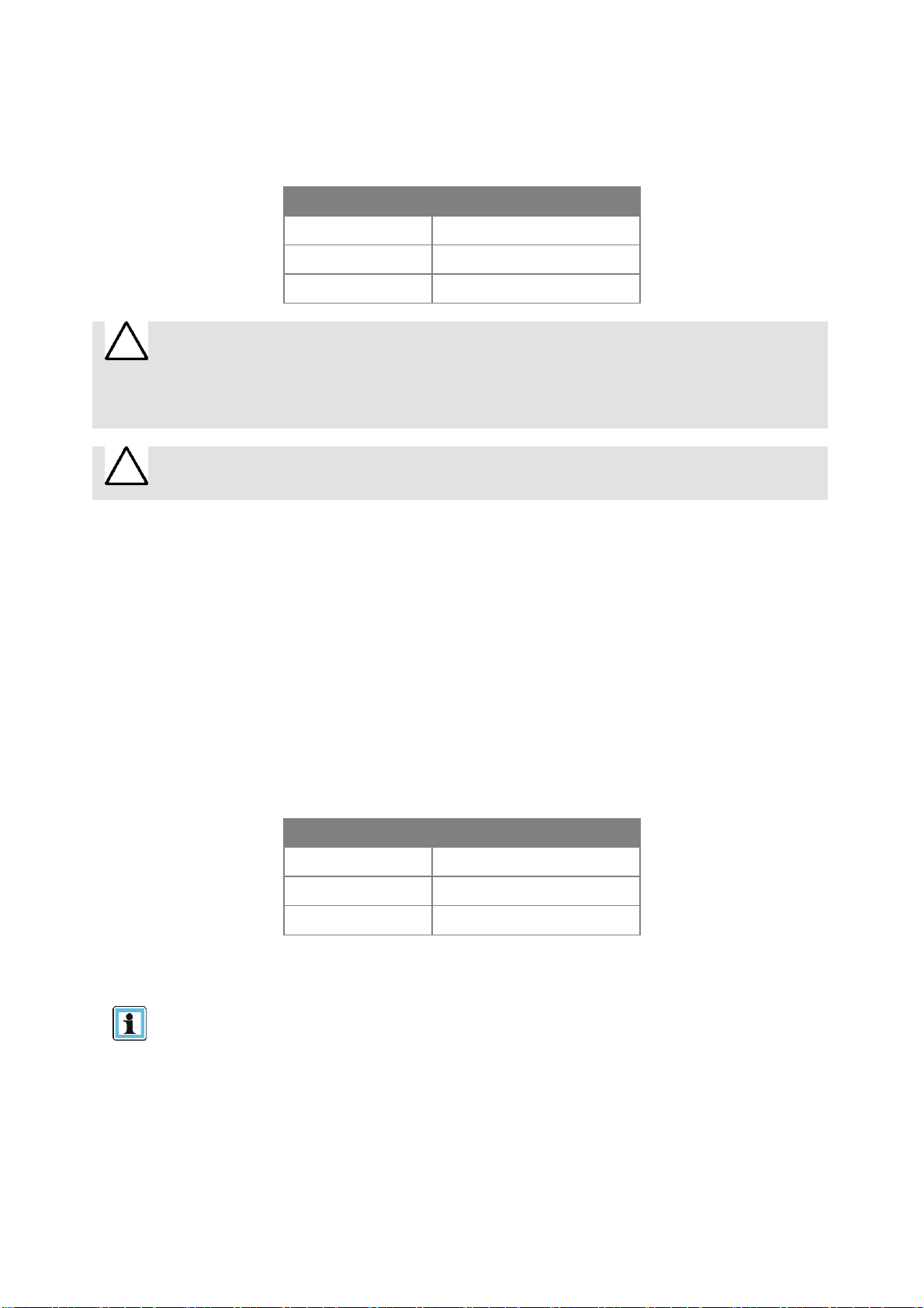
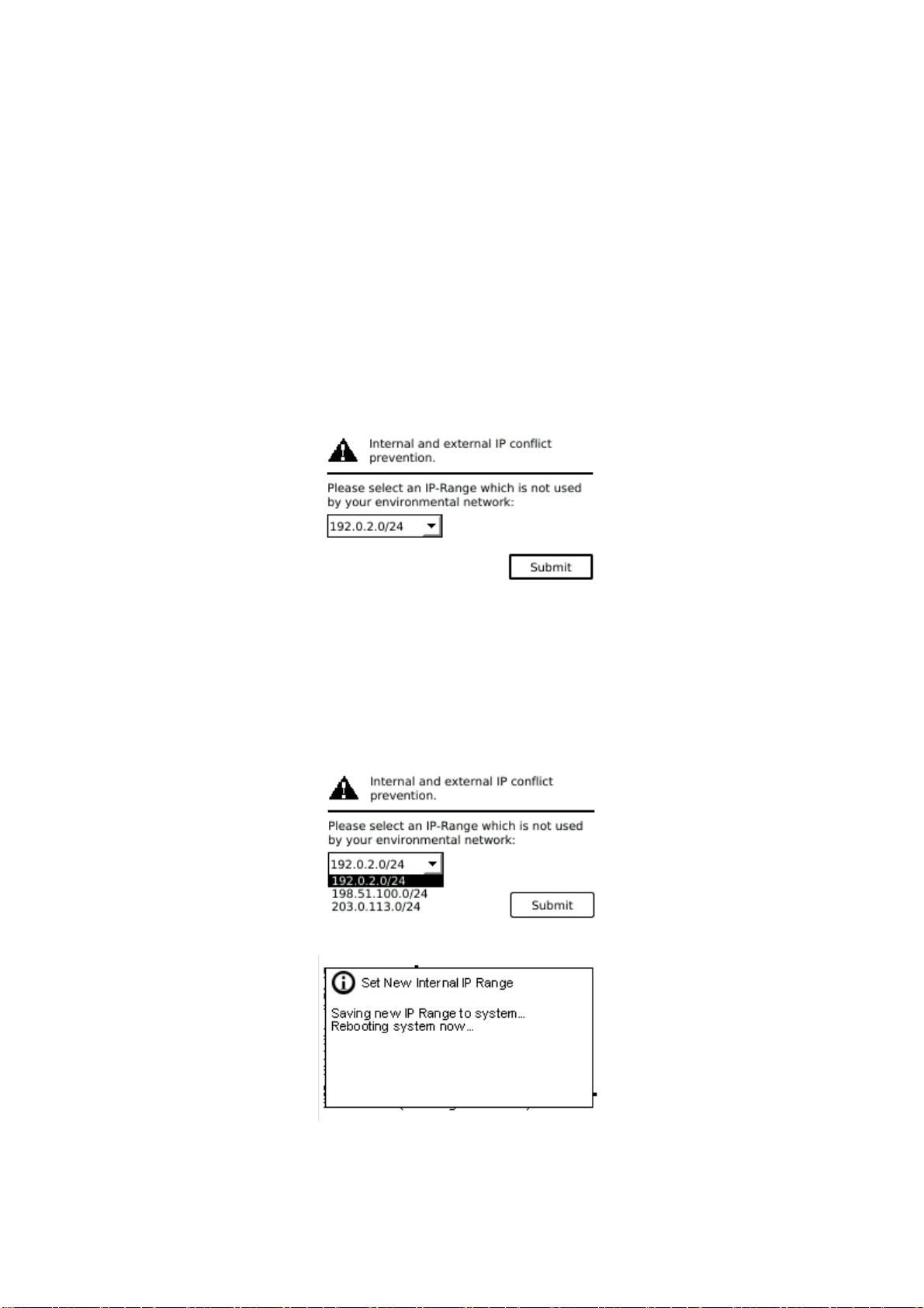
Internal IP Range Selection
For internal communication between modules the tape library uses an Ethernet connection with an internal
IP address range. To prevent any conflict between the internal IP address range and the external IP
addresses it is required to select the internal IP range before the tape library gets connected to the external
Ethernet port.
Therefore a file which contains the internal IP range is stored onto the Base Module backplane:
/opt/storage/mfg/stack/network.range and LCM /opt/storage/configuration/network.range
The Values must be in the following format: RANGE=192.0.2
Please note: the last section of the IP address is not set because it will be set internally.
The file will be created through the Operator Control Panel (OCP) IP Range selection page when the Stack
starts for the very first time or if the unit was reset to Manufacturing Defaults / Reset via OCP or Remote
Management Interface (RMI).

20 / 42
Host Preparation
CAUTION
Static Sensitive
Risk of damage to devices
▪A discharge of static electricity damages static-sensitive devices or
micro circuitry.
▪Proper packaging and grounding techniques are necessary
precautions to prevent damage.
ATTENTION
Électricité statique
Risque d'endommager les périphériques par une décharge
d’électrostatique.
▪Une décharge d'électricité statique peut endommager les circuits
imprimés du système ou les autres périphériques sensibles aux
décharges électrostatiques.
▪Un emballage approprié et une mise à la terre constituent les
précautions nécessaires pour éviter tout dommage.
Follow these general guidelines:
▪Check with a system administrator before powering off the host computer.
▪For a SAS library, confirm availability or install a SAS HBA that supports multiple LUNs.
▪For a direct-attach Fibre Channel library, confirm availability of install an FC HBA.
▪For connection of a Fibre Channel library through a compatible switch, verify that sufficient ports are
available.
Table of contents


