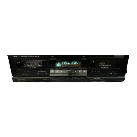
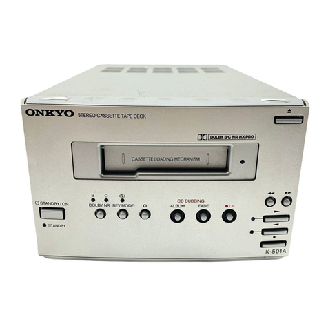
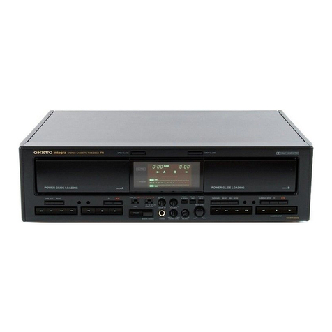
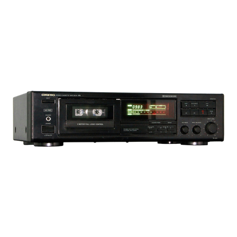
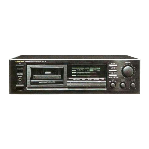
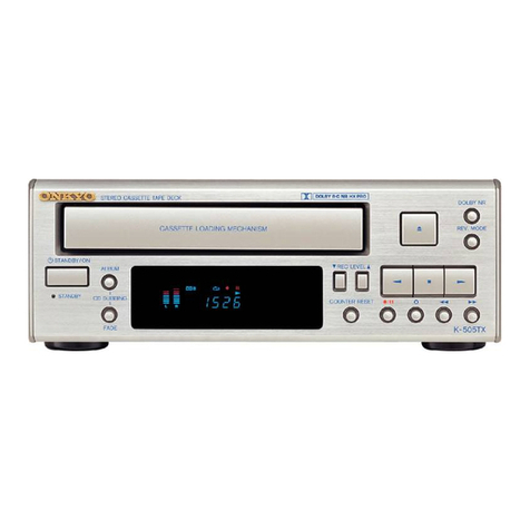
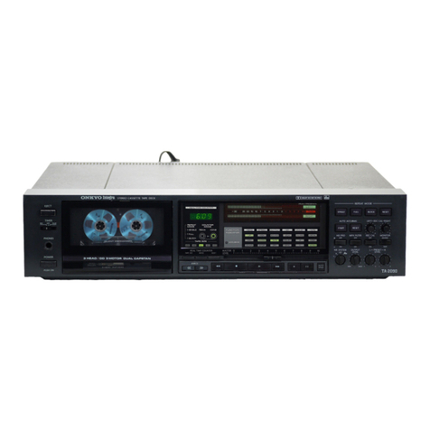
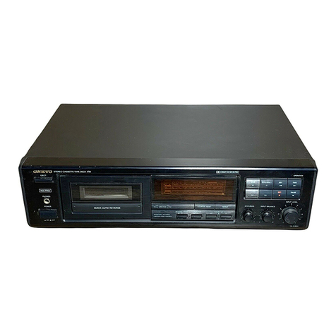
Onkyo TA-6510 User manual

ONKYO.
TA-6510
Stereo
Cassette
Tape
Deck
Instruction
Manual
DUAL
CAP?
STAN
i:
J
3
HEAD
/
3
MOTOR
FULL
LOGIC
CONTROL

Th
an
K
yo
U
for
your
purchase
of
the
Onkyo
TA-6510
cassette
tape
deck.
Please
read
this
manual
thoroughly
before
making
connections
and
turning
power
on.
Follow
these
instructions
to
obtain
optimum
perfor-
mance
and
maximum
listening
enjoyment
from
your
new
TA-6510.
Please
retain
this
manual
for
future
reference.
Features
=
Three-Motor,
Closed
Loop,
Dual
Capstan
Configuration
Three-motor
transport
provides
full-logic
operation,
excep-
tional
durability
and
the
precise
tape
movement
needed
for
ac-
curate
reproduction.
Its
closed-loop,
dual-capstan
drive
and
metal-mounted
cassette
holder
assure
maximum
tape-to-head
contact
and
suppression
of
any
minute
intemal
resonances.
@
Three
Heads,
with
PC-OCC
Wire
Head
Windings
Three
heads
(record,
playback,
and
erase)
give
you
maximum
recording
and
playback
efficiency,
and
let
you
monitor
the
playback
as
you
record.
The
gap-width
of
each
head
is
differ-
ent,
so
each
head
is
optimized
for
its
specific
job.
PC-OCC
(single-crystal
oxygen-free
copper
of
the
highest
purity)
wire
head
windings
assure
you
of
virtually
no
signal
loss,
with
the
absolute
minimum
amount
of
distortion
during
transmission.
@
Onkyo’s
Proprietary
Accubias
The
tape
type
selectors
on
most
cassette
decks
don’t
take
into
account
thé
minute
gradations
which
exist
between
tape
brands.
Onkyo’s
Accubias
eliminates
this
deficiency
by
allow-
ing
you
to
fine
tune
the
recording
bias,
and
bring
out
the
wid-
est,
flattest
frequency
response
possible
with
any
cassette
tape.
@
One-touch
CD
Synchro
Recording
Onkyo’s
one-touch
CD
synchronized
recording
lets
you
ef-
fortlessly
and
accurately
record
your
favorite
compact
discs
when
your
cassette
deck
is
connected
to
certain
Ricompatible
Onkyo
CD
players.
Reinforced
Chassis
Reinforced
Cassette
Holder
Silent
Tape
Transport
with
Microcomputer
Control
AEI
transformer
Dolby
HX
Pro,
B/C
noise
reduction
Switchable
MPX
filter
Real-time
tape
counter
Auto
monitor
system
Full/A-B
block
repeat
Forward
and
Reverse
Skip
Function
Large
FL
display
with
two
13-segment
peak-level
meters
Peak-hold
to
set
accurate
record/playback
levels
Ri
remote
control
system
compatible
Supplied
accessories
2
Audio
connection
cable
e
For
models
having
a
power
cord
with
a
polarized
plug
CAUTION:
TO
PREVENT
ELECTRIC
SHOCK,
MATCH
WIDE
BLADE
OF
PLUG
TO
WIDE
SLOT,
FULLY
INSERT.
e
Sur
les
modéies
don’t
la
fiche
est
polarisée
ATTENTION:
POUR
EVITER
LES
CHOCS
ELECTRIQUES,
INTRODUIRE
LA
LAME
LA
PLUS
LARGE
DE LA
FICHE
DANS
LA
BORNE
CORRESPONDANTE
DE
LA
PRISE
ET
POUSSER
JUSQ’
AU
FOND.
Replacement
and
mounting
of
an
AC
plug
on
the
power
supply
cord
of
this
unit
should
be
performed
only
by
qualified
service
personnel.
IMPORTANT:
The
wires
in
the
mains
lead
are
colored
in
accordance
with
the
following
code:
Blue:
Neutral
Brown:
Live
As
the
colors
of
the
wires
in
the
mains
lead
of
this
unit
may
not
correspond
with
the
colored
markings
identifying
the
terminals
in
your
plug,
proceed
as
follows:
The
wire
which
is
colored
blue
must
be
connected
to
the
terminal
which
is
marked
with
the
letter
N
or
colored
black.
The
wire
which
is
colored
brown
must
be
connected
to
the
termi-
nal
which
is
marked
with
the
letter
L
or
colored
red.
This
apparatus
complies
with
the
requirements
of
EC
direc-
tive
87/308/EEC.
Dolby
noise
reduction
and
HX
Pro
headroom
extension
manu-
factured
under
license
from
Dolby
Laboratories
Licensing
Cor-
poration.
HX
Pro
onginated
by
Bang
and
Olufsen.
‘‘Dolby,”’
the
double-
D
symbol
and
‘‘HX
PRO”’
are
trademarks
of
Dolby
Labora-
tories
Licensing
Corporation.
WARNING
‘‘TO
REDUCE
THE
RISK
OF
FIRE
OR
ELECTRIC
SHOCK,
DO
NOT
EXPOSE
THIS
APPLIANCE
TO
RAIN
OR
MOIS-
CAUTION
‘*TO
REDUCE
THE
RISK
OF
ELECTRIC
SHOCK,
DO
NOT
REMOVE
COVER
(OR
BACK).
NO
USER-SER
VICEABLE
PARTS
INSIDE.
REFER
SERVICING
TO
QUALIFIED
SER
VICE
PERSONNEL.”’
Oy
pecs
RISK
OF
ELECTRIC
SHOCK
ol@mm,
102
Gm)
4
4,
|
e
The
lightning
flash
with
arrowhead
symbol,
within
an
equilateral
triangle,
is
intended
to
alert
the
user
to
the
presence
of
uninsulated
‘*dangerous
voltage’’
within
the
product’s
en-
closure
that
may
be
of
sufficient
magnitude
to
constitute
a
risk
of
electric
shock
to
persons.
e
The
exclamation
point
within
an
equilateral
tri-
angle
is
intended
to
alert
the
user
to
the
pres-
ence
of
important
operating
and
maintenance
(servicing)
instructions
in
the
literature
accom-
panying
the
appliance.

Important
Safe-
guards
.
Read
Instructions
—
All
the
safety
and
operating
instructions
should
be
read
before
the
appliance
is
operated.
2.
Retain
Instructions
—
The
safety
and
operating
instructions
should
be
retained
for
future
reference.
3.
Heed
Warnings
—
All
wamings
on
the
appliance
and
in
the
ope-
rating
instructions
should
be
adhered
to.
4.
Follow
Instructions
—
All
operating
and
use
instructions
should
be
followed.
5.
Water
and
Moisture
—
The
appliance
should
not
be
used
near
water
—
for
example,
near
a
bathtub,
washbowl,
kitchen
sink,
laun-
dry
tub,
in
a
wet
basement,
or
near
a
swimming
pool,
and
the
like.
6.
Carts
and
Stands
—
The
appliance
should
be
used
only
with
a
cant
or
stand
that
is
recommended
by
the
manufacturer.
6A.
An
appliance
and
cart
combination
should
be
moved
with
care.
Quick
stops,
excessive
force,
and
uneven
surfaces
may
cause
the
app-liance
and
cart
combination
to
overturn.
PORTABLE
CART
WARNING
$3125A
A
——
7.
Wall
or
Ceiling
Mounting
—
The
appliance
should
be
mounted
to
a
wall
or
ceiling
only
as
recommended
by
the
manufacturer.
8.
Ventilation
—
The
appliance
should
be
situated
so
that
its
location
or
position
does
not
interfere
with
its
proper
ventilation.
For
example,
the
appliance
should
not
be
situated
on
a
bed,
sofa,
rug,
or
similar
sur-
face
that
may
block
the
ventilation
openings;
or,
placed
in
a
built-in
installation,
such
as
a
bookcase
or
cabinet,
that
may
impede
the
flow
of
air
through
the
ventilation
openings.
9.
Heat
—
The
appliance
should
be
situated
away
from
heat
sources
such
as
radiators,
heat
registers,
stoves,
or
other
appliances
(including
amplifiers)
that
produce
heat.
10.
Power
Sources
—
The
appliance
should
be
connected
to
a
power
supply
only
of
the
type
descnbed
in
the
operating
instructions
or
as
marked
on
the
appliance.
11.
Polarization—
If
the
appliace
is
provided
with
a
polarized
plug
having
one
blade
wider
than
the
other,
please
read
the
following
infor-
mation:
The
polarization
of
the
plug
is
a
safety
feature.
The
polanzed
plug
will
only
fit
the
outlet
one
way.
If
the
plug
does
not
fit
fully
into
the
outlet,
try
reversing
it.
If
there
is
still
trouble,
the
user
should
seek
the
services
of
a
qualified
electrician.
Under
no
circumstances
should
the
user
attempt
to
defeat
the
polarization
of
the
plug.
12.
Power-Cord
Protection
—
Power-supply
cords
should
be
routed
so
that
they
are
not
likely
to
be
walked
on
or
pinched
by
items
placed
upon
or
against
them,
paying
particular
attention
to
the
cords
at
plugs,
convenience
receptacles,
and
the
point
where
they
exit
from
the
appli-
ance,
13
Cleaning
—
The
appliance
should
be
cleaned
only
as
reco-
mmended
by
the
manufacturer.
14.
Nonuse
Periods
—
The
power
cord
of
the
appliance
should
be
un-
plugged
from
the
outlet
when
left
unused
for
a
long
period
of
time.
15.
Object
and
Liquid
Entry
—
Care
should
be
taken
so
that
objects
do
not
fall
and
liquids
are
not
spilled
into
the
enclosure
through
open-
ings.
16.
Damage
Requiring
Service
—
The
appliance
should
be
serviced
by
qualified
service
personnel
when:
The
power-supply
cord
or
the
plug
has
been
damaged;
or
Objects
have
fallen
or
liquid
has
been
spilled
into
the
appliance;
or
The
appliance
has
been
exposed
to
rain;
or
The
appliance
does
not
appear
to
operate
normally
or
exhibits
a
marked
change
in
performance;
or
The
appliance
has
been
dropped
or
the
enclosure
damaged.
+
m
UO
wD
17
*
Servicing
—
The
user
should
not
attempt
to
service
the
appliance
beyond
that
described
in
the
operating
instructions.
All
other
servic-
ing
should
be
referred
to
qualified
service
personnel.
Precautions
1.
Warranty
Card
The
serial
number
is
written
on
the
rear
panel
of
this
unit.
(Copy
the
serial
number
and
model
number
onto
your
warranty
card
and
keep
it
in
a
safe
place.)
2.
Recording
Copyright
Recording
of
copyrighted
material
for
other
than
personal
use
is
illegal
without
permission
of
the
copynght
holder.
3.
Deck
Location
—
Do
not
use
or
leave
in
direct
sunlight
or
in
other
places
sub-
ject
to
high
temperature
and
humidity.
The
unit
should
also
not
be
left
in
potentially
hot
places
such
as
near
heating
appli-
ances.
Excessive
heat
and
moisture
can
lead
to
internal
dam-
age
and
serious
malfunctions
(this
also
applies
to
cassette
tapes).
The
recommended
ambient
temperature
range
is
5°C
to
35°C.
Avoid
damp
and
dusty
places
and
locations
prone
to
vibra-
tions.
Be
extremely
careful
with
the
recording/playback
heads.
Clean
and
demagnetize
them
regularly,
but
under
no
circum-
stances
should
magnets
or
other
metals
be
used
anywhere
near
the
heads.
This
unit
is
extremely
sensitive
to
magnetic
fields,
so
do
not
use
near
large
speakers
or
other
devices
which
generate
mag-
netic
fields.
Hum
may
even
be
induced
by
magnetic
flux
leakage
from
the
power
transformer
in
certain
amplifiers.
Therefore,
this
unit
should
also
be
kept
clear
of
the
amplifier.
Do
not
remove
the
cabinet
case.
If
any
of
the
internal
parts
are
handled,
there
is
a
considerable
danger
of
electric
shock.
Cassettes
to
Avoid:
Cassettes
with
poorly
formed
cases
that
rattle
during
rewind
and
fast
forward.
Low
cost
cassettes
with
no
guide
roller
or
pressure
pad
spring
should
never
be
used
for
stereo.
C-120
cassettes—because
the
tape
and
the
coating
are
ex-
tremely
thin,
distortion
levels
are
high.
Also,
even
a
slight
stretching
of
the
tape
will
make
it
susceptible
to
being
caught
up
in
the
pinch
roller
and
capstan.
Endless
tapes,
if
used
for
a
long
period
of
time,
can
overheat.
Power
WARNING
BEFORE
PLUGGING
IN
THE
UNIT
FOR
THE
FIRST
TIME,
READ
THE
FOLLOWING
SECTION
CARE-
FULLY.
Some
models
are
designed
for
use
only
with
the
power
supply
voltage
of
the
region
where
they
are
sold.
European
models:
AC
230V,
50Hz
U.S.A.
and
Canadian
models:
AC
120V,
60Hz
Worldwide
models:
AC
120
and
220V
switchable,
50/60Hz
Voltage
Selector
(Rear
Panel)
Worldwide
models
are
equipped
with
a
voltage
selector
to
conform
with
local
power
supplies.
Be
sure
to
set
this
switch
to
match
the
power
supply
in
your
area
before
plugging
1n
the
unit.
Models
without
a
voltage
selector
can
only
be
used
in
areas
where
the
power
supply
voltage
is
the
same
as
that
of
the
unit.
220V~
120V~
220V~
120V~
at
AC
120V
at
AC
220V

Control
Positions
and
Names
4
TAPE
MONITOR
3
TAPE/SOURCE
2
1
POWER
Display
5
Tape
operation
buttons
©
AUTO
SPACE
=
STOP
m
PLAY
@
REC
1
PAUSE
1
OUAL
CAPSTAN
|
3
HEAD
/
JMOTOA
FULL
LOGIC
CONTROL
13
EJECT
14
TAPE
SIZE
15
COUNTER
MODE
16
COUNTER
RESET
6
REC
LEVEL
7
REC
BALANCE
8
REPEAT
9
ACCUBIAS
10
MPX
FILTER
11
PHONES
12
DOLBY
NR
3
4
‘REC
Awe
|
JERE)
LEVEL
IcB:
-00
-20
POUR
CR
ee
—
OPERATION
—
——=—
REPEAT
—
—
DOLBY
NA
COUNTER
ELAPSED
REMA
[MEX
AILTER
|
TRETESECOOOUE
CCE
OE
OPPOSES
"=
Tf
there
is
a
protective
film
on
the
surface
of
the
display
which
makes
it
difficult
to
~
read,
remove
it.
-
For
more
information
about
a
button
or
con-
-
trol,
tun
to
the
page
number
listed
in
.
square
brackets
[_
J.
1.
Power
Switch
[4]
2
Cassette
Holder
3
Tape
Monitor
Indicator
[12]
4
Tape
Monitor
Button
[12]
5
Tape
Operation
Button
OQ
:
Auto
Space
Button
[12]
m
:
Stop
Button
[6]
pm
+:
Play
Button
[5]
@
:
Recording
Button
[
9
|]
ul
:Pause
Button
[6]
<<
:Rewind
Button
[6]
p>
:Fast
Forward
Button
[6]
6
Recording
Level
Control
knob
[11)
7
Rec
Balance
Control
Knob
[10]
8
Repeat
Button
[9]
9
ACCUBIAS
Control
Knob
[10]
10
Multiplex
Filter
Button
[12]
11
Headphone
Jack
12
DOLBY
NR
Button
[5,
9
,10]
13
Eject
Button
14
TAPE
SIZE
Selector
Button
[7]
15
Real
Time
Counter
Mode
But-
ton
[7]
16
Elapsed
Time
Reset
Button
[7]
1
Tape
Operation
Indicators
:
Recording
Indicator
HE
:
Pause
Indicator
>
:
Play
Indicator
2
Repeat
Indicators
:
OFF
:
Full
Repeat
:
Block
Repeat
3
Dolby
NR
Indicators
:
OFF
:
Dolby
BNR
:
Dolby
CNR
4
Real
Time
Counter/Tape
Size
Indiicator
5
Multiplex
Filter
Indicator
6
Peak
Level
Indicators
(LEFT
CH/RIGHT
CH)

System
Connections
e
Do
not
plug
in
the
power
cord
until
all
connections
have
been
made.
@
On
each
pair
of
input
or
output
jacks,
the
lower
jack
(marked
R)
corresponds
to
the
right
channel,
and
the
upper
jack
(marked
L)
to
the
left
channel.
Also
refer
to
the
amplifier’s
instruction
manual
for
further
information
on
connections.
Conne
a
Connect
the
tape
deck
LINE
IN
jacks
to
the
TAPE
REC
jacks
on
the
rear
panel
of
the
>
amplifier
and
the
tape
deck
LINE
OUT
jacks
to
the
amplifier
TAPE
PLAY
jacks.
Also
refer
to
the
amplifier’s
instruction
.
manual
for
further
information
on
connec-
tions.
If
the
TA-6510
is
properly
connected
to
another
Onkyo
component
bearing
the
RI
mark,
you
will
be
able
to
contro!
the
TA-6510
using
the
other
component’s
remote
control.
For
Control
Operation
-
_
The
upper
and
lower
remote
control
jacks
have
the
same
function
_
For
remote
control
operation,
connect
this
Jack
and
any
Onkyo
amplifier,
receiver
or
CD
player
bearing
the
Rt
mark
using
the
re-
~
mote
control
cable.
~
Note:
Do
not
attempt
to
connect
the
Rt
remote
~
control
jack
to
any
equipment
other
than
an
|
Onkyo
component
bearing
the
Ri
mark.
223:
5F2
Doing
so
could
cause
the
unit
to
malfunc-
tion.
Amplifier
CD
Player
.
The
functions
listed
below
can
be
accom-
_
phshed
using
the
remote
control
of
the
mas-
-
ter
unit.
em
-:Play
44
:Rewind
pe
-Fast
forward
@
Stop
e/,
:Rec/pause
'
Once
connections
are
made
as
shown
at
~
left,
this
function
becomes
operational.
It
-
automatically
starts
recording
on
the
cas-
_
sette
deck
when
the
»
button
of
the
CD
_
player
is
pressed.
(See
page
10.)
|.
Plug
the
AC
power
cord
into
a
wall
outlet.
2.
When
you
press
the
POWER
button,
the
display
will
light
up.
POWER
am
ON
mt
OFF

Playing
Tapes
Cassette
holder
m
PLAY
EJECT
DOLBY
NR
@)
ooo
@
Press
the
EJECT
button
to
open
the
EJECT
————>
:
cassette
holder.
ca
_
@
Inserta
cassette.
(Se)
-
@
The
portion
of
the
cassette
where
the
tape
is
exposed
sholud
be
facing
down-
ward
and
the
side
you
wish
to
play
fac-
ing
outward.
Close
the
cassette
holder.
Select
the
appropriate
Dolby
NR
mode
using
the
Dolby
NR
button.
Each
press
of
the
Dolby
NR
button
ad-
vances
the
Dolby
NR
mode
setting
one
step
through
the
following
sequence:
B,
C,
OFF,
B,
etc.
Select
the
B
setting
if
the
cassette
to
be
played
was
recorded
using
Dolby
B
3)
$$
NR.
Use
the
C
setting
if
the
cassette
was
recorded
using
Dolby
C
NR.
Tapes
recorded
without
Dolby
NR
must
be
played
back
using
the
OFF
setting.
_®
Press
the
m
play
button
to
begin
|
playback.
co
Pr
ee
7
The
Peak
Level
indicators
will
light
during
playback
showing
the
strength
(4)
of
the
recorded
signal.
®oO
~N
oN
“oN
The
auto-stop
mechanism
will
auto-
povey
NR
_—>
—>|OFF
matically
stop
tape
transport
if
a
tape
is
cS
y
.
YY
\
4
\
played
through
to
the
end.
‘
e
The
TAPE
indicator
lights
when
power
is
initially
turned
on.
If
the
B
play
button
is
pressed
while
SOURCE
1s
lit,
the
indicator
switches
to
TAPE
auto-
6)
matically.
mr
PLAY
—
OPERATION
5
REPEAT
——
~
COLBY
NR
=
~
EOUNTER
®
The
position
of
the
ACCUBIAS
knob
PSED
Pde
;
[
m
Fr
m
bilo
|
has
no
effect
on
playback
sound
quality.
COSTCO
aiaanadaaaanaaaaaiaianaaaaaTaaaAaaNNaaMTTa
:
_
Automatic
Tape
Selection
QOAUMEYDOQULYUODUCYDECLILSUUUQGUQUOEXELEINENOCOLOQUQOUIGOOE
woe
System
|
This
deck
automatically
detects
the
type
of
cassette
in
the
cassette
holder
and
sets
the
bias
and
equalization
to
the
correct
settings.
Tape
selection
is
performed
by
detecting
the
presence
or
absence
of
identification
pits
on
the
back
of
the
cassette
shell.
Cas-
settes
manufactured
before
this
identifica-
tion
system
was
adopted
and
bargain
cassettes
that
do
not
incorporate
these
pits
cannot
be
used
with
this
deck.

a8
PAUSE
@
STOP
tt
PAUSE
_
Press
the
stop
button.
[|
_
Press
the
18
PAUSE
button.
ree
.
@
To
resume
paly,
press
the
y-
play
button.
-
fore
using
the
fast
forward
or
rewind
func-
>
tion.
-
To
rewind
the
tape,
press
the
<4
button.
-
To
advance
the
tape,
press
the
pp
but-
ton.
Q e
“
@
To
stop
either
fast
forward
or
rewind,
—_
:
press
the
Mi
STOP
button.
a
()
©
>
O
(O}
Make
sure
the
unit
is
in
the
stop
mode
be-
-
®
O
m
PLAY
_
The
tape
must
be
playing
in
order
to
use
-
this
function.
Fo
.
Press
the
»».
button
to
skip
ahead
to
the
_
next
selection.
It
is
possible
to
skip
up
to
.
7
as
So
ae
DEE
PR
Mth
tf
ouienap
eau
tetoacect”
15
selections
at
one
time.
The
number
of
se-
~
lections
skipped
is
indicated
by
the
display
~
(PI,
P2...
P15).
~
When
the
target
selection
is
reached,
nor-
~
mal
play
resumes.
T
_
this
function.
_
Press
the
<4
button
to
skip
back
to
the
-
beginning
of
the
currently
playing
selection
-.--
Or
preceding
selections.
The
number
of
se-
_
lections
skipped
is
indicated
by
the
display.
(PI,
-P2...
-P15)
When
the
target
selection
is
reached,
nor-
mal
play
resumes.
Note:
The
skip
function
operates
by
detecting
the
sections
on
the
tape
between
selections
where
nothing
is
recorded.
Therefore,
it
may
not
operate
properly
under
circum-
~~
stances
such
as
the
following:
C_]
1)
If
the
blank
sections
between
selections
are
too
short.
2)
If
the
music
is
not
continuous,
being
in-
terrupted
by
narration,
etc.
3)
If
there
are
places
in
the
music
that
could
be
mistaken
for
breaks
between
selections,
such
as
soft
sections
imme-
diately
followed
by
loud
sections.
4)
If
there
is
excessive
noise
in
the
por-
tions
between
selections.

Real
Time
Counter
m
PLAY
COUNTER
RESET
TAPE
SIZE
COUNTER
MODE
:
The
counter
reads
[0:00]
*‘ELAPSED”’
;
when
the
power
is
first
turned
on.
;
(2)
-
@
Press
the
TAPE
SIZE
selector
button
to
as
:
set
the
size
of
the
cassette
to
be
used.
Sue
[eso]
[ese
]-=
[ew]
_
Each
press
of
the
TAPE
SIZE
button
O
:
advances
the
TAPE
SIZE
indicator
in
<—
<_
order
from
C46
to
C50,
C54,
C60,
[co]~<-[er
=
C64, C70, C74, C90,
C100,
C120
and
then
back
to
C46,
WO
a
aa
a
a
a
aA
a
amas
cmt’
@
Press
the
COUNTER
MODE
button
to
|
3)
COUNTER
N
y
t
switch
me
Real
Time
Counter
to
the
MODE
7
:
‘ELAPSED’
(elapsed)
time
mode.
©
ZB
LAPSED
|
-@®
To
return
the
counter
to
[0:00],
press
‘
-
the
COUNTER
RESET
button.
tint
ni
i
Be
PEAS
HARE
He
eee
AO
nce
TerraRtemtatmETi
ete!
@®
Begin
tape
transport
in
the
record
or
()
:
play
mode.
The
counter
will
begin
counting
the
elapsed
time.
(If
you
turn
the
cassette
over
without
resetting
the
counter,
the
RESET
©
ELAPSED
total
time
including
the
first
side
will
be
displayed.)
:
6)
pe
a
be
at
UUM
PE
a
Pee
Ben
iv
MRO
Pa
bens
BaacRADS
Be
gee
LB
Lia
Bue
ial
sald
dates
it
i
ilanet!
:
The
two
digits
on
the
left
display
min-
me
PLAY
an
ae
utes
and
the
two
digits
on
the
right
dis-
ELAPSED
—
COUNTER
—
OPERATION
-
REPEAT
——
DOLBY
NR
==
|
COUNTER
~
>
OF
feta
bred
|
play
seconds.
LEVEL
(GB'
-oo
20
6
10
a 8
“4
2
o
+e
l

.
The
Real
Time
Counter
can
also
be
used
to
~
show
the
amount
of
time
remaining
on
a
cassette
as
it
is
being
recorded
or
played
back.
size
-
@
Insert
a
cassette.
O
-@
Set
the
proper
length
using
TAPE
SIZE
:
selector
button.
*
@
Press
the
COUNTER
MODE
button
to
switch
the
Real
Time
Counter
to
the
:
‘“REMAIN”’
(remaining)
time
mode.
souNTER
_@
Begin
playback
or
recording.
MODE
~~
“/
,
The
Real
Time
Counter
will
display
the
REMAIN
|
tape
size
flashing
for
a
few
seconds,
©
“/
\
_
then
the
time
remaining
on
the
cassette
(based
on
the
tape
size
setting)
will
be
:
displayed.
SD),
Sa
ae
a
ySiees
hd
tiie
dieu
yobe
ik
aS
Saag
gen
loa
4
Pon
ot
Bad
ariiduwtageee
tyes
Mh
tla
Set
Tae
ae
+
.
etna,
e
After
the
remaining
time
has
counted
ae
—
down
the
0:00,
the
indication“
©
77
7”
pr
PLAY
~
OPERATIONS
©
BEPERT
>
COLBYNR
COUNTER
|
Pie
ti
flashes
on
and
off
on
the
display.
;
oe
or
LEIP
_
~
@
Press
the
counter
mode
button
while
SS
earecesretacevenssdaeecectcceuswes
outta
cuca
cseacen
ts
lezcsiceseeseserers
the
tape
size
is
being
displayed
to
re-
|
turn
to
the
counter
display.
~
OPERATION
=
--.—
REPEAT
—
-—
DOLBY
NR
—
COUNTER
:
im
}
|
j
‘oe
m
(CFF)
me
EEL
0
lca
Sccascteveetan
dietitian’.
Press
the
TAPE
SIZE
button
once.
©
CERT
ie]
AT
AGAAMUARAUTOULNDEAATabOGRAUDOIUEDIOTI
:
If
you
accidentally
set
the
wrong
tape
[
CHRSe
Se]
ANU
NnnuggnuuHUYNNROAONYOOUUOLUTINLOUUTHONLINNIMIEIY
a,
s
~
length,
press
the
TAPE
SIZE
button
again
*
to
set
the
correct
length
(without
stopping
oe
Ea
The
playback
or
recording)
to
obtain
the
correct
=
ore
Sen
_
remaining
time
reading.
leveiea)
708
_
The
remaining
time
is
automatically
recal-
CS
iii
-
culated
when
the
remaining
time
counter
TETSU
ee
:
=
reaches
[6:00].
The
display
changes
briefly
.
to
the
tape’s
length
[e.g.:
C-60],
then
the
"
new
(more
accurate)
remaining
time
is
dis-
_.
played.
[
—cpenaricn
—-=
REPEAT
—
DOLSY
NA
“COUNTER
~
T
PF
PF
]
size
»
OF
OFA
=
_!
I
uu
(
-
a
di
we
om
Bh
O
Le,
TiN
_
Press
the
TAPE
SIZE
button
when
the
cur-
CHIGrTCAE]
MANNUNINNRUARERCENOLANEENOLSEONEEDEANA
UM
ac
ceceeeeseeeenne,
rent
side
is
almost
finished
playing.
The
a
_
re
7]
_
deck
will
recalculate
the
remaining
time
.
and
a
more
accurate
indication
will
appear.
Recording
If
recording
does
not
begin
even
when
the
steps
listed
bellow
are
followed:
@
Check
to
see
if
one
or
both
of
the
cassette’s
erasure
prevention
tabs
have
been
broken
off.
e
Confirm
that
the
cassette
deck
is
properly
connected
to
the
amplifier
and
other
components
in
the
system.
DOLBY
NR
ACCUBIAS
REC
LEVEL
COUNTER
RESET
@REC,
EEIPAUSE
REC
BALANCE
.
Confirm
that
the
amplifier
is
set
up
cor-
»
rectly
for
recording.
(Refer
to
the
-
amplifier’s
instruction
manual
for
details.)
|
@
Insert
a
cassette.
Make
sure
the
side
to
be
recorded
is
|
facing
outward.
-@
Prepare
the
source
component
to
be
used
for
the
recording.
e
Tune
in
the
desired
station
on
the
tuner.
e
Load
aCD
(or
LP)
into
the
CD
player
(or
turntable).
e
Load
a
cassette
into
the
tape
player
(an-
|
alog
or
DAT).
~
@
Generally,
the
ACCUBIAS
knob
:
should
be
left
in
the
center
(0)
posi-
tion.
Refer
to
the
‘‘Using
the
Accubias
Control
Knob”
section
on
page
10
for
directions
on
how
to
fine
|
adjust
the
recording
bias.
~@
Select
the
desired
Dolby
NR
setting.
|
Select
the
DOLBY
B
NR,
DOLBY
C
NR
or
OFF
setting.
(Refer
to
page
10
-
+
.
for
details.)
|
the
Real
Time
Counter
to
[0:00].
@
3OLBY
NR
.
@
If
desired,
the
MPX
FILTER
SWITCH
:
may
be
used
when
recording
FM
broad-
Cc)
>
>
casts.
(Refer
to
page
12
for
details.)
©
Initiate
play
on
the
source
compo-
|
o)))
(0
|
:
nent.
oo,
.
ce
gg
pe
gates
Pes
a
genet
tetttiae
beet
apache
at
@®
Press
the
PAUSE
button
while
6)
:
holding
the
©
REC
button
down.
The
_—
l_
:
"SOURCE"
indicator
lights.
RESET
ee
i
fll
/
If
the
ss
PAUSE
button
is
pressed
first,
©
i
it
|
the
unit
switches
to
the
pause
mode
in-
—_
stead
of
the
rec/pause
mode.
Note
that
when
this
happens
the
input
selector
of
:
nected
to
the
unit
will
switch
automati-
%)
e
REC
1
PAUSE
:
cally
to
the
TAPE
position.
Ns
_
®
While
observing
the
peak
level
indi-
[
|
|
pono
.
cators,
adjust
the
recording
level
and
re
—_
balance
as
appropriate.
Adjust
the
REC
BALANCE
knob
so
|
loot
nech
amt
ght
Tee
aa
aa
nate
he
that
the
level
of
the
left
and
right
chan-
REC
LEVEL
nels
is
approximately
the
same.
Use
the
REC
LEVEL
knob
to
adjust
the
recording
level.
COUNTER
|
REC
BALANCE
e
With
metal
tape
formulations,
the
rec
level
control
knobs
should
be
adjusted
so
that
the
+2dB
indicators
light
up
—
from
time
to
time.
With
all
other
kinds
MIN
MAX
ae
of
tapes,
the
OdB
indicator
should
only
|
ee
light
up
from
time
to
time.

~
®
Put
the
source
component
into
record-
|
ing
standby
status.
e
Temporarily
stop
CD
(or
LP)
play.
e
Rewind
the
tape
to
a
position
immedi-
me
PLAY
|
rm
OPERATION
—
p——
REPEAT
——
-—
DOLBY
NR
=
REC
|
>
ately
preceding
the
portion
you
wish
to
,
play.
LEVEL(dB)
-cO
-20
-16
8
+6
-
@
Initiate
play
on
the
source
component
and
press
the
PLAY
button
on
the
tape
deck
at
the
same
time.
-
You
can
also
use
the
CD
Synchro
Re-
_
cording
function
if
the
tape
deck
is
prop-
-
erly
connected
to
an
Onkyo
CD
player
.
bearing
the
RI
mark.
-1G
LE
LEFTCH
|
ggpaeaeeuuananieeeguieseoneeuepeeed
Making
Good
Sounding
Recordings
Dolby
Noise
Reduction
Systems
Dolby
B
NR
is
the
system
used
in
most
cassette
tape
decks
to
re-
duce
the
background
noise
that
is
inherent
in
all
cassette
tapes.
Dolby
Laboratories
then
developed
an
even
more
effective
noise
reduction
system,
Dolby
C
NR,
in
response
to
the
demand
for
in-
creasingly
better
sound
quality
from
cassette
tapes.
Both
Dolby
noise
reduction
systems
operate
by
boosting
sig-
nals
during
recording
that
fall
below
a
certain
input
level.
Dolby
B
and
C
NR
operate
on
the
higher
portions
of
the
frequency
spec-
trum
using
what
is
called
a
‘‘sliding
band”’
technique.
This
is
be-
Using
the
Accubias
Control
Knob
Although
this
deck
is
equipped
with
an
Accubias
system
for
fine
bias
adjustment,
you
will
get
excellent
results
with
most
tapes
by
just
leaving
the
ACCUBIAS
knob
in
the
center
clickstop
position.
Nevertheless,
some
tapes
may
require
additional
bias
adjustment
in
order
to
obtain
flat
frequency
response.
In
such
cases,
refer
to
the
following
diagram.
For
tapes
not
listed,
refer
to
the
‘‘Deter-
mining
the
Conrect
Accubias
Setting
for
Tapes
Not
Listed”’
sec-
tion
at
right.
cause
tape
hiss
is
most
prominent
during
the
quiet,
high
frequency
nr
rine
portions
of
a
recording.
These
same
signals
are
then
reduced
back
TORR
to
their
original
strength
during
playback,
thereby
reducing
the
m
sh
|
background
noise
by
the
same
amount.
In
order
to
operate
only
Bone
ace
snes!
when
necessary,
the
Dolby
NR
system
has
a
varying
effect
de-
mewonex
Cony
|
pending
on
the
input
level
and
frequency
of
the
material
being
re-
Swe
TT]
re
corded.
sn
MAG
|
Dolby
C
NR
is
capable
of
reducing
tape
hiss
by
10dB
more
1
*
Ful
ati
-
MAXELL
UDT-N
than
Dolby
B
NR.
In
addition
to
its
noise
reduction
function,
bear
ee
aa
‘gre
RS
Dolby
C
NR
has
an
anti-saturation
network
that
lowers
high
input
OS
nee
NO
levels
before
recording
them
and
returns
the
signals
to
their
origi-
ar
7
#
~~
a
nal
strength
during
playback.
This
raises
the
high-frequency
satu-
|
om
oe
rt
)
one
ration
level
of
cassette
tapes
to
allow
you
to
record
signals
that
would
normally
cause
distortion.
This
system
raises
the
maximum
output
level
of
cassette
tapes
by
more
than
4dB
at
10kHz.
MOMOREX
BS
au
Ai
b
.
MEMOREX
CIRE
MAM!
.
-
2
!
i
AGFA
_
Fars
.
BASF
Unrame
bara
0
a
.
og
Foal
FRA
sf
A.
SONY
UGX
:
BASF
Professional
0
|
AGFA
Super
Farre
Oynamie
*
REASTIC
LOW
NOWSE
SUPER
GOLD
The
Dolby
HX
Pro
System
Tape
sensitivity
is
constantly
changing
as
recordings
are
made
due
to
the
biasing
effect
of
high
frequency
audio
signals.
Dolby
HX
Pro
is
a
system
that
compensates
for
these
undesirable
fluctua-
tions
during
recording.
It
does
not
operate
during
playback,
so
cas-
settes
recorded
with
Dolby
HX
Pro
can
be
played
back
on
decks
not
equipped
with
the
system.
Note:
Dolby
HX
Pro
operates
independently
of
Dolby
B
and
C
NR,
and
only
during
recording.
Determining
the
Correct
Accubias
Setting
for
Tapes
Not
Listed
Use
the
following
procedure
to
determine
the
correct
Accubias
setting
for
cassettes
not
listed
in
the
above
diagram.
As
it
is
neces-
sary
to
make
use
of
the
‘‘white
noise’’
produced
by
FM
tuners
when
tuned
to
the
unused
frequencies
between
stations,
it
is
not
possible
to
perform
this
procedure
with
FM
tuners
that
do
not
pro-
duce
white
noise.
In
such
cases,
use
the
center
clickstop
position
when
making
recordings.
(1)
Set
your
FM
tuner
to
an
unused
frequency
between
stations.
Setting
the
Proper
Recording
Level
The
recording
level
has
an
important
effect
on
the
sound
quality
a
tape
will
have
when
it
is
played
back.
A
recording
level
that
is
too
high
will
cause
distortion
while
one
that
is
too
low
will
lower
the
signal-to-noise
ratio
resulting
in
a
tape
with
excessive
‘‘hiss
noise.’’
It
is
particularly
important
to
set
the
recording
level
cor-
rectly
with
cassette
tapes
since
they
have
a
much
thinner
magnetic
coating
than
open
reel
tapes.
The
thin
coating
gives
the
tape
a
comparatively
low
saturation
level
which
can
easily
be
surpassed
if
the
recording
level
is
set
too
high.
The
recording
level
indicators
feature
a
peak-hold
function
for
the
indicators
from
-6
dB
through
+8
dB.
This
can
come
in
handy
when
setting
the
recording
level.
CD
Synchro
Recording
System
(2)
Turn
the
tuner’s
FM
muting
switch
off.
(White
noise
should
be
audible.)
(3)
Record
white
noise
on
a
section
of
the
cassette
tape
you
wish
to
use
at
about
the
-10dB
recording
level.
(The
ACCUBIAS
knob
should
be
set
to
the
center
position.)
(4)
Compare
the
sound
of
the
tuner’s
white
noise
with
that
re-
corded
on
the
tape.
If
they
sound
the
same,
the
Accubias
set-
ting
is
correct.
(5)
If
they
do
not
sound
the
same
on
the
first
try,
turn
the
ACCUBIAS
knob
toward
the
(+)
or
the
(—)
indication
and
re-
peat
the
above
procedure.
When
you
have
found
the
position
that
most
closely
approximates
the
sound
of
the
FM
tuner’s
white
noise,
record
the
setting
in
the
above
diagram
for
future
reference.
Once
the
TA-6510
is
connected
to
a
CD
player
bearing
the
RI
mark
(see
page
4.),
pressing
the
»
button
of
the
CD
player
will
cause
re-
cording
to
commence
automatically
on
the
TA-6510.
1.
Insert
a
cassette
with
the
side
to
be
recorded
facing
out.
2.
Start
the
CD
player.
3.
Press
the
1s
PAUSE
button
while
holding
down
the
@
REC
button
to
put
theunit
into
the
recording
standby
mode.
Adjust
the
input
level.
When
the
recording
level
has
been
set,
stop
the
CD
player.
4.
Start
the
CD
player
again,
and
recording
will
begin
sunultaneously.
Notes:
1.
Evenif
the
CD
player
is
stopped
during
recording,
the
cassette
deck
will
continue
in
the
record
mode.
2. If
the
cassette
deck
is
in
the
recording
standby
mode
when
CD
play
starts,
the
deck
will
begin
recording.
When
setting
recording
levels,
always
start
the
CD
first.
10

Useful
Functions
(Repeat
Mode)
REPEAT
NS
oY
FULL
Y
\
me
PLAY
BLOCK
ii
\
\\
4
4,
\
,
BLOCK
Mf
Ww
3)
(b)
This
section
is
@
repeated
five
times.
tS
@)
begining
of
tape
end
of
tape
11
"Two
repeat
modes
are
available:
full
and
_
block.
REPEAT
®
PLAY
Full
_
Use
this
mode
to
repeat
an
entire
cassette
.
side
up
to
five
times.
@
Press
the
REPEAT
button
once.
The
FULL
indicator
lights.
@
Pressthe
™
PLAY
button.
The
cassette
side
will
be
repeated
up
to
five
times.
e
The
repeat
function
can
be
activated
by
pressing
the
REPEAT
button
once
e1-
ther
before
or
after
the
P
PLAY
but-
ton,
It
is
therefore
possible
to
activate
the
repeat
play
mode
as
a
tape
is
being
_BlockRepeat
=
=>
~
Use
this
mode
to
repeat
a
selection
or
a
spe-
~
cific
section
up
to
five
times.
~
@
Press
the
REPEAT
button
twice.
The
BLOCK
indicator
lights.
Dee
-
@
Pressthe
»™
PLAY
button
to
begin
playback.
The
BLOCK
indicator
flashes
on
and
off.
_@®
When
the
tape
reaches
the
beginning
of
the
block
you
wish
to
repeat,
press
the
»™
PLAY
button
once
again.
This
marks
the
beginning
of
the
block
to
be
repeated.
e
To
change
the
beginning
point
of
the
block
to
be
repeated,
press
the
»
PLAY
button
again.
.
7
©
When
the
end
of
the
block
to
be
re-
peated
is
reached,
pressthe
<<
button.
The
BLOCK
indicator
lights
continuously.
The
portion
of
the
tape
between
the
point
_
where
the
®
PLAY
button
was
pressed
and
the
point
where
the
<4
button
was
pressed
will
be
played
five
times
in
succes-
“sion.
After
the
fifth
time,
tape
transport
halts
at
the
point
at
which
the
<4
button
was
pressed.
e
Itis
also
possible
to
start
the
repeat
mode
by
pressing
the
REPEAT
button
while
the
tape
is
running.

Useful
Recording
Functions
TAPE
MONITOR
@
AUTO
SPACE
Tape
Monitor
indicator
bm
PLAY
OAUTO
SPACE
»
The
auto
space
function
is
useful
for
mut-
r-
OPERATION
—
——
REPEAT
——~
N
4
~
ing
unwanted
sections
or
inserting
silent
REC]
(OFF
~
sections
between
selections
while
record-
LEVEL(B)
-co
-20-16
10
ing
or
when
in
the
rec/pause
mode.
TM
@
Press
the
AUTO
SPACE
button
at
any
=.
point
during
a
recording
,
or
when
the
CRIGHT
CH]
UOUORTIETCUOUEEEUET
:
unit
is
in
the
rec/pause
mode,
if
you
want
to
enter
a
blank
section
about
five
seconds
long.
e
The
®
indicator
flashes
on
and
off.
_
©
After
the
blank
section
has
been
in-
serted,
tape
transport
stops
automati-
LEVEL(dB)
-co
20-16-10
.
cally,
the
deck
returns
to
the
rec/pause
SQ
Peewee
eee
eee
=
standby
mode
and
the
REC
and
ig
in-
|
dicators
turn
on.
Daunbeaaneteenrensere
-
@
To
continue
recording,
press
|
the
®
play
button.
e
The
AUTO
SPACE
button
works
in
oe
both
the
record
and
rec/pause
modes.
-.
@
To
Insert
a
Blank
Section
of
Tape
rt
OPERATION
=
—=-—
REPEAT
—~——X
REC:
Wf
Less
Than
Five
Seconds
Long
OPERATION
+
——
AEPEAT
—
:
Press
the
#8
PAUSE
button
to
return
to
me
PLAY
:
the
rec/pause
standby
mode
or
press
me
m
OF
i
the
»
button
before
the
five
second
LEVEL(dB)
-co
20-16
+10
|
period
has
elapsed.
|
[LEFT
CH
]
jane
engedeuingueuuiiil
~
To
Insert
a
Blank
Section
of
Tape
;
More
Than
Five
Seconds
Long
—eeeeee
:
Hold
the
AUTO
SPACE
button
down
for
as
long
as
you
want
the
blank
sec-
tion
to
be.
The
deck
will
return
to
the
rec/pause
standby
mode
immediately
when
the
button
is
released.
_
This
deck
is
a
three-head
deck,
so
by
A
_
switching
between
the
SOURCE
and
OSsource
_
TAPE
settings
you
can
compare
the
signal
4
S
_
which
has
just
been
recorded
on
the
tape
O
wre
-
with
the
source
signal.
TAPE
MONITOR
-
@
Listening
to
the
Original
Source
:
Signal
Press
the
MONITOR
button
so
that
the
SOURCE
indicator
Lights.
When
the
SOURCE
indicator
is
lit
the
;
signal
from
the
LINE
IN
jacks
is
output.
-
Listening
to
the
Signal
Just
Re-
!
O
source
:
corded
on
the
Tape
NY
:
Press
the
MONITOR
button
so
that
the
Jor
|
TAPE
indicator
lights.
TAPE
MONITOR
When
the
TAPE
indicator
is
lit
the
just-
=_—)
|
recorded
signal
from
the
tape
is
output.
MPxX
Filter
for
Recording
FM
Broadcasts
When
recording
FM
broadcasts
using
Dolby
NR,
the
19kHz
pilot
signal
and
the
38kHz
subcarrier
si
gnal
included
in
the
FM
broadcast
signal
can
cause
the
Dolby
circuitry
to
malfunction.
This
deck
isequipped
with
an
MPX
FILTER
button
to
prevent
this
from
occurring.
Press
the
MPX
FILTER
button
to
turn
on
the
MPX
filter.
The
[MPX
FILTER]
indicator
lights.
The
MPX
FILTER
button
should
be
ON
when
recording
FM
broadcasts
using
Dolby
NR
and
OFF
at
all
other
times.
12

Handling
Cassette
Tapes
Examine
cassette
tapes
carefully
before
using
them
with
the
TA-6510.
l
_
Cassette
tapes
are
constructed
with
erasure
_
prevention
niches
on
the
back
edge
that
are
_
initially
covered
by
break-off
tabs.
1
If
you
wish
to
protect
a
recording
from
E>
:
accidental
erasure,
break
off the
tab(s)
[
:
of
the
appropriate
side(s).
It
will
no
y)
a
:
longer
be
possible
to
use
the
recording
button
with
such
a
cassette.
QO)
.
2
If
at
some
later
date
you
wish
to
re-re-
Ke“
|
cord
the
cassette,
simply
cover
the
i
;
openings
with
small
pieces
of
cello-
Wy
:
phane
tape.
~
Slack
in
the
tape
(tape
not
stretched
tightly)
»
can
cause
tangling
around
the
pinch
roller
-
and
capstan
and
jam
the
mechanism.
Re-
"
move
any
tape
slack
with
a
pencil
or
sim-
~
ilar
device
as
shown
in
the
diagram.
1,
C120
tapes
C120
tape
is
thin
and
therefore
easily
broken.
There
is
a
possibility
that
tape
could
get
caught
up
by
the
pinch
roller
or
capstan.
2.
Endless
tapes
Do
not
use
endless
tapes.
e
Do
not
touch
the
tape
surface.
e
Do
not
put
thick
paper
or
cardboard
la-
bels
in
the
cassette
holder.
e
Do
not
put
tapes
near
magnetic
sources
(speakers,
amplifiers,
TVs,
etc.).
Your
important
recording
might
be
erased
or
damaged.
e
Do
not
expose
cassettes
to
direct
sun-
light.
13

Troubleshooting
Guide
The
following
guide
lists
problems
which
do
not
require
professional
servicing.
If,
however,
the
problem
cannot
be
remedied
using
this
guide,
contact
an
Onkyo
authorized
service
center
for
assistance.
e
No
power.
e
The
skip
function
does
not
operate
properly.
Cause:
Power
cord
plug
is
loose
Cause:
The
silent
sections
between
selections
are
too
short
or
Remedy:
Insert
plug
properly
into
outlet.
noisy.
e
Playback
but
no
sound.
Remedy:
Use
a
cassette
with
sufficiently
silent
sections
of
suf-
Cause:
Hookup
incorrect.
ficient
length
between
selections.
Remedy:
Check
and
hook
up
correctly
according
to
page
4.
e
Deck
does
not
operate
properly.
Cause:
Stereo
amplifier
input
selector
switch
is
set
to
wrong
posi-
Cause:
Tape
transport
control
microcomputer
has
been
exposed
to
ton,
interference
from
power
supply
or
static
electricity.
Remedy:
Change
switch
position.
Remedy:
Switch
power
off
for
about
ten
seconds.
Tape
does
not
move.
Cause:
Slack
tape
wound
around
pinch
roller.
Remedy:
Take
up
slack
with
a
pencil
(see
page
13).
REC
button
does
not
engage.
Cause:
No
tape
in
cassette
holder.
Remedy:
Load
cassette
tape.
Cause:
Erasure
prevention
tab(s)
removed.
Remedy:
Change
cassette
or
cover
tab
hole
with
cellophane
tape.
Hoarse
sound,
balance
unstable.
Cause:
Playback
head
dirty.
Remedy:
Clean
head
(see
page
15).
Cause:
Tape
is
stretched.
Remedy:
Replace
cassette.
e
Excessive
noise
and
tape
hiss.
Cause:
Head
has
become
magnetized.
Remedy:
Demagnetize
(see
page
15).
Cause:
Tape
with
high
noise
level.
Remedy:
Replace
cassette.
Distorted
sound.
Cause:
Distortion
in
tape.
Remedy:
Tape
is
probably
bad
but
confirm
by
listening
to
an-
other.
e
Recordings
are
distorted.
Cause:
Recording
was
done
at
too
high
a
level.
Remedy:
Readjust
REC
LEVEL
knob
according
to
the
direc-
tions
on
page
9.
Tape
squeal
and
skipping.
Cause:
Dirty
heads,
pinch
rollers
or
capstan
shafts.
Remedy:
Clean
(see
page
15).
Cause:
Cassette
shell
is
binding
tape
or
tape
is
stretched.
Remedy:
Change
cassette
or
try
correcting
with
fast
forward
and
rewind.
Excessive
hum
during
playback.
Cause:
Connecting
cables
not
inserted
firmly.
Remedy:
Insert
plugs
finnly.
Cause:
Extemal
flux
leakage
from
nearby
amplifier
or
TV
set.
Remedy:
Move
deck
away
from
hum
source.
High
frequencies
too
strong.
Cause:
Dolby
NR
encoded
tape
played
back
with
NR
off.
Remedy:
Select
the
appropriate
NR
mode
using
the
DOLBY
NR
button.
(Dolby
B
or
C)
for
the
tape
being
played
back.
Cause:
Incorrect
equalization.
Remedy:
Confinn
that
cassette
has
tape
type
detection
holes.
No
high
frequency
sounds.
Cause:
Non-Dolby
NR
encoded
tape
played
back
with
Dolby
B
or
C
NR
on.
Remedy:
Select
the
appropriate
NR
mode
using
the
DOLBY
NR
button
(OFF).
Cause:
Heads
have
become
dirty.
Remedy:
Clean
(see
page
15).
14

Cassette
Deck
Maintenance
This
deck
requires
no
lubrication.
Head,
Pinch
Roller
and
Capstan
Cleaning
Playback
sound
quality
can
be
greatly
diminished
if
magnetic
par-
ticles
are
allowed
to
accumulate
on
the
recording
or
playback
heads.
Be
sure
to
clean
the
heads
periodically,
normally
2
or
3
times
a
month,
to
maintain
your
deck’s
original
performance.
Duty
heads
will
cause:
e
Poor
sound
quality
(loss
of
high
frequency
response)
e
Decreased
volume
e
Skipping
e
Incomplete
erasure
of
previous
recordings
If
the
pinch
rollers
and
capstan
are
dirty,
the
tape
may
become
tan-
gled
and
damaged
by
wrapping
around
the
pinch
roller
and
cap-
stan.
To
prevent
these
problems,
clean
the
heads,
pinch
rollers
and
cap-
stans
with
a
cotton
swab
dipped
in
cleaning
fluid.
Demagnetizing
Residual
magnetism
builds
up
in
the
heads
after
the
cassette
deck
has
been
used
for
an
extended
period
of
time.
This
buildup
intro-
duces
noise
and
static
into
tapes
and
impairs
high
frequency
re-
sponse.
To
prevent
this,
demagnetize
the
heads
and
the
other
metal
parts
in
the
area
(like
the
capstan
shafts)
once
every
50
hours
of
use.
Keep
the
deck
power
off
while
using
the
demagne-
tizer.
Also
place
tapes
far
away
from
the
work
area.
Recording
and
olayback
heads
Erase
head
Capstan
y
t_—~f
ae)
6}
2
:
|
7
LA
as
ee)
Y)
a
5
$
x
o
o
a
?
2
er
Specifications
Track
Format:
Erasing
System:
Tape
Speed:
Wow
and
Flutter:
Frequency
Response:
S/N
Ratio:
Input
Jacks:
Output
Jacks:
Motors:
Heads:
Power
Supply
Rating:
Power
Consumption:
Dimensions:
Weight:
4-tracks,
2-channels
AC
erase
4.8
cm/sec.
(1-7/8
i.p.s.)
0.045%
(WRMS)
0.09
(DIN)
20-—18,000Hz
(normal)
(30—17,000Hz
+3dB)
20—19,000Hz
(high)
(30—18,000Hz
+3dB)
20—20,000Hz
(metal)
(30—19,000Hz
+3dB)
60dB
(metal
tape,
Dolby
NR
off)
A
noise
reduction
of
10dB
above
5kHz
and
5dB
at
1kHz
is
possible
with
Dolby
B
NR.
A
noise
reduction
of
20dB
at
5kHz
is
possible
with
Dolby
C
NR.
LINE
IN:
2
Input
sensitivity:
80
mV
Input
impedance:
50
kohms
LINE
OUT:
2
Standard
output
level:
500
mV
(OdB)
Optimum
load
impedance:
over
50
kohms
Headphone
jack:
1
Optimum
load
impedance:8
to
200
ohms
DC
servo
motor:
|
DC
motor:
3
REC/PB:
Special
Hard
Permalloy
x
2
Erase
head:
Ferrite
x
1
U.K.
and
Australian
models
AC
240
V
50
Hz
European
models
(Execpt
U.K.)
AC
230
V,
50Hz
Worldwide
models
AC
120
and
220
V,
Switchable
50/60
Hz
13
watts
455(W)
x
120(H)
x
310.D)mm
17
5/ig"
x
43/4"
x
12
Fis"
5.0
kg.
(11.0
Ibs.)
Specifications
and
extemal
appearance
are
subject
to
change
with-
out
notice
because
of
product
improvements.
ONKYO
CORPORATION
Sales
&
Product
Planning
Div.:
2-1,
Nisshin-cho,
Neyagawa-shi,
OSAKA
572,
JAPAN
Tel:
0720-31-8111
Fax:
0720-33-5222
ONKYO
U.S.A.
CORPORATION
200
Williams
Drive,
Ramsey,
N.J.
07446,
U.S.A.
Tel:
201-825-7950
Fax:
201-825-8150
ONKYO
DEUTSCHLAND
GMBH
ELECTRONICS
Industriestrasse
18-20,
82110
Germering,
GERMANY
Tel:
089
84
93
20
Fax:
089
84
93
226
ONKYO
FRANCE
Immeuble
Le
Diamant,
Domaine
Technologique
de
Saciay,
4
Rue
René
Razel,
91892
SACLAY,
FRANCE
Tel:
(1)
6933
1400
Fax:
(1)
69
41
35
84
SN29342091Y
107960
Other manuals for TA-6510
1
Table of contents
Other Onkyo Tape Deck manuals

Onkyo
Onkyo TA-RW909 User manual

Onkyo
Onkyo TA-R300 User manual

Onkyo
Onkyo TA-207 User manual

Onkyo
Onkyo TA-2130 User manual

Onkyo
Onkyo TA-2044 User manual

Onkyo
Onkyo TA-R500 User manual

Onkyo
Onkyo TA-RW404 User manual

Onkyo
Onkyo DT-901 User manual

Onkyo
Onkyo TA-RW909 User manual

Onkyo
Onkyo K-501A User manual

Onkyo
Onkyo TA-2043 User manual

Onkyo
Onkyo TA-2200 User manual

Onkyo
Onkyo TA-2035 User manual

Onkyo
Onkyo TA-RW255 - Dual Cassette Deck User manual

Onkyo
Onkyo TA-630D User manual

Onkyo
Onkyo TA-6510 User manual

Onkyo
Onkyo K-622 User manual

Onkyo
Onkyo K-505TX User manual

Onkyo
Onkyo TA-2130 User manual

Onkyo
Onkyo K-200R User manual