manuals.online logo
Brands
  1. Home
  2. •
  3. Brands
  4. •
  5. Kenwood
  6. •
  7. Tape Deck
  8. •
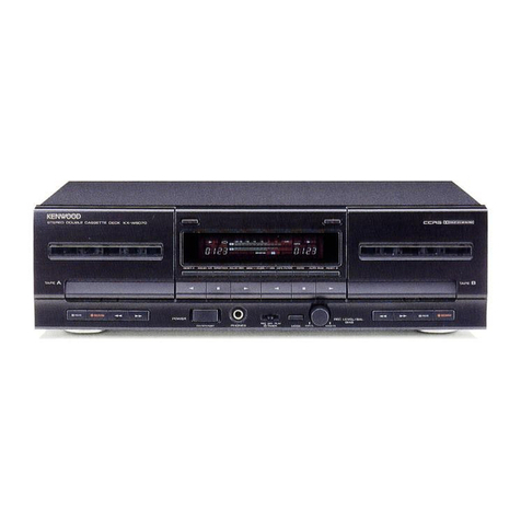
  9. Kenwood KX-58W User manual

Kenwood KX-58W User manual

|
STEREO
CASSETTE
TAPE
DECK
v
D
e
|
KŁ58W/s8GWw
|NENWOO
w
SERVICE
MANUAL
©1989-4
PRINTED
IN
JAPAN
B51-3792-00(T)2722
Knob
(POWER)
Cassette
lid*
Dressing
plate
*
Tape
counter
Cassette
lid*
Metallic
cabinet*
(K27-1965-04)
(A53-1098-03)
(B03-2571-04)
(B35-0036-05)
(A53-1099-03)
(A01-1739-01)
ENWOOD
sten
oouets
cas
perre
cece
kx-aaćw
»——
=>
Phone
jack
(3P)
Knob
(OPERATION)*
Slide
switch
Knob
(OPERATION)
*
Panel*
(E11-0162-05)
(K29-3582-03)
x
4
(S31-1017-05) (K29-3582-03)
x
6
(A20-5752-02)
:
Knob
(REC
BALANCE,
REC
LEVEL)
(K29-3591-04)
<=
1
>
ui
À
=
ed
L
N
GOD
o
Phono
jack
(4P)
AC
inlet*
(E13-0446-05)
(EO3-)
Foot
(J02-0161-04:Front)
x
2
(J02-0366-15:Rear)
x
2
<=
*Refer
to
Parts
List
on
page
35.
Photo
is
KX-58CW.
=
KX-58W/58CW
CONTENTS
D
AGCESSRIES
M
2
CONTROLS:
&
INDICATORS
nennen
sn
3
DISASSEMBLY
FOR
REPAAIR
2
4
BLOCK
&
LEVEL
DIAGRAM
nes
nei
5
CIRCUT
DESCRIPTION
unse
aa)
6
MECHANISM
DESCRIPTION
2.
12
ADJUSTMENT.
„use
19
REGLAGES
us
een
ea
Ri
ea
20
ABGEEJCH
aa
ies
et
ie
21
Accessories
Audio
cord
N
ADJUSTMENT/REGLAGES/ABGLEICH.........................
22
VOLTAGE
TABLES:
Zus.
22
P:C
BOARD
«rush
ten
OWA
lee
Ni
doco
23
SCHEMATIC
DIAGRAM........
eerie
A
29
EXPLODED
VIEW
(MECHANISM)...
33
EXPLODED:
VIEW
(UNIT)
iic
Rb
ets
34
PARTS:
LIST
MM
M
35
SPECIFICATIONS.
sde
ett
eren
Back
cover
KX-58W/58CW
CONTROLS
&
INDICATORS
PEAK
LEVEL
METER
|
DUBBING
keys
(>
NORMAL,
>>
HIGH)
These
keys
are
used
when
performing
:
tape-to-tape
dubbing.
r
CH
|
à
|
|
OFF
|
CS
|
|
OC
[oes
system]
EL
cl
KX-58W
DOLBY
NR
switch
COUNTER/RESET
key
This
key
is
used
to
reset
the
counter
to
“000”.
O—
DUBBING
—
o
m
O
ORECB
\
>
NORMAL
>
HIGH
RELAY
(A
»
B)
l50(8v
NR
REC
BALANCE
REC
LEVEL
Press
this
key
to
perform
relay
play.
|
|
CENTER
|
BOFFC
|
AEN
I
I
1
DOzoerscna]
|
Le
e
zen
sel
KX-58CW
REC
LEVEL
control
knob
This
knob
is
used
to
adjust
the
record.
ing
level.
‘
This
switch
is
used
to
select
the
Dolby
noise
reduction
among
‘’B’’,
''C''
and
“OFF”
positions.
(KX-58CW)
This
switch
is
used
to
turn
the
Dolby
noise
reduction
ON
and
OFF.
(KX-58W)
REC
BALANCE
control
knob
This
knob
is
used
to
adjust
the
balance
of
the
recording
level
between
L-
channel
and
R-channel.
POWER
switch
KENWOOD
STEREO
DOUBLE
CASSETTE
DECK
KX-5BCW
PEAK
LEVEL
METER
O—
DUBBING
—Q
co
orce
»
NORMAL
>
HIGH
RELAY
(A
>
B)
EEE
CENTER
a
5
6
8
or
c
nb
di
`
7.89
Q
DOLBY
NR
REC
BALANCE
REC
LEVEL
A
PLAY
BACK
DEEE)
Eject/Stop
(A/M)
key
When
the
deck
is
operating,
pressing
this
key
stops
operation,
and
pressing
it
again
opens
the
cassette
holder.
Fast
forward
(>>)
key
PHONES
jack
(KX-58CW
only)
Rewind
(<<)
key
Play
(>)
key
KX-58CW
am
II
PAUSE
PAUSE
(II)
key
Eject/Stop
(A/m)
key
Fast
forward
(>>)
key
Rewind
(<4)
key
Play
(>)
key
REC
key
|
KX-58W/58CW
-
DISASSEMBLY
FOR
REPAIR
*Take
out
the
case
beforehand.
1.
Remove
the
three
screws
@
and
undo
the
three
catches
©.
then
detach
the
dressing
panel.
2.
Press
the
EJECT
button,
then
detach
the
cassette
lid
©
from
the
cassette
holder.
3.
Detach
the
two
VR
knobs
@.
4.
Remove
the
two
screws
@
and
undo
the
two
catches
O,
then
put
out
the
sub
panel
towards
you.
5.
Disengage
the
tape
counter
belt
O.
6.
In
the
EJECT
mode,
remove
the
eight
screws
Q
installing
the
mechanism,
then
take
out
the
mechanism
in
the
direc-
tion
of
arrow
©.
7.
Undo
the
five
catches,
then
detach
the
switch
board
QD.
KX-58W/58CW
BLOCK
&
LEVEL
DIAGRAM
—
5.5dBs
—
9dBs
411mV
275mV
N
WO2-0693
nl
CUT
ooer
E
©)
LINE
out
LINE
(X)
MUTE
Po
10
IC
2
py
(KX-58W)
P.B
EQ.SW
LINE
NEA
DEMONE
O
-
72dBs
FILTER
HEAD
011,12
0.19mV
PHONE
DECK
B
EM
REC/P.B
#+>H
HEAD
=
REC
LEVEL
CONTROL
H
BUFFER
CIE
AMP
BALANCE
7
VR
IC
2
R/P
CONTROL
VR6,7
BIAS
REC
EQ.
Be
LEVEL
inr
AMP
`
VR9,IO
024
DECK
A
L3,4
07,8
(X)
:
SPEED
MECHANISM
VRS,6
MUTE
ADJ.
MOTOR
019
DECKB
BIAS
ERASE
ae
d
IC
3
A.B
MECHA
HEAD
IC8,
[—
dl
PLAY
SW
REC
EQ.SEL
y
com
Q20,21
BIAS
X)
BLAS
SW
E
B
MECHA
SELECTOR
022,83
REC.
SW
a
SPEED
MECHANISM
ADJ
MOTOR
Q23
VRIII2
KX-58W/58CW
CIRCUIT
DESCRIPTION
FUNCTION
OF
COMPONENTS
Recording/Playback
unit
(X28-1980-10-11)
Components
Use/Functions
Operation/Condition/Compatibility
C1
LA3246
Playback
EQ
IC
C2
uPC1330HA
Head
SW
IC
(Deck
B)
Controlled
by
pin
1
of
IC3.
Pin
4
becomes
5
V
in
recording
and
O
V
in
playback.
LM6416F-2227
Microprocessor
IC4
HA12136
Dolby
B
NR
IC
KX-58W
only.
uPC7818HF
+18
V
AVR
C6
M51951ASL
Reset
IC
CZ
M5218P-A
REC
EQ
amplifier
NF
constant
is
determined
by
IC8
and
IC9
to
ob-
NJM4565D
tain
the
recording
equalizer
property.
IC8,9
BA6251
EQ
selection
Pins
1-7
of
IC8
(IC9)
serve
to
control
the
respec-
tive
equalizer
devices:
IC10
TD62554S
REC
EO
selector
Controlled
by
029,
O16
and
Q17
to
control
IC8
and
IC9.
IC11
AN6888
Meter
IC
5-point
display
x2...
—10,
—6,
0,
+3,
+6
dB
IC12
M5218P-A
MPX
buffer
NJM4565D-D
01,2
2SC1740S
(Q,R)
Playback
EQ
output
SW
(Deck
B)
Controlled
by
Q15.
ON
when
deck
B
is
played
2SC945(A)
(O,P)
and
OFF
when
deck
A
is
played.
03,4
2SC1740S
(Q,R)
Playback
EQ
output
SW
(Deck
A)
Controlled
by
015.
ON
when
deck
A
is
played
2SC945(A)
(Q,P)
and
OFF
when
deck
B
is
played.
05,6
2SC1740S
(Q,R)
Playback
high-frequency
compensation
SW
Controlled
by
Q16.
Normally
ON.
OFF
only
in
2SC945(A)
(Q,P)
(Deck
A)
high-speed
dubbing
to
decrease
playback
high-
frequency
compensation
amount.
Q7,8
28C17408
(O,R)
REC
muting
Controlled
by
027.
ON
in
other
than
recording
to
2SC945(A)
(Q,P)
mute
the
recording
system
signal.
09,10
2SC2878(B)
Line
muting
Controlled
by
028.
ON
in
other
than
playback
to
mute
the
line
system
signal.
011,12
25C1845
(F,E)
Headphone
amplifier
Q13,14
2SC1740S
(Q,R)
Playback
EQ
120
4/70
u
SW
Controlled
by
Q15.
Q13
turns
ON
when
deck
A
is
2SC945(A)
(Q,P)
played
and
O14
turns
ON
when
deck
B
is
played.
Q15
28C17408
(Q,R)
Playback
EQ
120
4/70
y
inverter
Controlled
by
pin
9
of
IC3.
ON
when
deck
A
is
2SC945(A)
(Q,P)
played
and
OFF
when
deck
B
is
played.
Q16
2SC1740S
(Q,R)
Playback
EQ
inverter
ON
only
in
high-speed
dubbing.
Otherwise
OFF
2SC945(A)
(Q,P)
|
Q17
2SC1740S
(Q,R)
EQ
speed
inverter
Controlled
by
Q16.
OFF
in
normal
dubbing
and
2SC945(A)
(Q,P)
ON
in
high-speed
dubbing.
018
2SC2003
(L,K)
Dolby
IC
14
V
AVR
control
transistor
Converts
signal
system
18
V
into
Dolby
14
Y
Q19
2SD863
(E,F)
Bias
OSC
Oscillates
at
105
kHz.
020
2SC3246
Bias
current
METAL
SW
ON
in
recording
on
metal
tape
021
2SC3246
Bias
current
CrO?
SW
ON
in
recording
on
CrO2
or
metal
tape
022
2SC3246
Bias
SW
ON
in
recording
to
turn
ON
the
bias
oscillation
023
2SC1740S
(Q,R)
2SC945(A)
(Q,P)
Bias
SW
ON
soon
at
power
ON
Q24
2SC733(A)
(Q,P)
2SC933SC
(Q,R)
A
mechanism
speed
control
ON
in
high-speed
operation
€
KX-58W/58CW
CIRCUIT
DESCRIPTION
9
©
Components
Use/Functions
Operation/Condition/Compatibility
2SA733(A)
(Q,P)
2SAY33S(O,R)
REC
mut
Controlled
by
pin
3
of
IC3.
ON
in
other
than
recording.
2SA733(A)
(Q,P)
2SA933S(Q,R)
|
Line
mute
SW
Controlled
by
pin
4
of
IC3.
ON
in
other
than
playback.
2SA733(A)
(Q,P)
2SA933S(Q,R)
REC
mute
SW
Controlled
by
Q25.
ON
in
other
than
recording.
2SA733(A)
(Q,P)
2SA933S(Q,R)
Line
mute
SW
Controlled
by
Q26.
ON
in
other
than
playback.
2SC1740S(Q,R)
2SC945(A)
(0,P)
Tape
selector
SW
ON
with
metal
tape
loaded
on
deck
B
2SC3246
|
B
motor
SW
Controlled
by
pin
27
of
IC3.
In
case
of
relay
play,
OFF
until
the
end
of
the
tape
on
deck
A
is
reached,
and
ON
when
it
is
reached.
2SA733(A)
(0,P)
2SA933S(Q,R)
B
motor
control
ON
in
high-speed
operation
2SD863(E,F)
Microprocessor
5
V
AVR
Converts
12
V
for
mechanism
to
5
V
for
microprocessor.
25D822(0,P,E)
Components
Mechanism
12
V
AVR
Electric
circuit
module
(W02-0693-05)
Use/Function
Converts
to
12
V
for
mechanism
the
DC
obtained
by
halfwave
rectification
of
AC
IN.
Operation/Condition/Compatibility
HA12088ANT
DOLBY
B/C
noise
reduction
KX-58CW
only.
KX-58W/58CW
CIRCUIT
DESCRIPTION
MICROPROCESSOR
LM6416F-2227
1.
Operational
specification
The
KX-58W/58CW
is
a
mechanism
logic
double
deck
using
e
Relay
operation
two
mechanisms
made
by
GIKEN.
Its
circuit
control
is
per-
Relay
playback
(only
once)
from
deck
A
to
B
formed
by
a
microprocessor
by
use
of
inputs
from
mechan-
e
Timer
operation
ism
attached
switches
and
tact
switches.
Timer
playback:
decks
A
and
B
either
possible
Timer
recording:
deck
B
only
1-1
Functions
(1)
Features
(2)
Microprocessor
controlled
subjects
e
One
way
X2,
double
cassette
e
Selector
circuits
such
as
of
recording/playback,
deck
Deck
A:
playback
only
AIB,
etc.
Deck
B:
recording
and
playback
*
Dolby
IC
e
Dubbing
*
Bias
oscillation
circuit
Deck
A
to
B:
normal
speed
dubbing
e
LED
indication
Deck
A
to
B:
high
speed
dubbing
BRP
PDo
PC3
BIAS
PD:
2
PC2
BCPM
R.MUTE
PD2
3
PCI
KSO
L.MUTE
PD3
4
PCo
KSI
EXtal
5
PA3
KR
3
Xtal
6
Paz
KRZ
TEST
INT
7
PAI
KRI
RESET
RES
8
PAo
KRO
AHI
REo
9
Voo
D
ON
PE!
PGo
HISP
CHI
PE2
PFs
L.DUB
D
RP
PEs
PF2
LHDB
TEST
PFi
L
RLY
Vss
PFo
LREC
1-2
Pin
Functions
Pin
name
Designation
Description
PDo
BRP
B
REC/PLAY
selector
PD1
BIAS
B
BIAS
control
PD2
RMUT
B
REC
MUTE
control
PD3
LMUT
LINE
MUTE
control
EXtal
Xtal
Oscillator
INT
Test
mode
setting
:
Normal
RES
RESET
input
:
Normal
PEo
AIB
select
A
PE1
Dolby
ON/OFF
PE2
Dolby
B/C
PE3
Dolby
REC/PLAY
TEST
Connected
to
GND
(LSI
test
pin)
Vss
Connected
to
GND
KX-58W/58CW
CIRCUIT
DESCRIPTION
Pin
name
Designation
Description
PFo
LREC
REC
LED
:
ON
PF:
LRLY
Relay
LED
l
:
ON
LHDB
high
speed
dubbing
LED
: :
ON
LDUB
Normal
speed
dubbing
LED
: :
ON
HISP
Motor
speed,
EQ
speed
select
:
Normal
Connected
to
+5
V
Key
input
H:
without
input
L:
with
input
Key
scan
output
B
motor
ON/OFF
N.C.
(OPEN)
1-3
Keys
This
unit
turns
ON/OFF
by
the
mechanism
operation
because
of
using
mechanism
logics.
Its
circuit
control
is
performed
with
inputs
of
leaf
switches.
Name
Operation
PLAY
SW
(A
mechanism)
Decks
A/B:
A
selected
ON
when
head
of
A
mechanism
Line
mute
turns
ON
and
0.5
sec
later,
OFF.
ascends.
gnored
when
deck
B
is
in
recording
except
for
dubbing.
Decks
A/B:
B
selected
Line
mute
turns
ON
and,
in
case
of
during
play
of
deck
B,
OFF
0.5
sec
later.
gnored
when
deck
B
is
in
recording
except
for
dubbing.
B
main
motor
ON.
PLAY
SW
(B
mechanism)
(1)
Normally
ON
when
head
of
B
mechanism
ascends.
Decks
A/B:
B
selected
Line
mute
turns
ON,
and
0.5
sec
later,
OFF.
gnored
when
deck
A
is
in
play.
Decks
A/B:
A
selected
Line
mute
ON.
Ignored
when
deck
A
is
in
play.
(2)
For
recording
(not
dubbing)
Line
mute
and
recording
mute
turn
ON,
and
O.5
sec
later,
OFF.
At
OFF
Line
mute
and
recording
muter
ON.
Bias
OFF.
(3)
For
dubbing
Line
mute
and
recording
mute
turn
ON
and,
when
deck
A
is
in
play,
OFF
O.5
sec
later.
At
OFF
Recording
mute
ON.
Line
mute
ON
unless
deck
A
is
in
play.
Bias
OFF.
KX-58W/58CW
CIRCUIT
DESCRIPTION
Operation
(1)
Normally
At
ON
REC/PLAY:
REC
selected,
Decks
A/B:
B
selected
Bias
ON
and
REC
LED
ON.
Ignored
when
deck
A
is
in
play.
REC/PLAY:
PLAY
selected,
Decks
A/B:
A
selected
REC
LED
OFF.
Ignored
unless
REC
is
engaged.
REC
SW
(B
mechanism)
ON
when
REC
key
is
pressed
(with
cassette
hub)
(2)
For
dubbing
At
ON
REC/PLAY:
REC
selected,
Decks
A/B:
A
selected
Bias
ON
and
REC
LED
ON
REC/PLAY:
PLAY
selected.
REC
LED
OFF.
Effective
only
when
PLAY
SW
and
REC
SW
are
both
OFF.
Dubbing
LED
ON.
High
speed
dubbing
LED
and
relay
LED
OFF.
Effective
only
when
PLAY
SW
and
REC
SW
are
both
OFF.
High
speed
dubbing
LED
ON.
Dubbing
LED
and
relay
LED
OFF.
Effective
only
when
PLAY
SW
and
REC
SW
are
both
OFF.
Relay
LED
ON
and
B
motor
OFF.
High
speed
dubbing
LED
and
dubbing
LED
OFF
At
OFF
Dubbing
key
High
speed
dubbing
key
Relay
key
1-4
Operation
Key
handling
Operation
Press
the
dubbing
key.
Dubbing
LED
ON
Let
deck
A
play
and
set
PLAY
SW
Dubbing
(including
|
to
ON.
Decks
A/B:
A
selected
Line
mute
OFF
0.5
sec
later.
High-speed
mode)
Press
the
REC
key
of
deck
B,
and
set
the
REC
SW
and
PLAY
SW
to
ON.
REC/PLAY:
REC
selected.
Dolby
OFF.
Bias
ON.
Speed
is
high
for
high-speed
mode.
Line
mute
and
recording
mute
turn
ON
O.5
sec
later.
Dubbing
starts.
Press
the
relay
key.
Relay
LED
ON
and
B
mechanism
motor
OFF.
Let
deck
A
play
and
set
PLAY
SW
to
ON.
Decks
A/B:
A
selected.
Line
mute
OFF
0.5
sec
later.
B
mechanism
motor
OFF.
Relay
play
Press
the
PLAY
key
of
deck
B.
Although
the
PLAY
key
of
deck
B
is
locked,
since
the
motor
is
OFF,
the
head
does
not
ascend
and
the
PLAY
SW
of
deck
B
thus
remains
OFF.
Deck
A
stops
(as
tape
end
is
reached
or
an
operation
key
is
handled)
B
mechanism
motor
ON
and
thus
ON
PLAY
SW
of
deck
B.
Decks
A/B:
B
selected.
Line
mute
OFF
0.5
sec
later.
KX-58W/58CW
CIRCUIT
DESCRIPTION
1-5
Initial
status
1-6
Test
mode
A
test
mode
is
added
for
aiming
at
simplified
speed
ad-
Item
Status
justment.
BRP
PLAY
BIAS
OFF
(1)
Setting
method
-
Put
in
4
PIN
into
contact
with
GND
(momentarily).
REC
MUTE
ON
LINE
MUTE
ON
(2)
Contents
i)
When
the
test
mode
is
entered,
an
''H''
signal
is
output
Dolby
RIP
PLAY
to
pin
HISP.
Namely,
the
mechanism
is
set
to
the
high
speed
e
=
HISP
Normal
speed
mode.
S
BCPM
OFF
and
ON
3.5
sec
later.
ii)
Each
time
the
high
speed
dubbing
key
is
pressed,
pin
HISP
>
is
inverted.
as
All
OFF
(3)
Canceling
method
(Make
pin
4
open.
That
pin
4
remains
in
contact
with
GND
is
inadvisable.)
i)
Press
the
dubbing
key
or
the
relay
key.
ii)
Perform
recording.
Needless
to
say,
the
test
mode
will
also
be
canceled
by
pow-
er
OFF.
1-7
Timing
chart
(D
STOP>PLAY
STOP
(A)
A
L.MUTE
|
0.5
s
1
T
|
|
|
|
I
A
PLAY
SW
ON
A
PLAY
SW
OFF...
earlier
ap-
prox.
tens
of
usec
with
line
mute
ON
(2)
STOP
REC
-
STOP
(B)
AHI
BRP
E
EM
PR
nn,
BULL
Qu.
af
vU
I
mur
ue.
00
To
70
|
0.5
s
LMUT
Zu
ae
O
à
coal
I
DRP
I
HISP
PLAY
SW
and
Ces
:
:
REC
SW,
OFF
only
in
dubbing
PLAYS
EN
(almost
the
same
HISP:
only
in
high
REC
SVV
ON
time)
E
speed
dubbing
3
11
J
KX-58W/58CW
MECHANISM
DESCRIPTION
1.
Function
Description
of
Main
Parts
(Fig.
1
—
3)
1-1.
1-2.
1-3.
1-4.
1-5.
ASSIST
GEAR
(36)
[for
playback]:
This
is
driven
by
the
TRIGGER
ARM
(II)
(26)
and
swings
the
SHIFT
ARM
(29).
SHIFT
ARM
(29)
[for
playback]:
This
is
swung
by
the
cam
of
the
ASSIST
GEAR
(36)
and
moves
up
the
HEAD
BASE
(89)
via
SPRING
(72).
PLAY
ARM
(30)
[for
palyback]:
Control
is
made
by
the
BOSS
of
the
HEAD
BASE
(89).
The
TAKEUP
REEL
ASS'Y
is
operated
by
the
PLAY
GEAR
(34)
on
the
PLAY
ARM
(30).
CLUTCH
ASS'Y
(42)
[for
transmission
of
rotation
in
the
Play,
FF,
REW
mode]:
This
transmits
the
rotation
from
the
flywheel
to
both
left
and
right
reels
via
clutch
for
fast-
forward
and
rewind.
TRIGGER
ARM
(II)
(26)
[for
playback]:
This
is
swung
by
the
PLAY
LEVER
(16)
via
TRIGGER
ARM
(I)
(24),
and
riggers
the
ASSIST
GEAR
(36).
+
2.
Stop
Status
(Fig.
1),
(Fig.
3)
221;
2-2.
12
(89)
HEAD
BASE
The
SHIFT
ARM
(29)
is
energized
by
the
SPRING
(77).
The
cam
of
the
ASSIST
GEAR
(36)
comes
contact
with
the
edge
of
the
SHIFT
ARM
(29).
(34)
PLAY
GEAR
N
(77)
SPRING
(29)
SHIFT
ARM
Fig.
1
1-6.
1-9.
2-3.
2-4.
LOCK
CAM
LEVER
(II)
(23)
[for
ejecting]:
This
prevents
the
EJECT
LEVER
(22)
from
shifting
during
stop
opera-
tion,
and
it
also
inhibits
the
auto
stop
operation
in
the
stop
mode.
LOCK
CAM
LEVER
(1)
(20)
[for
locking
of
operation
lever]
TRIGGER
ARM
(27)
[for
auto
stop]:
During
the
auto
stop
operation,
this
is
swung
by
the
power
transmitted
from
the
flywheel
via
the
AUTO
PULLEY
(38)
and
AUTO
GEAR
(33),
and
slides
the
LOCK
CAM
LEVER
(I)
(20).
AUTO
SENSOR
(21)
[for
auto
stop]:
This
is
swung
by
the
T
REEL
ASS'Y
(8)
and
locks
the
AUTO
CAM
(32)
when
the
rotation
stops.
.
PAUSE
LOCK
ARM
(14)
[for
auto
stop]:
This
inhibits
the
auto
stop
operation
in
the
pause
mode.
.
AUTO
LOCK
ARM
(28)
[for
auto
stop]:
This
inhibits
the
auto
stop
operation
during
the
stop
or
pause
mode.
The
TRIGGER
ARM
(II)
(26)
is
energized
by
the
SPRING
(74).
The
cam
located
on
the
rear
of
the
ASSIST
GEAR
(36)
comes
contact
with
the
boss
at
the
edge
of
the
TRIG-
GER
ARM
(II)
(26)
so
that
the
rotation
of
the
GEAR
(36)
is
locked.
(42)
CLUTCH
ASS'Y
(30)
PLAY
ARM
(36)
ASSIST
GEAR
PAUSE
STOP
Parts
Discription
(Front
perspective
view)
KX-58W/58CW
2
MECHANISM
DESCRIPTION
-—
(8)
(42)
E
REEL
DISK
CLUTCH
ASS'Y ASS'Y
MOTOR
(39)
DRIVE
BELT
(41)
(38)
F.R.
BELT
AUTO
PULLY
(7)
FLYWHEEL
ASS'Y
(40)
AUTO
BELT
(36)
——
_
ASSIST
GEAR
xa
Fig.
2
Discription
of
power
transmission
(32)
~
AUTO
CAM
(42)
|
CLUTCH
ASS'Y
(33)
AUTO
GEAR
(27)
TRIGGER
ARM
(26)
TRIGGER
ARM
(II)
ati,
(14)
(74)
PAUSE
LOCK
ARM
TRIGGER
ARM
SPRING
(28)
AUTO
LOCK
ARM
(31)
PAUSE
CAM
(23)
LOCK
CAM
LEVER
(II)
(20)
LOCK
CAM
LEVER
(I)
PAUSE
STOP
FF
REW
24)
|
PLAY
REC
TRIGGER
ARM
(I)
Fig.
3
Parts
Discription
(Rear
perspective
view)
KX-58W/58CW
MECHANISM
DESCRIPTION
3.
FF
(Fast-Forward)
Operation
(Fig.
4)
3-1.
The
CLUTCH
ASS'Y
(42)
is
stretched
in
the
direction
of
c»
(@)
by
the
resultant
of
the
SPRING
(71)
and
the
FR
BELT
(41).
3-2.
In
the
stop
mode,
the
CLUTCH
ASS'Y
(42)
stops
at
the
neutral
position
by
the
lug
(or
pro-
trusion)
(@)
of
the
FF
LEVER
(18).
3-3.
When
the
FF
LEVER
is
pressed
and
locked,
the
CLUTCH
ASS'Y
(42)
falls
down
into
the
concave
section
(@)
of
(18).
3-4.
The
gear
of
the
CLUTCH
ASS'Y
(42)
is
engag-
ed
with
the
FF
GEAR
(34).
3-5.
The
rotation
of
the
FLYWHEEL
(7)
is
transmit-
ted
to
the
T
REEL
ASS'Y
(8)
via
the
CLUTCH
ASS'Y
(42)
and
the
FF
GEAR
(34).
Fig.
4
F.F.
4.
Rewind
(REW)
Operation
(Fig.
5)
4-1.
The
CLUTCH
ASS'Y
(42)
is
streched
in
the
direction
of
c»
(@)
by
the
resultant
of
the
SPRING
(71)
and
the
FR
BELT
(41).
(Fig.
4)
4-2.
In
the
stop
mode,
the
CLUTCH
ASS'Y
(42)
stops
at
the
neutral
position
by
the
lug
(or
pro-
trusion)
(@)
of
the
FF
LEVER
(18).
(Fig.
4)
4-3.
When
the
REW
LEVER
(17)
is
pressed
and
locked,
the
CLUTCH
ASS'Y
(42)
is
rotated
in
the
direction
of
(@)
against
the
force
of
SPR-
ING
(71)
due
to
slope
(@).
4-4.
The
gear
of
the
CLUTCH
ASS'Y
(42)
is
engag-
ed
with
the
gear
of
the
S
REEL
ASS'Y
(9).
4-5.
The
rotation
of
the
FLYWHEEL
(7)
is
transmit-
ted
to
the
S
REEL
ASS'Y
(9)
via
the
CLUTCH
ASS'Y
(42).
REWING
Fig.
5
REW
14
KX-58W/58CW
MECHANISM
DESCRIPTION
5.
Play
Operation
(Fig.
6)
5-1.
5-2.
5-3,
5-4.
5-5,
5-6.
5-7.
5-8.
59.
Press
the
PLAY
LEVER
(16)
(
9
@).
The
TRIGGER
ARM
(I)
(24)
which
is
fixed
on
the
PLAY
LEVER
(16)
with
the
screw
is
also
moved
in
the
direc-
tion
of
=
6.
The
notch
(($)
of
the
TRIGGER
ARM
(I)
(24)
comes
contact
with
the
TRIGGER
ARM
(M
(26).
(
m
@.)
At
the
same
time,
the
notch
(@)
of
the
TRIGGER
ARM
(I)
(24)
comes
in
touch
with
the
notch
(©)
of
the
FF
and
REW
LEVERS
(18),(17).
(
sp
©.)
The
TRIGGER
ARM
(I)
(24)
swings
in
the
direction
of
=)
©
using
(O),
(©)
as
supporting
points
and
(@),
(©)
as
application
points.
The
TRIGGER
ARM
(II)
(26)
is
swung
in
the
direction
of
=
©
by
notch
(($)
of
the
TRIGGER
ARM
(I)
(24).
The
edge
(@)
of
the
TRIGGER
ARM
(II)
(26)
is
unlock-
ed
from
the
section
(@)
of
the
ASSIST
GEAR
(36).
Since
the
cam
(($)
of
the
ASSIST
GEAR
(36)
is
pushed
by
the
protrusion
(@)
of
the
SHIFT
ARM
(29),
the
ASSIST
GEAR
(36)
is
rotated
in
the
direction
of
C»
O.
When
rotated
a
bit,
the
gear
section
of
the
ASSIST
GEAR
(36)
is
engaged
with
the
gear
of
the
FLYWHEEL
(7)
and
then
it
is
continued.
By
the
cam
(($)
of
the
ASSIST
GEAR
(36),
the
SHIFT
ARM
(29)
is
lifted
against
the
SPRING
(77),
then
the
hook
((8)
on
the
edge
of
it
is
swung
in
the
direction
of
+
O.
Fig.
6
Play
(Unlock
ASSIST
GEAR)
STATUS
OF
STOP
Fig.
7
Play
(Rotate
ASSIST
GEAR)
KX-58W/58CW
MECHANISM
DESCRIPTION
5-10.
The
HEAD
BASE
(89)
is
slid
on
the
surface
of
the
chas-
sis.
The
hook
of
the
HEAD
BASE
(89)
and
that
of
the
SHIFT
ARM
(29)
are
connected
with
the
SPRING
(72).
5-11.
When
the
SHIFT
ARM
(29)
is
lifted,
the
HEAD
BASE
(89)
is
also
moved
up
and
comes
in
contact
with
the
notch
(Q),
so
that
the
unit
(cassette
deck)
is
entered
the
play
mode.
5-12.
In
the
play
mode,
due
to
the
rise
of
the
HEAD
BASE
(89),
the
PLAY
ARM
(30)
is
swung
in
the
direction
of
=)
Q
(by
the
SPRING
(76))
and
further
pushed
up
by
the
BOSS
(Sof
the
HEAD
BASE
(89).
5-13.
When
the
HEAD
BASE
(89)
reaches
the
play
position,
the
PLAY
GEAR
(34)
is
engaged
with
the
CLUTCH
ASS'Y
(42)
and
the
T
REEL
ASS'Y
(8)
to
transmit
the
rotation.
5-14.
The
ASSIST
GEAR
(36)
still
rotates
even
after
the
HEAD
BASE
(89)
stops
and
stops
when
the
boss
(O)
of
the
TRIGGER
ARM
(II)
(26)
comes
in
contact
with
the
stopper
(($)
of
the
ASSIST
GEAR
(36).
(See
Fig
9.)
5-15.
During
the
PLAY
LEVER
(16)
is
locked,
the
TRIGGER
ARM
(ID
(26)
is
held
at
the
position
shown
in
the
figure
(Fig.
9)
by
the
TRIGGER
ARM
(I)
(24).
(See
Fig.
6.)
5-16.
When
the
PLAY
LEVER
(16)
is
released,
the
TRIGGER
ARM
(I)
(24)
becomes
free
and
the
TRIGGER
ARM
(ID
(26)
is
swung
by
the
SPRING
(74),
and
the
ASSIST
GEAR
(36)
is
also
unlocked.
(See
Fig.
9,
Fig.
10.)
5-17.
The
ASSIST
GEAR
(36)
is
rotated
in
the
direction
of
c»
©
by
the
pressure
of
the
SHIFT
ARM
(29),
and
stops
when
the
boss
(Q)
at
the
edge
of
the
TRIGGER
ARM
(ID
(26)
comes
in
contact
with
the
(@)
portion
of
the
cam.
(See
Fig.
10.)
16
=
(34)
ke
Om
I
(42)
‘
ligi
7
R
|
(89)
=
Gd
a
SD
X
M
|
A
i
6
Jo
Le
(7)
+
cé
b
sl
Je",
T
ae
(36)
Fig.
8
Play
(move
up
HEAD
BASE)
Fig.
10
Play
(Release
play
mode)
KX-58W/58CW
MECHANISM
DESCRIPTION
6.
Auto
Stop
Operation
(See
Fig.
11)
6-1.
6-2.
6-3.
6-4.
DURING
PLAY
Fig.
11
6-8.
6-9.
6-11.
The
AUTO
CAM
(32)
is
rotated
by
the
FLYWHEEL
(7)
via
AUTO
PULLEY
(38)
and
AUTO
GEAR
(33)
in
the
direction
of
c»
@.
The
AUTO
SENSOR
LEVER
(21)
comes
contact
with
the
bottom
of
the
T
REEL
ASS'Y
(8)
through
the
REEL
WASHER
(109),
SPRING
(66)
and
the
T
REEL
SLIDER
(108).
In
the
play
mode,
the
boss
(
(Y)
at
the
edge
of
the
AUTO
SENSOR
LEVER
(21)
is
swung
in
the
direction
of
=)
©
by
the
rotation
of
the
T
REEL
ASS'Y
(8).
Since
the
boss
(@)
of
the
AUTO
SENSOR
LEVER
(21)
moves
around
the
inner
edge
of
the
AUTO
CAM
(32),
it
is
not
engaged
with
the
protrusion
(GS).
6-5.
6-6.
6-7.
EM
Auto
stop
(Play
—
Auto
Stop)
In
the
stop
mode,
the
end
section
(@)
of
the
AUTO
LOCK
ARM
(28)
comes
contact
with
the
notch
of
the
LOCK
CAM
LEVER
(ID
(23).
The
boss
(©)
of
the
AUTO
SENSOR
LEVER
(21)
is
pushed
in
the
direction
of
=
@
by
the
SPRING
(75)
installed
on
the
AUTO
LOCK
ARM
(28).
.Since
the
boss
of
the
AUTO
SENSOR
LEVER
(21)
comes
contact
with
the
inner
edge
of:the
AUTO
CAM
(32)
in
the
same
way
as
when
the
T
REEL
ASS'Y
(8)
is
rotated,
the
auto
stop
operation
does
not
function.
In
the
pause
mode,
the
PAUSE
LOCK
ARM
(14)
is
swung
by
pressing
with
the
PAUSE
LEVER
(11),
and
the
other
end
of
it
make
the
AUTO
SENSOR
LEVER
(21)
swing
in
the
direction
of
sp
Q
.
In
the
same
way
as
the
stop
mode,
the
auto
stop
opera-
tion
does
not
function.
When
the
T
REEL
ASS'Y
(8)
stops
rotating,
the
boss
(@)
of
the
AUTO
SENSOR
LEVER
(21)
is
moved
to
the
center
of
the
AUTO
CAM
(32)
by
the
bank
section
(@)
of
the
AUTO
CAM
(32)
and
is
engaged
with
the
protrusion
(Qi.
The
BOSS
@of
the
AUTO
SENSOR
LEVER
(21)
is
locked
with
the
PROTRUSION
(3
of
the
AUTO
CAM
(32).
In
this
situation,
the
AUTO
PULLEY
(38)
continues
rota-
tion
in
the
direction
of
Mb
@so
that
the
AUTO
CAM
(32)
is
moved
in
the
direction
of
sj
@
with
the
point
@
of
the
AUTO
GEAR
(33)
as
the
point
of
support.
The
end
of
the
AUTO
ARM
(27)
is
moved
in
the
direc-
tion
of
Mb
©
and
moves
the
LOCK
CAM
LEVER
(20)
to
release
it.
(See
Fig.
12.)
(75)
Fig.
12
Auto
stop
(During
STOP
&
PAUSE)
17
KX-58W/58CW
MECHANISM
DESCRIPTION
7.
Rec
Operation
(See
Fig.
13)
(16)
7-1.
The
REC
SENSOR
ARM
(15)
is
swung
in
the
direction
of
mp
@
(when
the
recordable
cassette
is
loaded).
7-2.
Press
the
REC
LEVER
(10)
in
the
direction
of
m
©
By
this
operation,the
REC
switch
(S3)
is
turned
ON.
7-3.
At
this
time,
the
PLAY
LEVER
(16)
is
pushed
by
the
shoulder
of
the
REC
LEVER
(10),
so,
the
unit
enters
the
play
mode
from
the
view
point
of
mechanism.
Fig.
13
Rec
Operation
8.
Pause
Operation
(See
Fig.
14)
8-1.
When
the
PAUSE
LEVER
(11)
is
pressed
(in
the
direc-
tion
of
m
@),
notches
@
and
®
press
the
ends
of
the
PINCH
ROLLER
ASS'Y
(37)
and
the
PLAY
ARM
ASS'Y
(30)
to
swing
them
respectively
(in
the
direction
ot
+
E
©)
8-2.
The
PINCH
ROLLER
ASS'Y
(30)
is
released
from
the
CAPSTAN
(7)
and
the
PLAY
GEAR
(34)
is
released
from
the
CLUTCH
ASS'Y
(42)
so
that
the
unit
enters
the
pause
mode.
Fig.
14
Pause
Operation
18
KX-58W/58CW
P
ADJUSTMENT
m,
INPUT
OUTPUT
CASSETTE
TAPE
ALIGNMENT
CASSETTE
DECK
SECTION
TAPE:
NORMAL,
DOLBY:
OFF,
INPUT:
LINE
0dBs=0.775V
]
REC/PLAY
HEAD
POWER:
OFF
Demagnetize
the
REC/PLAY
DEMAGNETIZATION
Remove
the
REC/PLAY
head
with
a
head
R
cassette
door.
head
demagnetizer.
REC/PLAY
Clean
the
REC/PLAY
head
head
erase
head,
capstan
and
CLEANING
erase
head,
pinch
roller
using
a
cotton
capstan,
swab
slightly
damped
pinch
roller.
with
alcohol.
Azimuth
AZIMUTH
MTT-114,
TCC-153
adjustment
Maximum
output,
10kHz,-10dB
screw
*
The
Test
mode
is
Adjust
the
tape
speed
so
—
TAPE
SPEED
MTT-111,
TCC-110
initiated
when
TP4
that
a
6kHz
signal
is
(HI
SPEED)
3kHz
(TEST)
is
connected
produced
at
the
center
-4dB
momentarily
to
the
of
the
tape.
GND.
PLAY
|
%
In
the
Test
mode
Adjust
the
tape
speed
so
TAPE
SPEED
MTT-111,
TCC-110
condition,press
th
that
a
3kHz
signal
is
(NORMAL)
3kHz
HIGH
DUBBING
Key.
produced
at
the
center
-4dB PLAY
of
the
tape.
MTT-150
400Hz(200nWb)
VR3CL)
Output
level:
-6.0dBs
PLAYBACK
MTT-256
VR4(R)
a
LEVEL
315Hz
160nWb)
YR1CL)
Output
level:
-9.0dBs
MTT-256U,
TCC-160
VR2CR)
315Hz
(220nWb)
Output
level:
-5,0dBs
Adjust
REC
LEVEL
s
(hat
the
REC
monito
Record
1kHz
and
10kHz
in
output
becomes
alternation
and
adjust
the
(A)
-29dBs
at
1kHz,
VR5
CL)
variable
resistors
which
BIAS
CURRENT
1kHz,
-30dBs
then
record
and VR6
CR)
control
the
bias
current
10kHz,
-30dBs
reproduce
signal
so
that
the
same
playback
of
1kHz
and
10kHz
level
is
obtained.
in
alternation.
a.
Record
and
reproduce
a
lkliz
Adjust
the
variable
RECORD
LEVEL
(A)
signal
under
the
resistors
so
that
a
1kHz,-10dBs
conditions
set
playback
level
of
-9dBs
in
«4».
is
obtained.
X
The
tape
speed
in
the
Test
mode
is
switched
alternately
to
NORMAL/HIGH
SPEED
by
means
of
the
NORMAL
DUBBING
key.
To
cancel,
press
the
NORMAL
DUBBING
key
or
RELAY
key.
PN
mm.
KX-58W/58CW
REGLAGES
REGLAGE
DE
REGLAGE
DE
|
REGLAGE
DU
MAGNETO
MONET
P
ITEM
L'
ENTREE
L'
ALIGNEMENT
ALIGNER
POUR
Demagnétiser
la
téte
POWER:
OFF
Tête
D'
ENREGISTREMENT/LECTURE
DEMAGNETISATION
Eloigner
la
porte.
|
D'
ENREGISTREMENT/
avec
un
démagnétiseur
LECTURE
de
téte.
Téte
Nettoyer
la
téte
D'
ENREGISTREMENT/
D'
ENREGISTREMENT/LECTURE
LECTURE
téte
la
tête
d
effacement,
le
NETTOYAGE
d'
effacenent,
cabestan
et
le
galetpresseur
cabestan,
avec
un
coton-tige
galetpresseur.
légèrement
imbibé
d'alcool
AZIMUT
MTT-114,
TCC-153
Vis
d'azimut
Sortie
maximer.
10kHz.-10dB
AQUE
IMPRIMEE
CX28-198X-XX)
Le
mode
de
test
est
Régler
la
vitesse
de
bande
VITESSE
DE
MTT-111,
TCC-110
initialisé
quand
TP4
de
façon
qu
un
signal
DEF
ILEMENT
3kHz
(test)
est
raccordé
de
6kHz
soit
produit
au
CHI
SPEED)
-AdB
momentanément
à
GND.
centre
de
la
bande.
PLAY
*
En
condition
de
Régler
la
vitesse
de
bande
VITESSE
DE
MTT-111,
TCC-110
mode
de
test,
pre
de
facon
qu'un
signal
DEF
ILEMENT
3kHz
sser
la
touche
HIGH
de
3kliz
soit
produit
au
CNORMAL)
-4dB
DUBBING.
PLAY
centre
de
la
bande.
MTT-150
400Hz
(200nWb)
VR3(G)
Niveau
de
sortie:
-6,0dBs
NIVEAU
DE
MTT-256
VR4(D)
LECTURE
315Hz(160nWb)
)
VR1(G)
Niveau
de
sortie:
-9,0dBs
MTT-256U,
TCC-16
VR2(D)
315Hz(220nWb)
Niveau
de
sortie:
-5,0dBs
Régler
REC
LEVEL
d
façon
que
la
sortie
de
moniteur
Enregistrer
un
signal
de
REC
soit
de
-29dBs
(lz
et
10kHz
en
alternance
COURANT
DE
(A)
a
lkHz,
puis
en
VR5
(G)
et
ajuster
les
rósistances
POLARISATION
1RHz.
-30dBs
registrer
et
VR6
(D)
variables
qui
commandent
le
10kHz.-30dBs
reproduire
des
courant
de
polarité
de
signaux
de
1kHz
et
façon
à
obtenir
le
même
10kHz
en
niveau
de
lecture.
alternance.
Enregistrer
et
reproduire
un
Ajuster
les
résistances
NIVEAU
(A)
signal
de
1kHz
variables
de
facon
á
D'
ENREGISTREMENT
1kHz.-10dBs
dans
les
obtenir
un
niveau
de
conditions
lecture
de
-8dBs.
précisées
en
445.
%
La
vitesse
de
la
bande
en
mode
de
test
est
alternativement
commutée
sur
NORMAL/HIGH
SPEED
par
la
touche
HIGH
DUBBING.
Pour
annuler,
presser
la
touche NORMAL
DUBBING
ou
RELAY.
20

This manual suits for next models

1

Other Kenwood Tape Deck manuals

Kenwood 101CT Operating instructions

Kenwood

Kenwood 101CT Operating instructions

Kenwood 101CT User manual

Kenwood

Kenwood 101CT User manual

Kenwood CT-405 User manual

Kenwood

Kenwood CT-405 User manual

Kenwood KX-94W User manual

Kenwood

Kenwood KX-94W User manual

Kenwood DX-7030 User manual

Kenwood

Kenwood DX-7030 User manual

Kenwood KX-W595 User manual

Kenwood

Kenwood KX-W595 User manual

Kenwood KX-W1060 User manual

Kenwood

Kenwood KX-W1060 User manual

Kenwood X-7WX User manual

Kenwood

Kenwood X-7WX User manual

Kenwood KX-W4040 User manual

Kenwood

Kenwood KX-W4040 User manual

Kenwood CT-203 User manual

Kenwood

Kenwood CT-203 User manual

Kenwood KX-W595 User manual

Kenwood

Kenwood KX-W595 User manual

Kenwood KX-W5040 User manual

Kenwood

Kenwood KX-W5040 User manual

Kenwood KX-620 User manual

Kenwood

Kenwood KX-620 User manual

Kenwood 1050CT User manual

Kenwood

Kenwood 1050CT User manual

Kenwood KX-W8040 User manual

Kenwood

Kenwood KX-W8040 User manual

Kenwood KX-W8040 User manual

Kenwood

Kenwood KX-W8040 User manual

Kenwood CT-203 User manual

Kenwood

Kenwood CT-203 User manual

Kenwood CT-201 User manual

Kenwood

Kenwood CT-201 User manual

Kenwood KXF-W1030 User manual

Kenwood

Kenwood KXF-W1030 User manual

Kenwood KX-7030 User manual

Kenwood

Kenwood KX-7030 User manual

Kenwood KX-W895 User manual

Kenwood

Kenwood KX-W895 User manual

Kenwood KX-W8050 User manual

Kenwood

Kenwood KX-W8050 User manual

Kenwood CT-405 User manual

Kenwood

Kenwood CT-405 User manual

Kenwood KX-97CW User manual

Kenwood

Kenwood KX-97CW User manual
Popular Tape Deck manuals by other brands

Onkyo TA-2047 Service manual

Onkyo

Onkyo TA-2047 Service manual

Technics RS-M27OX operating instructions

Technics

Technics RS-M27OX operating instructions

STUDER REVOX A700 Service manual

STUDER REVOX

STUDER REVOX A700 Service manual

Akai 1730-SS Service manual

Akai

Akai 1730-SS Service manual

Onkyo TA-2130 Service manual

Onkyo

Onkyo TA-2130 Service manual

Advent 201 Service manual

Advent

Advent 201 Service manual

Telefunken M 204 E Service information

Telefunken

Telefunken M 204 E Service information

Pioneer RT-909 operating instructions

Pioneer

Pioneer RT-909 operating instructions

Onkyo TA-RW909 instruction manual

Onkyo

Onkyo TA-RW909 instruction manual

Harman Kardon HK705 owner's manual

Harman Kardon

Harman Kardon HK705 owner's manual

Pioneer CT-8R Service manual

Pioneer

Pioneer CT-8R Service manual

Panasonic sv-3200 operating instructions

Panasonic

Panasonic sv-3200 operating instructions

Pioneer CT-740 operating instructions

Pioneer

Pioneer CT-740 operating instructions

Sanyo RD5035 Service manual

Sanyo

Sanyo RD5035 Service manual

Interpack ET xtreme Series Operations manual & parts list

Interpack

Interpack ET xtreme Series Operations manual & parts list

Rotel RD-965BX owner's manual

Rotel

Rotel RD-965BX owner's manual

Sony DTC-A8 Service manual

Sony

Sony DTC-A8 Service manual

Technics SV-DA10 operating instructions

Technics

Technics SV-DA10 operating instructions

manuals.online logo
manuals.online logoBrands
  • About & Mission
  • Contact us
  • Privacy Policy
  • Terms and Conditions

Copyright 2025 Manuals.Online. All Rights Reserved.