Activeforever Fluid Cycle XT E720 User manual

2
Contents
1. Contents of E720 Box.
2. E720 assembly instructions.
3. Tank filling and water treatment.
4. Long term water treatment and basic
operation.
5. E720 Control arm.
6. Maintenance.
7. Troubleshooting guide
8. The E720 Ergometer with USB Function
9. Tank belt drive adjustment.
10. Parts list and Warranty.
As with any piece of fitness equipment,
consult a physician before beginning
your E720 exercise program.
CAUTION
Use two hands and follow all safety in-
structions whenever raising or lowering
the E720 control arm.
Warning
Do not remove feet or hands while
crank is in motion. The crank will con-
tinue to rotate and could cause injury.
Training with E720

3
Box Contents
1x Upper seat frame
1x Main frame
1x Upper/Lower seat
frame
1x Right crank
pedal
1x L-pin
1x Fill funnel/hose
3x Leveler
Hex Keys 2x Batteries
3x Frame bolts 8x Seat bolts
7x Frame bolt washers
8x Seat bolt
washers
3x Main frame
Nylock nut 1x Multi-tool
M10 Plastic
Washer
Owners Manual
Seat frame lubricat-
ing grease
1x Lower seat frame
Chlorine Tablets x 4

4
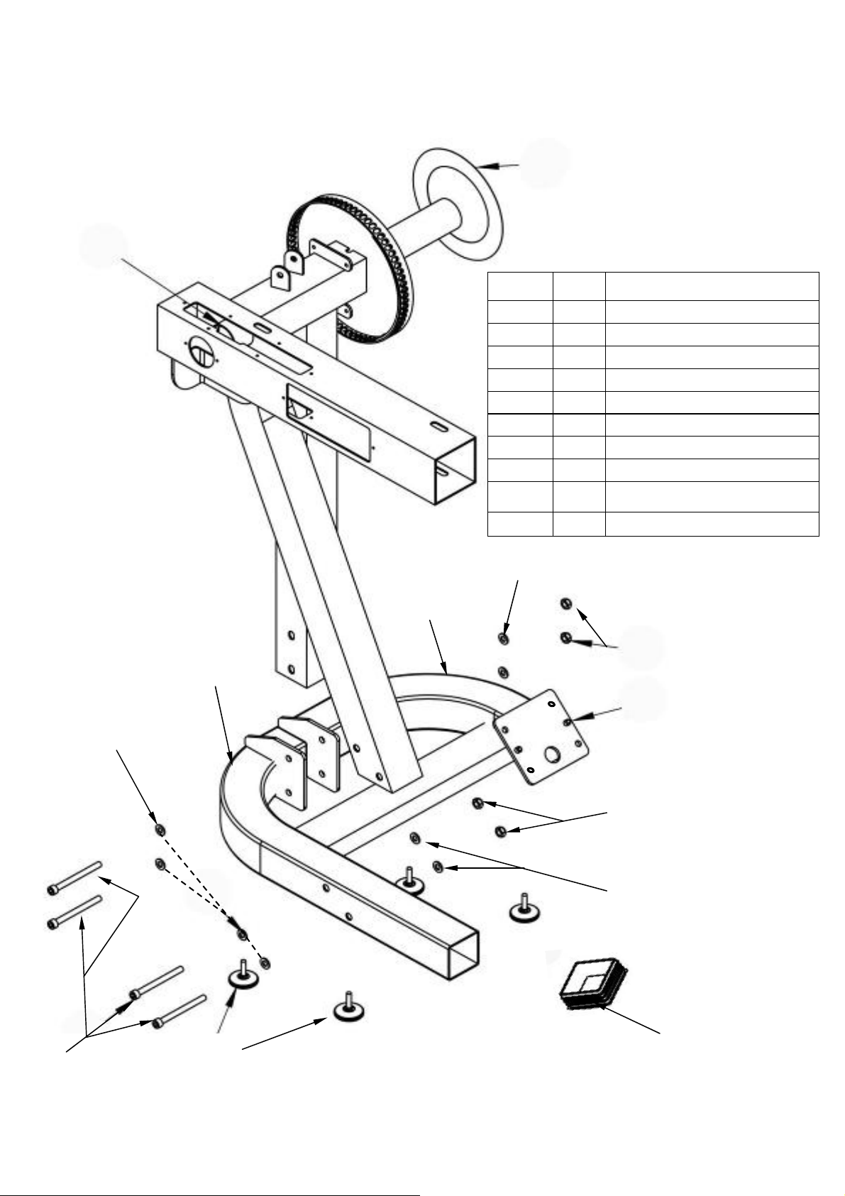
E720 Assembly Instructions
Upper seat
Lower seat
Step 1: Attach upper seat to
upper seat frame using 4x
M6x20mm bolts and 4x
16x6xl washers. Step 2: Attach lower seat
to upper seat frame using
4x M6x20mm bolts and 4x
16x6xl washers.
Upper seat frame
M6x20mm bolt
M6x16x1 washer
M6x16x1 washer
M6x20mm bolt

5
Step 3: Attach lower seat
to lower mainframe using
4x M10x25mm bolts, 4x
M10 Nylock nuts and 8x
21x11x2 washers
M10 Nylock nut
21x11x2 washer
M10x25mm bolt
E720 Assembly Instructions

6
L-Pin
M10x25mm
bolt
M10 Nylock
nut
21x11x2 washer
Step 4: Lower upper seat frame onto lower mainframe and secure using
1x M10x25mm bolt, 1x M10 Nylock nut, 3x 21x11x2 washers and L-pin.
Note: Tighten the M10x25mm bolt, washers and Nylock until lightly snug
only. Over-tightening will prevent the seat from rotating. Use the L-pin to
tighten the upper seat frame once rotated into place.
E720 Assembly Instructions
M10 plastic
washer
Before installing the upper seat frame onto the
lower, use the supplied grease and apply liberally
between the two sliding surfaces

7
Step 5: Secure right pedal onto Crank arm. The pedal threads have a blue
coating which will feel very tight when threaded onto the crank arm. This is a
type of thread locker, and once in contact with the crank arm threads will acti-
vate in approximately 15minutes.
Caution! Extreme over-tightening could damage the aluminum threads on the
crank arm.
Note: Allow 15 minutes for the thread-locker to activate before first time use.
Check pedal tightness on a regular basis and tighten as needed with a 15mm wrench.
E720 Assembly Instructions

8
Tank Filling and Water Treatment
Yellow
Tank
Plug
Filling hose and
funnel
Note: A large bucket is required for filling (Not included).
In areas where tap water quality is known to be poor, FDF recommends the use of distilled water.
Open the tank plug and insert hose
into tank (rotating the impeller
slightly may be necessary to allow
the hose to pass), move the tank
adjuster handle to level 20 and be-
gin filling. Do not fill the tank
higher than the level indicator on
the front of the clear shell. A prop-
erly filled tank holds approximately
8 liters of water.
Do not under any circumstances
put fingers into the tank. Use the
end of the hose to move the impel-
ler should the need arise.
WARNING
Note: Lower tank plug is permanently
sealed.
Water Treatment Procedures:
1. Add Chlorine tablet.
2. Enough Chlorine Tablets are supplied
for many years of Water treatment.
Add a chlorine Tablet whenever the
Water appears dirty or cloudy.
WARNING: Only use First Degree
Fitness Supplied Water treatment tab-
lets.
Use a drop cloth under the tank when
filling the tank to avoid damage floor or
carpet
Caution:
9
Long Term Water Treatment and Basic Operation
Caution: It is important that a drop cloth be used under the fluid tank
whenever the tank plug is opened for water treatment.
The level of resistance is determined by the level indicator located on the front of
the tank. Level one indicates lightest resistance, level twenty represents heaviest
resistance. Allow three to four seconds after adjusting resistance handle for the
correct resistance level to be achieved.
Long term water treatment:
Do not use any water treatment other than the tablets supplied with this ma-
chine. For replacement tablets, contact your local First Degree Fitness distributor
o
Water treatment schedules for the E720 will vary according to the fluid tanks expo-
sure to sunlight but expect 8-12 months near a bright, sunlit window and 2-4 years
for a darker location. At the point of finding the water slightly green, add a Chlorine
tablet. Remember to wait 72 hours before adding the blue dye as the Chlorine tab-
let is extremely concentrated.
Important: Do not fill past the calibration mark as indicated on the tank level
sticker or water spillage may occur. See tank filling and water treatment page
for details.
Resistance:
Removing hands before the crank comes to
a complete stop while training can cause in-
jury. The crank is direct drive so as to allow
both forward and reverse rotation during
workouts.
Warning:
CAUTION

10
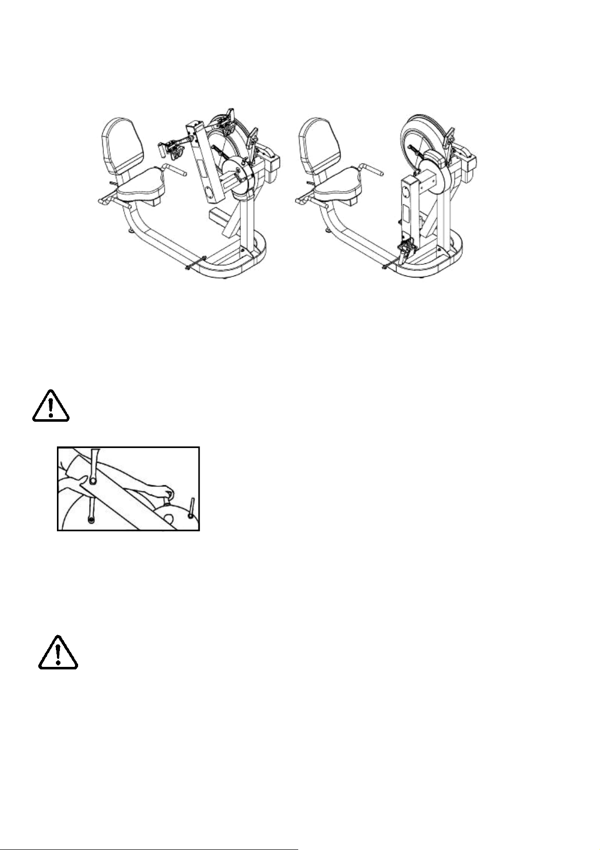
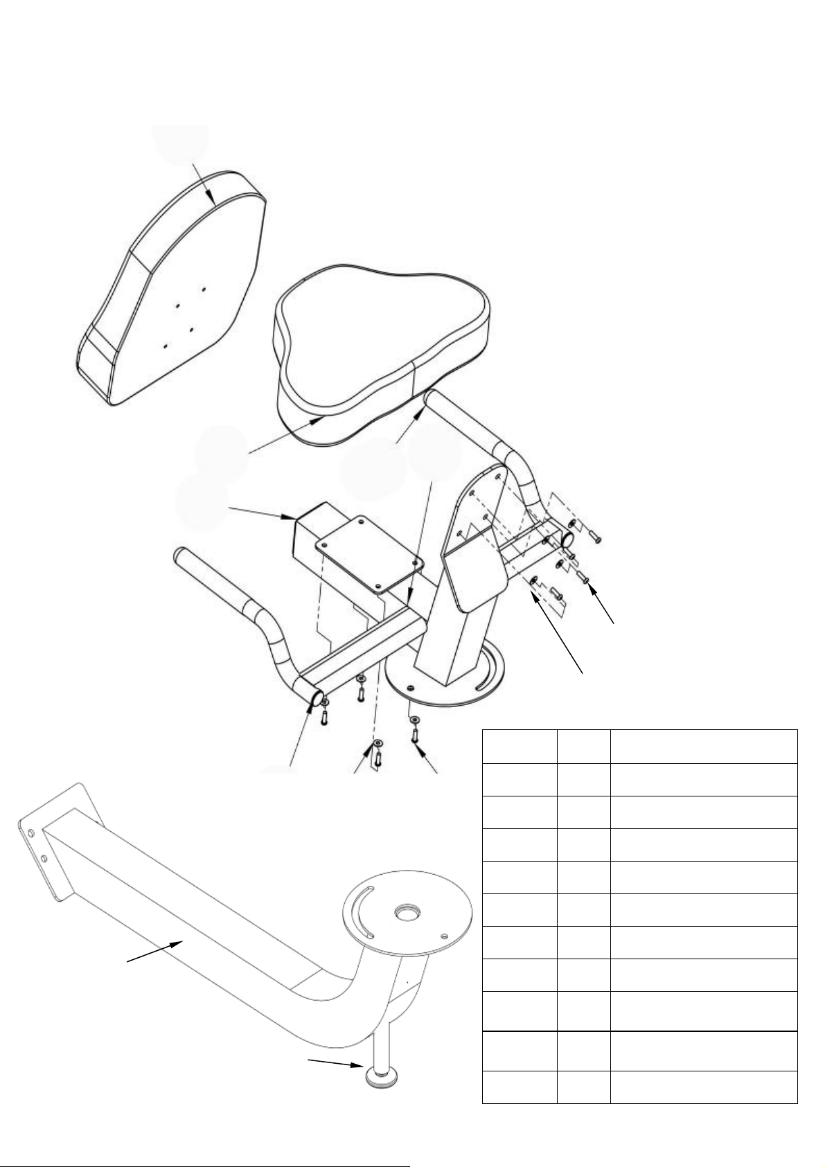
The E720 Control Arm
The E720 Pedal: This pat-
ented design allows for usage
in both the recumbent posi-
tion and for sitting/standing
upper body workouts.
L-pin: Loosen when
rotating the control
arm and tighten (snug
only) once the de-
sired position has
been reached.
T-pin: The T-pin locks the control
arm in any one of 72 different posi-
tions throughout its 360 degree
range of motion. Pull up the T-pin
to allow the control arm to rotate
while supporting the control arm
with the other hand.
Crank arm bolts:
Loosen all 8 bolts slightly
before adjusting/
tightening chain.
Inspection plate: Open to check
chain tension.
Warning: Do not check
chain tension by hand!
Chain tensioning bolts: Allows for tightening the chain or adjustment from side to side. Make sure
when tightening only to adjust the same amount for both bolts, otherwise the sprocket will be mis-
aligned.
Note: Tightening the right bolt only will pull the right side of the crank assembly toward you, tighten-
ing the left will pull the left side toward you. Use this feature to realign the rear with the front sprocket
if needed or when changing to a new chain.

11
Item Timeframe Instructions Notes
Seat and Frame. Weekly. Wipe down weekly with
lint free cloth or more
often with heavy club
use.
PK belt tension. Monthly. Check monthly for signs
of slippage. Adjust/
tighten as required.
Tank and water treat-
ment. 12 months to 2 years. Follow instructions as
specified in the “Water
Treatment” section of
this manual.
Chain drive. Check every 100 hours
for correct tension. Open the inspection
plate and check tension
using a screwdriver or
other tool. Tighten as
required using chain
tensioning bolts located
at the end of the control
arm.
E720 pedals. Tighten weekly using
15mm box wrench
(supplied)
The pedals should be
checked on a regular
basis. A loose pedal
can cause damage to
the crank arm aluminum
threads, requiring re-
placement.
Maintenance chart.

12
Fault Probable
Cause Solution
Water changes color or be-
comes cloudy. Rower is in direct
sunlight or has not
had water treatment.
Change rower location to reduce direct
exposure to sunlight. Add water treat-
ment or change tank water as directed
in the water treatment section of this
manual.
Knocking noise from inside
the control arm while train-
ing, especially when chang-
ing directions.
Chain requires tight-
ening or adjustment. Open inspection plate located on front
of control arm and check tension using a
screwdriver or other tool. Use the chain
tensioning bolts located at the rear of
the control arm to tighten or adjust as
needed. The chain should have approx
3mm of slack when properly adjusted.
See P.10 for details.
Pedals slip during hard
training. PK tank belt requires
tightening. Remove large inspection plate next to
the tank, insert a long tool to push the
rear end cap out from the inside, expos-
ing the tank belt tensioning bolt. Loosen
tank bolts slightly. Remove upper rub-
ber belt cover to expose the PK belt.
Tighten the tank tensioning bolt until the
belt is too tight to be twisted from side to
side more than 45 degrees by hand.
See P.14 for details
Pedal is loose (either left or
right) and cannot be retight-
ened.
Aluminum crank arm
threads are stripped.
Contact service center for replacement.
Then check weekly as recommended.
Computer screen illumi-
nates, but does not register
when rowing.
Loose or failed con-
nection/Sensor gap
too wide (see erratic
computer display).
Check that the computer lead is con-
nected properly. If connected properly
check sensor gap. Contact your local
service center if this fails to address the
problem.
The E720 computer does
not illuminate after battery
installation.
Batteries installed in-
correctly or need re-
placing.
Reinstall batteries in correct position and
try again. If the LCD screen fails to illu-
minate, try rotating the batteries slightly
in the computer. If this fails, contact
your local service center.
The E720 computer display
is erratic/slow while display-
ing RPM and WATTS
Gap between sensor
and magnetic ring is
too wide.
Remove inspection plate and check sen-
sor gap and that magnetic ring is not
wobbly.
Troubleshooting guide:

13
E720 Ergometer.
Quick start provides instant workout infor-
mation. Just start training to activate. You
can choose to change UNITS displayed.
UNITS
displays
WATTS,
RPM,
HR,
MPH,
Level Adjustable
from 1-20 Set Changes Time, Distance
parameters
Program Clears current
exercise program
Note: For complete operational
instructions, please refer to the
computer manual, which is in-
cluded with your E720.
Reset Clears
data

14
The USB connectivity now built in to all new models of FDF Console and IPM allow you
to enhance your exercise experience by connecting to your home PC or Laptop. Using
FDF's own sample applications you can exercise while enjoying your favorite movies.
NetAthlon 2 XF for Rowers lets you race with other Internet connected rowers in a Virtual
Reality 3D environment or train solo.
1. Download and Install the USB Device Driver (CDM2xxxx_Setup.exe for 32 and 64 bit
Windows 7/Vista/XP) from the FDF Website.
2. Download and Install the Sample USB Applications from the FDF Website
(www.firstdegreefitness.com).
Download and Install NetAthlon 2 XF for Rowers from
http://www.webracing.org/downloads.htm
- The USB Connector is located on a flying lead at the rear of the IPM, along with the
Sensor and Heart Rate Monitor Connectors.
- Connect to a Laptop or PC using a standard USB cable, you may need to wait while
Windows starts the USB Device Driver.
Using the First Degree Fitness USB Interface
Description:
Setting up USB connectivity
Connecting your
Note: Please refer to computer manual where applicable or for further information
refer to our website at www.firstdegreefitness.com
15
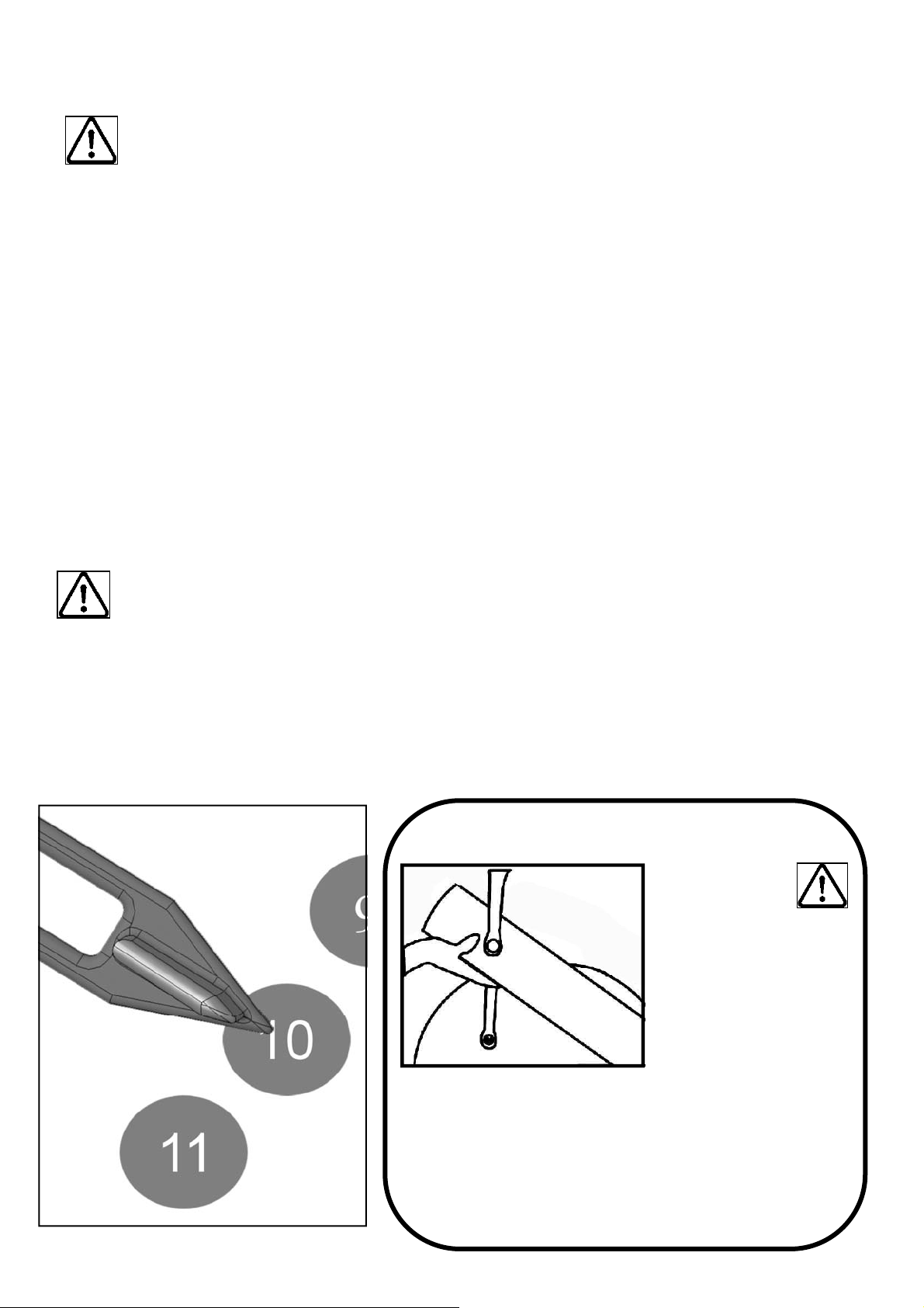
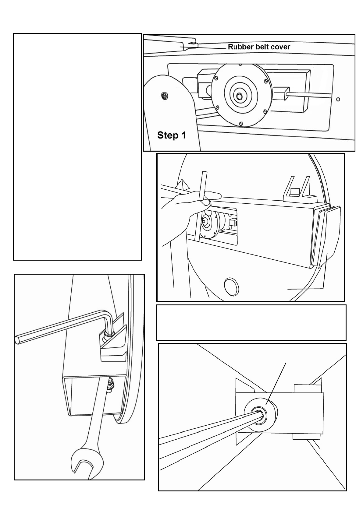
Step 1: Remove large metal in-
spection plate as shown above
right.
Step 2: Using a long tool, push
out the rear end cap as pictured
right. This will give you access
to the tank tensioning bolt
(shown bottom right).
Step 3: Loosen both the front
and rear tank bolts as shown
below. Remove front rubber belt
cover.
Step 4: Using a 6mm Allen key,
tighten the belt using the tank
tensioning bolt until the belt no
longer slips during hard rowing.
Note: Do not over tighten
tank bolts.
Step 3 Step 4
Tank tensioning bolt
Tank Belt Adjustment
Step 2 End Cap
Tip: Twist the belt by hand to gauge tightness.
Correct tension should be obtained when no
longer able to twist more than 45 degrees.
16
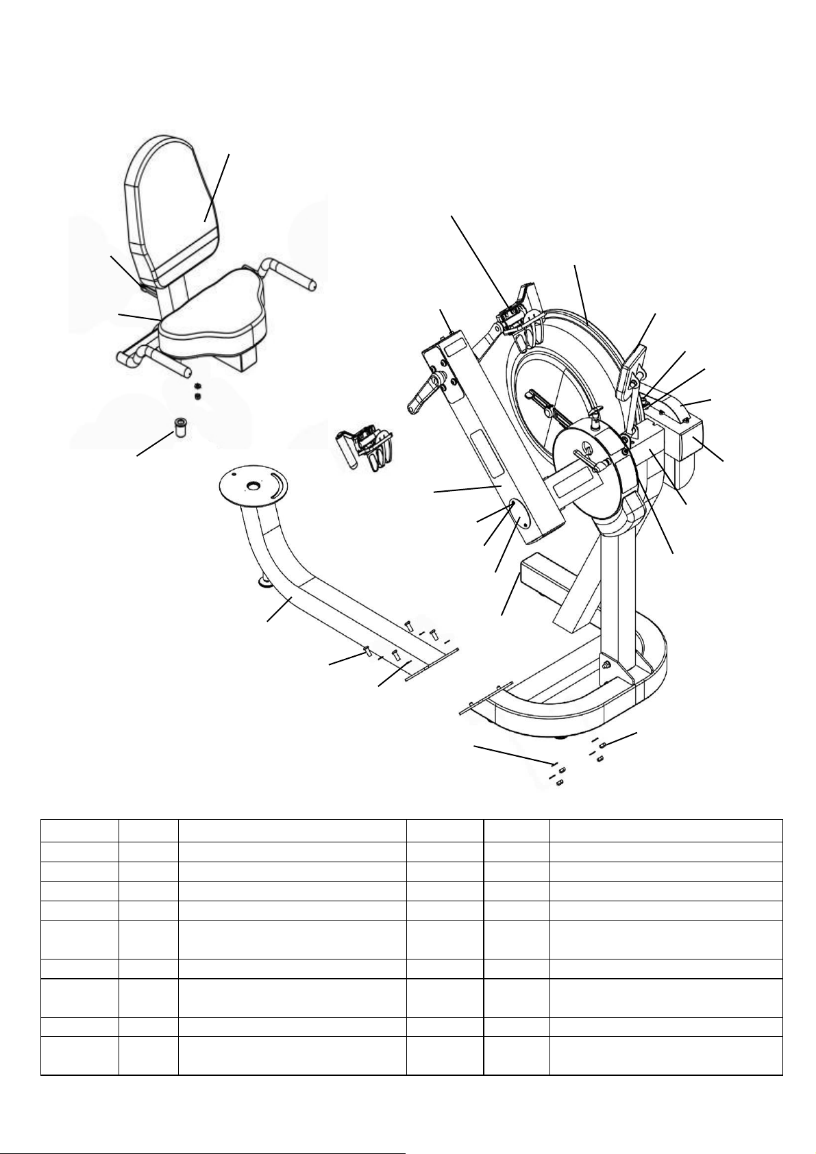
E720 Exploded Diagram:
P/N QTY Description P/N QTY Description
10040 1 Bolt M12x140 10170 6 Washer M4
10041 6 Nut M10 Nylock 23008 1 End Cap 75x75 Rubber
10043 6 Washer M12 20163 2 Semi Circle Cover
10066 3 End Cap 100x100mm 20850 1 Tension Adjustment
10067 2
Rubber Cover for Large PK
Pulley 23045 1 L Pin M10x35
10070 18 Screw M4x10 33100 1 Main Frame Assembly
10072 2
Small Steel Side Cover
100mm 33913 1 Plastic Spacer 10x25x4T
10082 9 Washer M10 33915 1 Oil Bushing
10139 2 Spring Washer Flywheel Shaft 71025 2 M10x25mm Main Shaft Rear
Bracket Bolt
10066
33100
10170
Refer to Control
Arm Assembly
Refer to A010
Tank Assembly
20850 Refer to Computer
Assembly
10040
10043
10067
20163
10070
10072
10082 10041
23008
71025 10139
Refer to Seat Frame
Assembly
Refer to A037/A038
Left & Right Pedal
Assembly
33915
23045
33913
Refer to Seat
Frame Assembly
17
Upper/Lower Mainframe:
20014
23008
10082
20024
33101
73016
20009
10041
20101
10041
10082
10082
30010
P/N QTY Description
20101 1 Upper Main Frame
10082 8 Washer M10
20024 1 Number Decal
33101 1 Lower Main Frame
73016 4 Foot Levelers M8x30 PVC
10041 4 Nut M10 Nylock
20009 4 Bolt M10x100
20014 1 Right Bottom Frame
30010 1 Left Bottom Frame
23008 1 End Cap 75x75 Rubber

18
Refer to Crank Arm
Assembly
20850
20163
10066
Refer to Control Arm
Assembly
10170
30012
10070
Refer to Main Drive
Assembly
Control Arm (external) Assembly:
P/N QTY Description
30012 1 DID-25 Chain 178
10066 1 End Cap 100mm
10170 2 Washer M4
10070 2 Screw M4x10
20163 2 Semi Circle Cover
20850 1 Tension Adjustment
19
73016
33902
Seat Frame Assembly:
10080
10081
30014
20008
33910
30002
20115
20117
10080
10081
P/N QTY Description
20115 1 Seat LS-622
20117 1 Seat Back LS-622
10080 8 Bolt M6x20
10081 8 Washer M6
20008 1 End Cap 75x75 PVC
30014 2 End Cap
30002 2 Handle Grip
33910 1 Rotating Seat Frame
Upper
73016 1 Foot Levelers M8x30
PVC
33902 1 Seat Lower Frame

20
50903
10096
10117
10097
10116
10082
10114
13112
10114
10082
Computer Assembly
20068
10083
10041
20125
20045
30013
20170
10083
10082
20151
20020
20151
20064 20174
20151
10120 20170
20170
20170
20151
20032 20033
20036
20291
Control Arm Assembly
P/N QTY Description P/N QTY Description
10041 1 Nut M10 Nylock 20045 1 L-Pin M12x40
10082 1 Washer M10 20064 1 Weight Block
10083 2 Bolt M10x20 20068 1 T-Pin
10120 1 Screw M6x15 20125 1 Plastic Washer 30*6*6
20020 1 Bolt M10x35 20151 4 Washer M10
20032 1 Warning Decal 20170 4 Chain Protection Decal
20033 1 Arm Moving Decal 20174 1 Eccentric Bushing
20036 1 Small Warning Decal 20291 1 Rotating Arm
30013 1 CXT Decal
P/N QTY Description
13112 1 Computer Mounting Arm
10114 4 Bushing 20x16x13x10
10082 4 Washer M10
10116 1 Bolt M10x60
10097 2 Nut Dome Head M10
10117 1 Computer Wiring 1200
10096 1 Bolt M10x70 for Aluminum Rail
50903 1 Computer
Table of contents
Other Activeforever Fitness Equipment manuals


Popular Fitness Equipment manuals by other brands


Merrithew Health & Fitness
Merrithew Health & Fitness STOTT PILATES Foam Roller quick start guide

Finnlo
Finnlo 3869 manual

Weider
Weider Pro 550 Bench Gebruikershandleiding

FlintRehab
FlintRehab Cycli user guide

SPALDING
SPALDING M8872411 owner's manual

FF Europe
FF Europe physionics HNTLB03 Original operating instructions