Activeforever Pro XP 556 User manual
Owner's
Manual
! WARNING !
Exercise can present a health
risk. Consult a physician
beforebeginningany exercise
program with this equipment.
If you feel faint or dizzy,
immediately discontinue use
of this equipment. Serious
bodily injury can occur if this
equipment is not assembled
and used correctly. Serious
bodily injury can also occur if
all instructions are not
followed. Keep others and
pets away from equipment
when in use. Always make
sure all bolts and nuts are
tightened prior to each use.
Followallsafetyinstructionsin
this manual.
When calling for parts or
service, please specify the
following number.
55-5556
Patent No. 7,179,207.
Other Patents Applied
and Are Pending.
MADE IN CHINA
CAUTION:
Weight on this product should not exceed 300 lbs.
Product May Vary Slightly
From Pictured.
2007, 12 2007 Stamina Products, Inc.

TABLE OF CONTENTS
2
Page Page
Before starting any exercise or conditioning program you should consult with your personal
physician to see if you require a complete physical exam. This is especially important if you
are over the age of 35, have never exercised before, are pregnant, or suffer from any
illness. READ AND FOLLOW THE SAFETY PRECAUTIONS. FAILURE TO FOLLOW
THESE INSTRUCTIONS CAN RESULT IN SERIOUS BODILY INJURY.
SAFETY INSTRUCTIONS
WARNING:
1.
2.
3.
4.
5.
6.
7.
8.
9.
10.
11.
12.
13.
14.
15.
16.
17.
18.
We recommend that two people be available for assembly of this product.
Read all warnings posted on the AeroPilates Pro XP556.
Read this Owner's Manual and follow it carefully before using the AeroPilates Pro XP556. Make
sure that it is properly assembled and tightened before use.
When exercising on this product, do not exercise at an intensity that causes the product itself to
move. This could result in damage to your joints and the product.
Keep children away from the AeroPilates Pro XP556. Do not allow children to use or play on the
AeroPilates Pro XP556. Keep children and pets away from the AeroPilates Pro XP556 when
it is in use.
It is recommended that you place this exercise equipment on an equipment mat.
Set up and operate the AeroPilates Pro XP556 on a solid level surface. Do not position the
AeroPilates Pro XP556 on loose rugs or uneven surfaces.
Make sure that adequate space is available for access to and around the AeroPilates Pro XP556.
Inspect the AeroPilates Pro XP556 for worn or loose components prior to use.
Tighten/replace any loose or worn components prior to using the AeroPilates Pro XP556.
Consult a physician prior to commencing an exercise program. If, at any time during exercise, you
feel faint, dizzy, or experience pain, stop and consult your physician.
Follow your physician's recommendations in developing your own personal fitness program.
Always choose the workout which best fits your physical strength and flexibility level. Know your
limits and train within them. Always use common sense when exercising.
Do not wear loose or dangling clothing while using the AeroPilates Pro XP556.
Be careful to maintain your balance while using, mounting, dismounting, or assembling the
AeroPilates Pro XP556, loss of balance may result in a fall and serious bodily injury.
The AeroPilates Pro XP556 should not be used by persons weighing over 300 pounds.
The AeroPilates Pro XP556 should be used by only one person at a time.
The AeroPilates Pro XP556 is for consumer use only. It is not for use in public or semipublic
facilities.
WARNING:
To reduce the risk of serious injury, read the following Safety Instructions before
using the AeroPilates Pro XP556.
Maintenance 12
Conditioning Guidelines 13
Warm-Up and Cool-Down 14
Warranty 15
Product Parts Drawing 16
Parts List 17
Fax/Mail Ordering Form 19
Safety Instructions 2
Before You Begin 4
Equipment Warning & Notice Labels 5
Hardware Identification Chart 6
Assembly Instructions 7
Operational Instructions 10
Storage 12
4
THE FOLLOWING TOOLS ARE INCLUDED FOR ASSEMBLY :
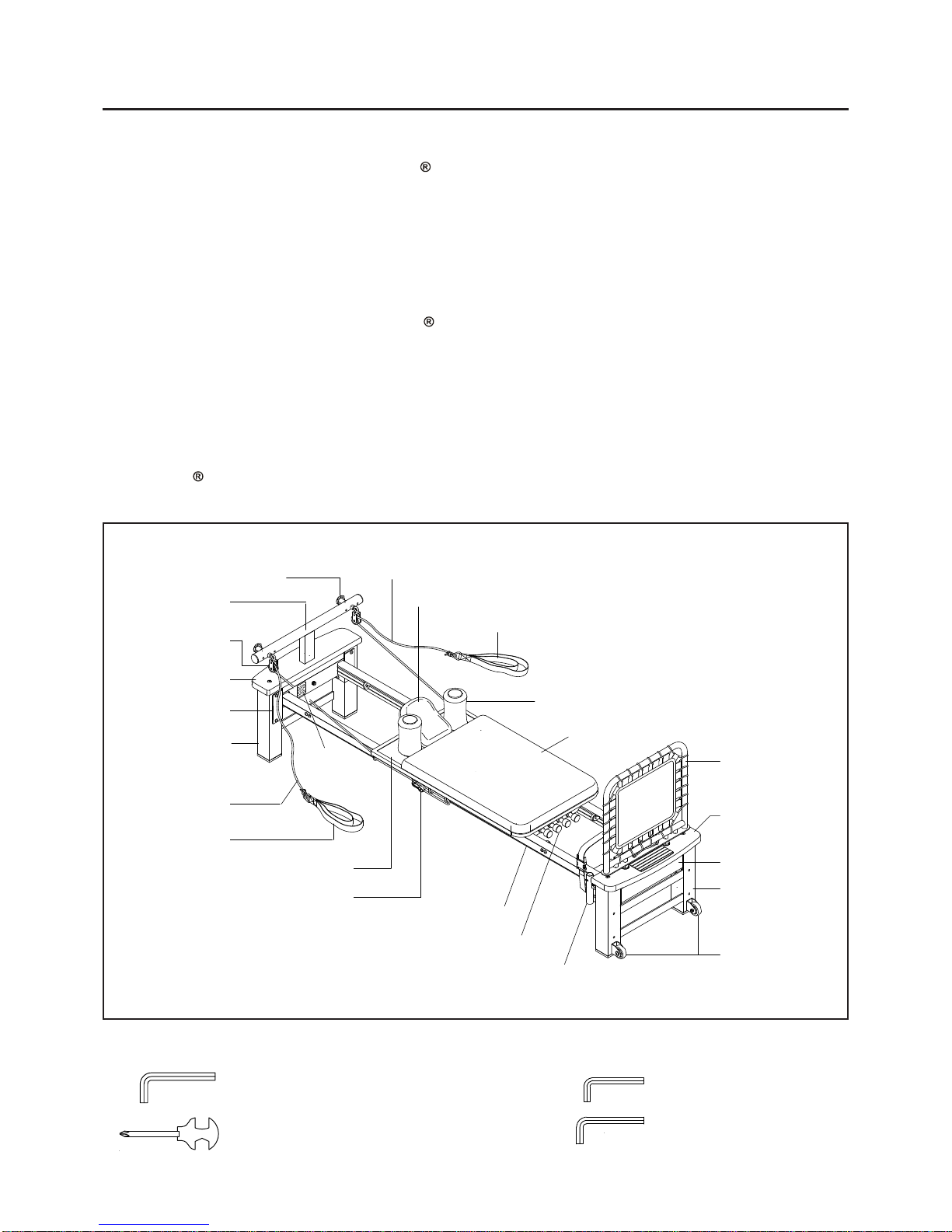
BEFORE YOU BEGIN
Rope
Front Wooden
Platform
Front Brace
Pulley Post
Rear Leg
Hand Strap
Tension Cord
Front Right Rail
Plastic Snap Hook
Carriage
Cushion
Foam Pad
Headrest
Hand Strap
Cardio
Rebounder
Rope
Warning
Label
Rear Wooden
Platform
Pulley Set
Wheels
Right Footbar Support
Thank you for choosing the AeroPilates Pro
XP556. We take great pride in producing this quality
productandhopeitwillprovide manyhoursof quality
exerciseto makeyou feelbetter,look betterandenjoy
life to its fullest.
Yes, it's a proven fact that a regular exercise
program can improve your physical and mental
health. Too often, our busy lifestyles limit our time
and opportunity to exercise. The AeroPilates Pro
XP556 provides a convenient and simple method to
beginyourassaulton getting your body in shapeand
achieving a happier and healthier lifestyle.
Before reading further, please review the drawing
below and familiarize yourself with the parts that are
labeled.
Read this manual carefully before using the
AeroPilates Pro XP556.
Although Stamina constructs its products with the
finest materials and uses the highest standards of
manufacturing and quality control, there can
sometimes be missing parts or incorrectly sized
parts. If you have any questions or problems with
the parts included with your AeroPilates Pro
XP556, please do not return the product. Contact us
FIRST!
If a part is missing or defective, please call us toll
free at 1-800-375-7520 (in the U.S.). Our Customer
ServiceStaffisavailabletoassistyou from 7:30A.M.
to5:00P.M.(CentralTime)MondaythroughThursday
and 8:00A.M. to 3:00 P.M. (Central Time) on Friday.
If you would like to contact us online, go to our
websiteat www.staminaproducts.comandaccessthe
Customer Service section.
Be sure to have the name and model number of
the product available when you contact us.
Adjustment Knob
Allen Wrench (5mm)
Allen Wrench (6mm)
Allen Wrench (8mm)
Combination Wrench
Rear Brace
Front Leg
5
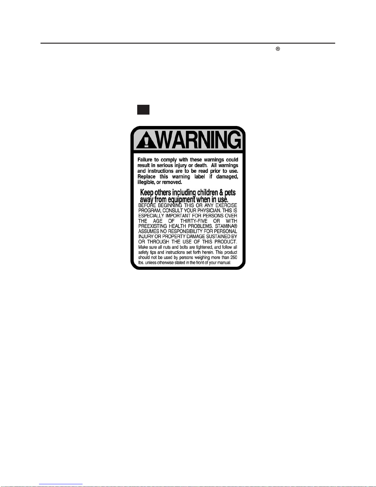
EQUIPMENT WARNING & NOTICE LABELS
This chart is provided to help identify the warning & notice labels on the AeroPilates Pro XP556. Please
take a moment to familiarize yourself with all of the warning & notice labels.
Label is larger than actual size
WARNING LABEL(75)
W1
6
Part No. and Description Qty
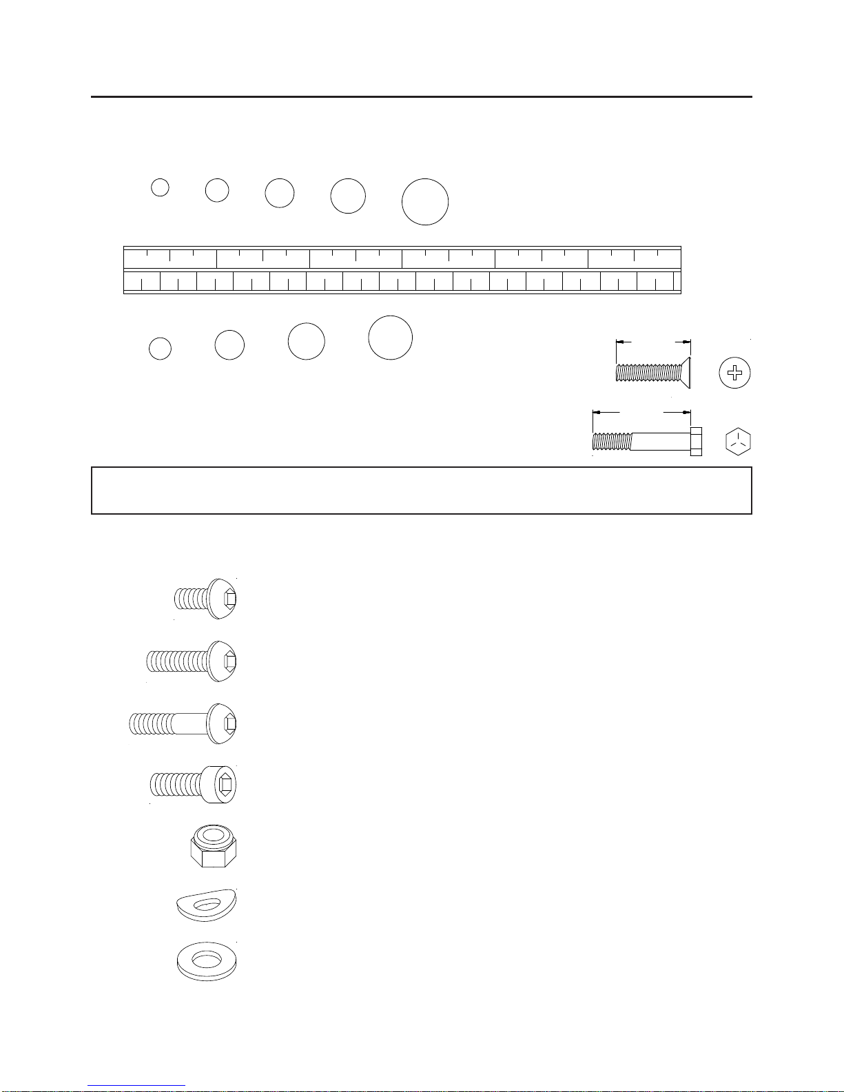
HARDWARE IDENTIFICATION CHART
This chart is provided to help identify the hardware used in the assembly process. Place the washers, the
end of the bolts, or screws on the circles to check for the correct diameter. Use the small scale to check the
length of the bolts and screws.
NOTICE: The length of all bolts and screws except those with flat heads is
measured from below the head to the end of the bolt or screw.
Flat head bolts and screws are measured from the top of the
head to the end of the bolt or screw.
mm.
in.
INCHES
MILLIMETERS
11/2021/2 31/2 41/2 51/2 61/2
0 10 20 30 40 50 60 70 80 90 100 110 120 130 140 150
6 8 10 12
3/16" 5/16" 1/2"3/8"1/4"
length
length
After unpacking the unit, open the hardware bag and make sure that you have all the following items.
Some hardware may be already attached to the part.
52 Bolt, Button Head (M8 x 1.25 x 20mm) 16
53 Bolt, Button Head (M8 x 1.25 x 24mm, with threadlocker) 4
54 Bolt, Button Head (M8 x 1.25 x 30mm) 4
56 Bolt, Button Head (M8 x 1.25 x 42mm) 2
57 Bolt, Socket Head (M10 x 1.5 x 35mm) 1
51 Bolt, Button Head (M8 x 1.25 x 10mm, with threadlocker) 24
67 Nylock Nut (M8 x 1.25) 2
70 Arc Washer (M8) 2
73 Washer (M8) 2
ASSEMBLY INSTRUCTIONS
7
Place all parts from the box in a cleared area and position them on the floor in front of you. Remove all
packing materials from your area and place them back into the box.Do not dispose of the packing materials
until assembly is completed. Read each step carefully before beginning. If you are missing a part please call
our toll-free number for assistance 1 (800) 375-7520 or e-mail us at: parts@staminaproducts.com
1.
2.
REAR
FRONT
Mark "A"
NOTE: We recommend that two people be available for assembly of this product.
STEP 1
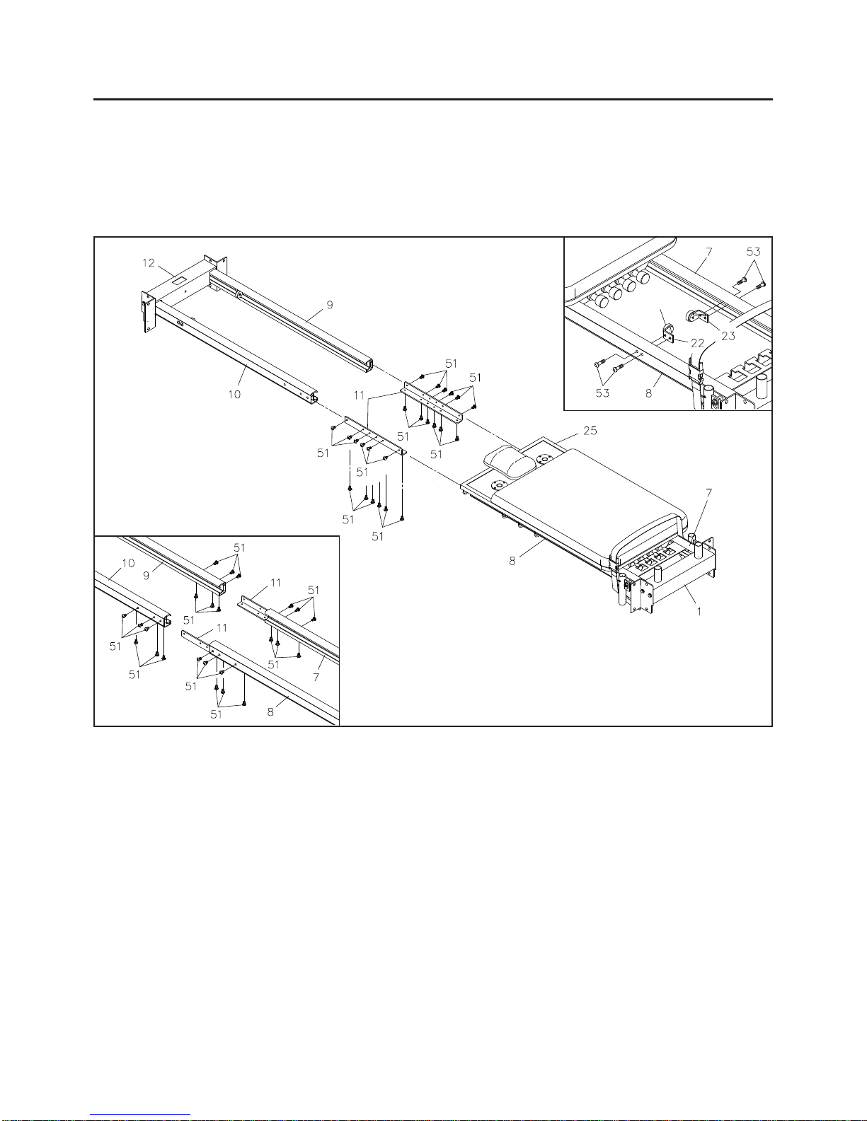
Refer to illustration 1. To connect the RAILS: Insert the CONNECTING BRACKETS(11) into the FRONT
LEFT RAIL(7) and FRONT RIGHT RAIL(8) and secure with BUTTON HEAD BOLTS(M8x1.25x10mm)(51).
Do not tighten the bolts until STEP 2.
STEP 2
Insert the CONNECTING BRACKETS(11) into the REAR LEFT RAIL(9) and REAR RIGHT RAIL(10) and
secure with BUTTON HEAD BOLTS(M8x1.25x10mm)(51). Tighten all of the bolts.
STEP 3
Refer to illustration 2. There is an "A" decal on the STOP BRACKET A(22) and a "B" decal on the STOP
BRACKET B(23). Move the CARRIAGE(25 ) toward the REAR BRACE(12). Attach the STOP BRACKET
A(22) to the FRONT RIGHT RAIL(8) with BUTTON HEAD BOLTS(M8x1.25x24mm)(53).Attach the STOP
BRACKET B(23) to the FRONT LEFT RAIL(7) with BUTTON HEAD BOLTS(M8x1.25x24mm)(53).
ASSEMBLY INSTRUCTIONS
8
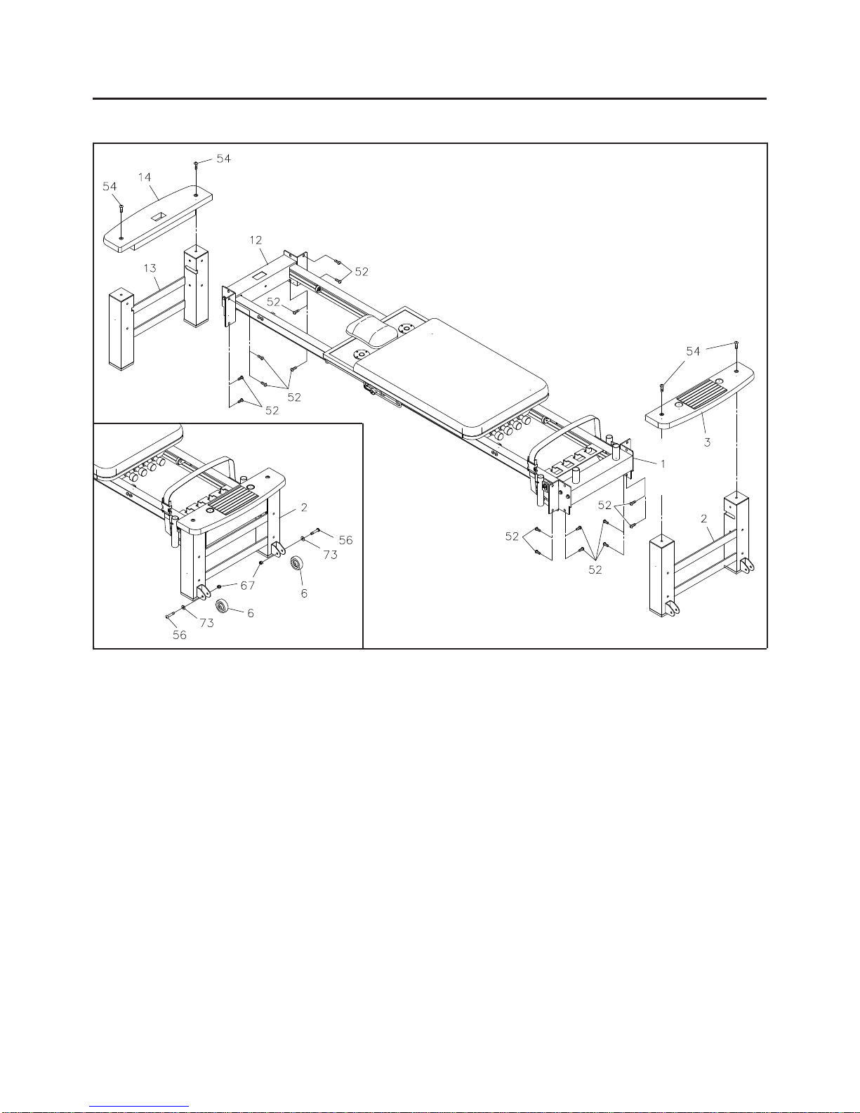
STEP 4
Slide the FRONT LEG(2) onto the FRONT BRACE(1) as shown in the illustration and secure with BUTTON
HEAD BOLTS(M8x1.25x20mm)(52). Do not tighten bolts until STEP 5 is complete.
STEP 5
Slide the REAR LEG(13) onto the REAR BRACE(12) as shown in the illustration and secure with BUTTON
HEAD BOLTS(M8x1.25x20mm)(52). Tighten all of the bolts.
STEP 6
Attach the FRONTWOODEN PLATFORM(3) tothe top of the FRONT LEG(2) withBUTTON HEAD BOLTS
(M8x1.25x30mm)(54).
Attach the REAR WOODEN PLATFORM(14) to the top of the FRONT LEG(13) with BUTTON HEAD
BOLTS(M8x1.25x30mm)(54).
STEP 7
Attach the WHEELS(6) to the FRONT LEG(2) with BUTTON HEAD BOLTS(M8x1.25x42mm)(56),
WASHERS(M8)(73), and NYLOCK NUTS(M8x1.25)(67).

ASSEMBLY INSTRUCTIONS
9
BUTTON
PIN(19)
STEP 9
Insert the PULLEY POST(36) into the REAR WOODEN PLATFORM(14) and secure with SOCKET
BOLT(M10x1.5x35mm)(57). Insert the PULLEY SETS(38) through the PULLEY SPACERS(39) and the
PULLEY POST(36) and secure with ADJUSTMENT KNOBS(40) and ARC WASHERS(M8)(70).
STEP 10
Screw the two FOAM PADS(34) into the CARRIAGE(25).
STEP 11
The FOOTBAR(17) and the CARDIO REBOUNDER(46) cannot be used at the same time. For cardio
workouts, install the CARDIO REBOUNDER(46) and for Pilates workouts, install the FOOTBAR(17).
Refer to the inset drawing.To install the CARDIO REBOUNDER(46), insert the CARDIO REBOUNDER
(46) posts into the holes in the FRONT WOODEN PLATFORM(3).
3.
Toinstallthe FOOTBAR(17), inserttheFOOTBAR(17) intotheLEFT andRIGHTFOOTBAR SUPPORTS
(15, 16) and slide down until BUTTON PINS(19) lock into position.
1.
To remove the FOOTBAR(17), grasp the FOOTBAR(17) on both sides close to the FOOTBAR
SUPPORTS(15, 16). Press the BUTTON PINS(19) at the same time, pull up, and remove.
2.
10
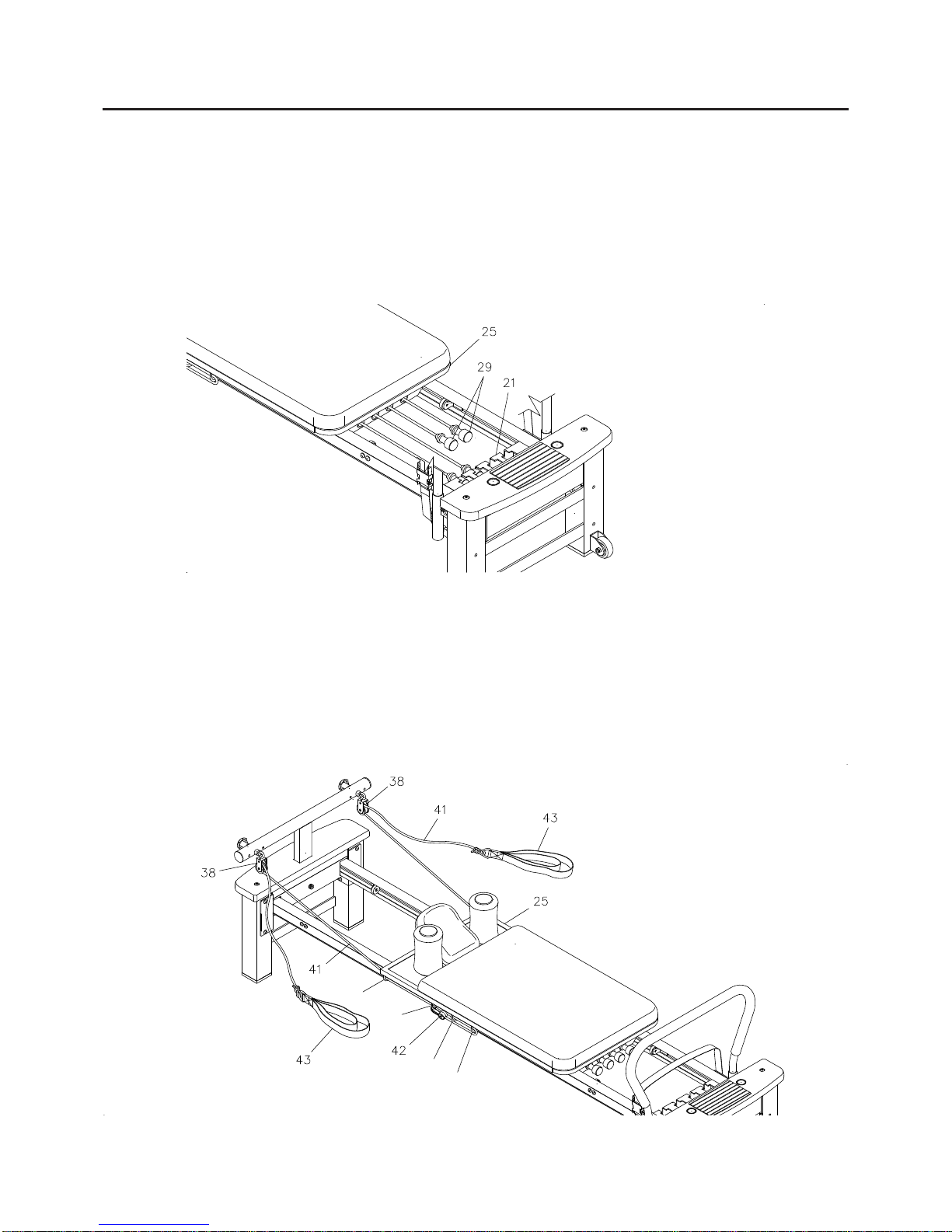
ROPE LENGTH ADJUSTMENT
The ROPES(41) feed through the PULLEY SETS(38) then thread through the loops on the underside of
both outer edges of the CARRIAGE(25). PLASTIC SNAP HOOKS(42) on the end of each rope are used to
adjust the ROPE(41) length. If more length is needed, attach the PLASTIC SNAPHOOKS(42) to loopD.To
shorten, bring the ROPES(41) around the last loop D and secure to loops A, B, or C with the PLASTIC
SNAP HOOKS(42). Wrap ROPES(41) through the loops and attach where needed to shorten ROPES(41)
even more.
B
D
C
A
OPERATIONAL INSTRUCTION
LOAD ADJUSTMENT
The resistance of the CARRIAGE(25) can be adjusted by securing the TENSION CORDS(29) in the slots
on the CORD HOLDER(21). You can achieve various levels of resistance by securing different numbers of
the TENSION CORDS(29) in the slots.
NOTE: OvertimeyourTENSIONCORDS(29)willrelax.Toincreaseresistance intheTENSION CORDS(29),
stretch and re-tie the tension cords in a more taut position.

11
FORWARD
POSITION
PIN
SLOT
Support
Bracket
OPERATIONAL INSTRUCTION
HEADREST ADJUSTMENT
The HEADREST(32) on the CARRIAGE(25) can be positioned
flat or at an incline by simply pivoting the support bracket
underneath the HEADREST(32).
FOOTBAR ADJUSTMENT
The FOOTBAR(17) can be positioned at three angles. Lift the
FOOTBAR(17) until the pins come out of the slots on the FRONT
BRACE(1). Move the FOOTBAR(17) to the desired position and
lock the FOOTBAR(17) in position by pushing it down so that the
pins are in the slots on the FRONT BRACE(1).
NOTE:
PULLEY ADJUSTMENT
There are three adjustment holes on each side of the PULLEY
POST(36) forattachingthe PULLEY SETS(38)in differentwidths.
Remove the ADJUSTMENT KNOBS(40) and ARC WASHERS
(M8)(70) from the PULLEY POST(36). Attach the PULLEY
SETS(38) to the position you want and secure with the
ADJUSTMENT KNOBS(40) and ARC WASHERS(M8)(70).
NOTE:
Always make sure the pins are locked into the slots properly.
Use forward position of the FOOTBAR(17) when standing on
the AeroPilates Pro XP556 with one foot on the FRONT
WOODEN PLATFORM(3).
1.
2.
Always use the same adjustment holes for both sides.

STORAGE
Store the AeroPilates Pro XP556 in a clean, dry place.
It is recommended that two people be available to move the AeroPilates Pro XP556.
To move the AeroPilates Pro XP556: First, attach one of the TENSION CORDS(29) in the slot on
the CORD HOLDER(21) to prevent the CARRIAGE(25) from moving. Second, grasp the PULLEY
POST(36) and lift the unit from the back. Third, roll the AeroPilates Pro XP556 on the moving wheels
that are attached to the FRONT LEG(2).
1.
2.
3.
MAINTENANCE
The safety and integrity designed into the AeroPilates Pro XP556 can only be maintained when the
AeroPilates Pro XP556 is regularly examined for damage and wear. Special attention should be given to
the following:
It is the sole responsibility of the user/owner to ensure that regular maintenance is performed.
Wornordamagedcomponentsshould bereplaced immediatelyorthe AeroPilates ProXP556removed
from service until repair is made.
Verify that the Warning Label is present and legible. Replace the Warning Label if it is missing or
damaged.
Verify that the ROPES(41) are properly installed on the PULLEY SETS(38).
Check the condition of the ROPES(41) and replace if they are frayed or worn.
Check the PLASTIC SNAP HOOKS(42) on the ends of the ROPES(41). Replace the ROPES(41) if
PLASTIC SNAP HOOKS(42) are damaged or deformed.
Check the TENSION CORDS(29). If a TENSION CORD(29) is stretched and loose, re-tie the knot on
the end of the cord. Replace TENSION CORDS(29) that are frayed or worn.
Check the BUNGEE CORD(48) on the CARDIO REBOUNDER(46) for wear. Replace the CARDIO
REBOUNDER(46) if the BUNGEE CORD(48) is frayed or worn.
Check the PULLEY SETS(38) for excessive wear. Replace worn PULLEY SETS(38).
Check the HAND STRAPS(43) for damage. Replace damaged parts.
Check the FOAM SLEEVE(18) and FOAM PADS(34) and replace if damaged or worn.
Check the STOP PLATES(22, 23) for looseness or damage and replace any damaged parts.
Check the CUSHION(28) and replace if it is damaged or worn.
Check and clean the ROLLERS(26) and the rolling surfaces on the rails. Clean by wiping with a dry
cloth.
Only Stamina Products supplied components shall be used to maintain/repair the AeroPilates Pro
XP556.
Keep your AeroPilates Pro XP556 clean by wiping with an absorbent cloth after use.
1.
2.
3.
4.
5.
6.
7.
8.
9.
10.
11.
12.
13.
14.
15.
16.
12

13
CONDITIONING GUIDELINES
How you begin your exercise program depends on your physical condition. If you have been inactive for
several years or are severely overweight, start slowly and increase your workout time gradually. Increase
your workout intensity gradually, too, by monitoring your heart rate while you exercise.
Initially you may only be able to exercise within your target zone for a few minutes; however, your aerobic
capacity will improve over the next six to eight weeks. It is important to pace yourself while you exercise so
you don’t tire too quickly.
Measure your heart rate periodically during your workout by stopping the
exercise but continuing to move your legs or walk around. Place two or three
fingers on your wrist and take a six second heartbeat count. Multiply the
resultsby ten to find your heartrate. For example, if your six secondheartbeat
count is 14, your heart rate is 140 beats per minute. A six second count is
used because your heart rate will drop rapidly when you stop exercising.
Adjust the intensity of your exercise until your heart rate is at the proper level.
wrist pulse
Have your doctor review your training and diet programs.
Begin your training program slowly with realistic goals that have been set by you and your physician.
Warm up before you exercise and cool down after you work out.
Take your pulse periodically during your workout and strive to stay within a range of 60% (lower
intensity) to 90% (higher intensity) of your maximum heart rate zone. Start at the lower intensity and
build up to higher intensity as you become more aerobically fit.
If you feel dizzy or lightheaded you should slow down or stop exercising.
Target Heart Rate Zone Estimated by Age*
Remember to follow these essentials:
To determine if you are working out at the correct intensity, use a heart rate monitor or use the table below.
For effective aerobic exercise, your heart rate should be maintained at a level between 60% and 90% of
your maximum heart rate. If just starting an exercise program, work out at the low end of your target heart
ratezone. Asyour aerobiccapacity improves, graduallyincreasethe intensity of yourworkout byincreasing
your heart rate.
Forcardiorespiratorytrainingbenefits,theAmerican College ofSportsMedicine recommendsworking
out within a heart rate range of 55% to 90% of maximum heart rate. To predict the maximum heart
rate, the following formula was used: 220 - Age = predicted maximum heart rate
*
20 years
25 years
30 years
35 years
40 years
45 years
50 years
55 years
60 years
65 years
70 years
Target Heart Rate Zone
(55%-90% of Maximum Heart Rate) Average Maximum
Heart Rate 100%
Age
110-180 beats per minute
107-175 beats per minute
105-171 beats per minute
102-166 beats per minute
99-162 beats per minute
97-157 beats per minute
94-153 beats per minute
91-148 beats per minute
88-144 beats per minute
85-139 beats per minute
83-135 beats per minute
200 beats per minute
195 beats per minute
190 beats per minute
185 beats per minute
180 beats per minute
175 beats per minute
170 beats per minute
165 beats per minute
160 beats per minute
155 beats per minute
150 beats per minute

14
WARM-UP and COOL-DOWN
Warm-Up The purpose of warming up is to prepareyour body forexerciseand to minimizeinjuries.Warm
up for two to five minutes before strength-training or aerobic exercising. Perform activities that raise your
heartrate andwarm the working muscles. Activities may includebrisk walking,jogging, jumping jacks,jump
rope, and running in place
Stretching Stretching while your muscles are warm after a proper warm-up and again after your strength
or aerobic training session is very important. Muscles stretch more easily at these times because of their
elevatedtemperature,whichgreatlyreducesthe riskofinjury. Stretchesshould beheldfor15to 30 seconds.
Do not bounce.
Suggested Stretching Exercises
Remember always to check with your physician before starting any exercise program.
Cool-Down The purpose of cooling down is to return the body to its normal, or near normal, resting state
at the end of each exercise session. Aproper cool-down slowly lowers your heart rate and allows blood to
return to the heart. Your cool-down should include the stretches listed above and should be completed after
each strength-training session.
Lower Body Stretch
Place feet shoulder width
apart and lean forward.
Keep this position for 30
seconds using the body as a
natural weight to stretch the
backs of the legs.
DONOT BOUNCE!
When the pull on the back of
the legs lessen, try a lower
position gradually.
Floor Stretch
While sitting on the floor,
open the legs as wide as
possible. Stretch the upper
body toward the knee on the
right leg by using your arms
to pull your chest to your
thighs. Hold this stretch 10
to 30 seconds.
DONOT BOUNCE!
Do this stretch 10 times.
Repeat the stretch with the
left leg.
Bent Over Leg Stretch
Stand with feet shoulder-
width apart and lean forward
as illustrated. Using the
arms, gently pull the upper
body towards the right leg.
Let the head hang down.
DONOT BOUNCE!
Hold the position a minimum
of 10 seconds. Repeat
pulling the upper body to the
left leg. Do this stretch
several times slowly.
Bent Torso Pulls
While sitting on the floor,
have legs apart one leg
straight and one knee bent.
Pull the chest down to touch
the thigh on the leg that is
bent and twist at the waist.
Hold this position at least 10
seconds. Repeat 10 times
on each side.

PRODUCT PARTS DRAWING
16
FRONT
BACK

PARTS LIST
DIAGRAM# PART NAME QTY
17
1 Front Brace 1
2 Front Leg 1
3 Front Wooden Platform 1
4 Stand Cap 4
5 Support Cap 4
6 Wheel 2
7 Front Left Rail 1
8 Front Right Rail 1
9 Rear Left Rail 1
10 Rear Right Rail 1
11 Connecting Bracket 2
12 Rear Brace 1
13 Rear Leg 1
14 Rear Wooden Platform 1
15 Left Footbar Support 1
16 Right Footbar Support 1
17 Footbar 1
18 Foam Sleeve 1
19 Button Pin 2
20 Support Plate 2
21 Cord Holder 1
22 Stop Bracket A 2
23 Stop Bracket B 2
24 Bumper 4
25 Carriage 1
26 Roller 4
27 Roller Spacer 4
28 Cushion 1
29 Tension Cord 4
30 Support Bushing 4
31 Stop Bushing 4
32 Headrest 1
33 Foam Pad Tube 2
34 Foam Pad 2
35 Foam Cap 2
36 Pulley Post 1
37 Round Plug (42mm) 2
38 Pulley Set 2
39 Pulley Spacer 2
40 Adjustment Knob 2
41 Rope 2
42 Plastic Snap Hook 2
43 Hand Strap 2
44 Foot Strap 1
45 Buckle 1
46 Cardio Rebounder Frame 1
47 Cardio Rebounder Mat 1
48 Bungee Cord 1

PARTS LIST
DIAGRAM# PART NAME QTY
18
49 Bumper Sleeve 2
50 Bolt, Button Head (M6 x 1 x 10mm) 2
51 Bolt, Button Head (M8 x 1.25 x 10mm, with threadlocker) 24
52 Bolt, Button Head (M8 x 1.25 x 20mm) 16
53 Bolt, Button Head (M8 x 1.25 x 24mm, with threadlocker) 8
54 Bolt, Button Head (M8 x 1.25 x 30mm) 4
55 Bolt, Button Head (M8 x 1.25 x 28mm) 4
56 Bolt, Button Head (M8 x 1.25 x 42mm) 2
57 Bolt, Socket Head (M10 x 1.5 x 35mm) 1
58 Bolt, Hex Head (M8 x 1.25 x 12mm, with threadlocker) 4
59 Bolt, Hex Head (M8 x 1.25 x 50mm) 8
60 Bolt, Round Head (M8 x 1.25 x 25mm) 4
61 Bolt, Flat Head (M10 x 1.5 x 42mm) 4
62 Screw, Flat Head (M5 x 0.8 x 25mm) 3
63 Screw, Round Head (M6 x 1 x 10mm) 4
64 Screw, Round Head (M4 x 18mm) 1
65 Nut (M8 x 1.25) 4
66 Nylock Nut (M5 x 0.8) 7
67 Nylock Nut (M8 x 1.25) 2
68 NylockNut (3/8"-16) 2
69 Acorn Nut (M5 x 0.8) 4
70 Arc Washer (M8) 2
71 Lock Washer (M8) 4
72 Washer (M5) 7
73 Washer (M8) 18
74 Washer (3/8") 2
75 Warning Label 1
76 Allen Wrench (5mm) 1
77 Allen Wrench (6mm) 1
78 Allen Wrench (8mm) 1
79 Combination Wrench 1
80 Manual 1
81 Workout Chart 1
82 AeroPilates Level 1 Workout (DVD) 1
83 AeroPilates Cardio Workout (DVD) 1
This manual suits for next models
1
Table of contents
Other Activeforever Fitness Equipment manuals


Popular Fitness Equipment manuals by other brands


G-FITNESS
G-FITNESS AIR ROWER user manual

CAPITAL SPORTS
CAPITAL SPORTS Dominate Edition 10028796 manual

Martin System
Martin System TT4FK user guide

CIRCLE FITNESS
CIRCLE FITNESS E7 owner's manual

G-FITNESS
G-FITNESS TZ-6017 user manual

Accelerated Care Plus
Accelerated Care Plus OMNISTIM FX2 CYCLE/WALK user manual


