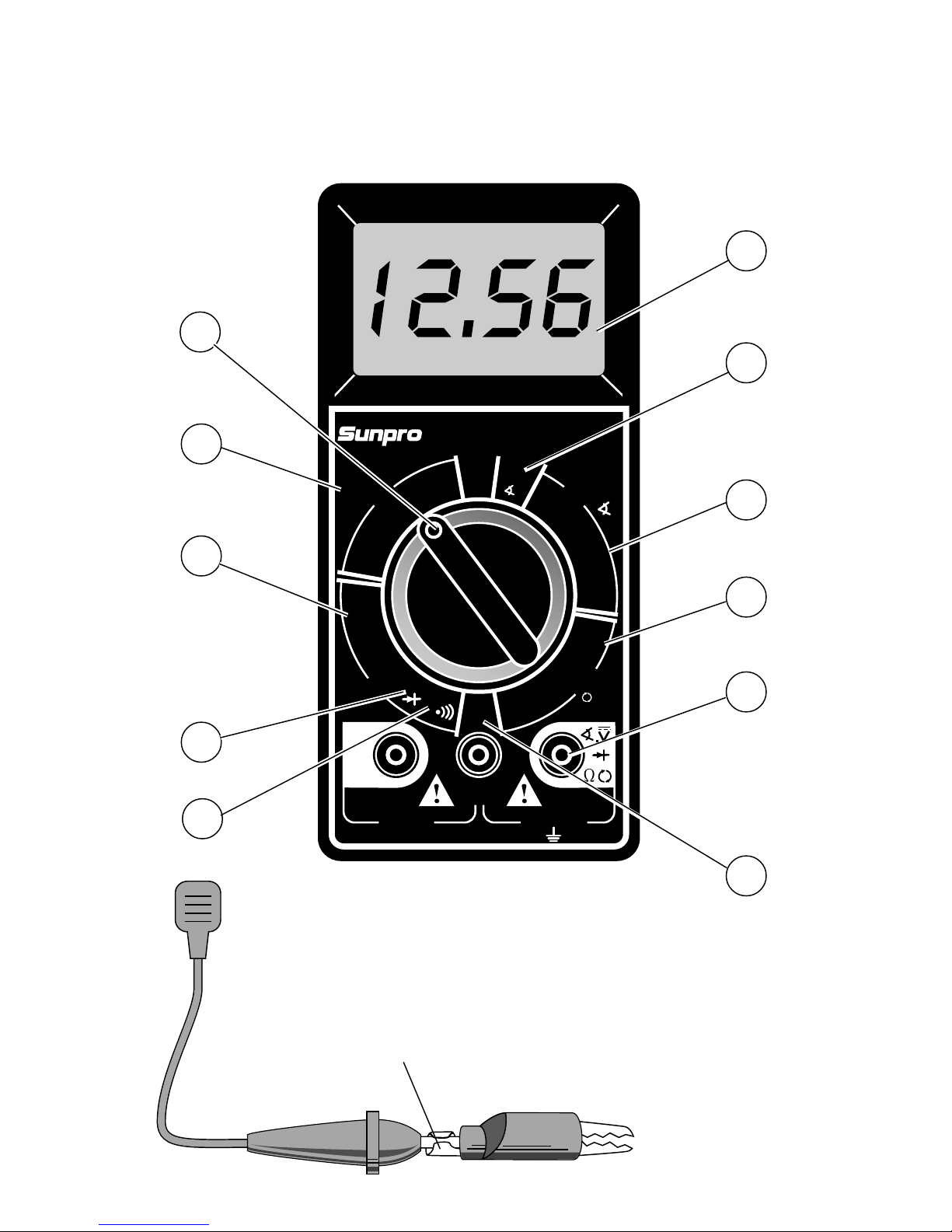
Functions and Display Definitions
1. ROTARY SWITCH
Switch is rotated to turn multimeter ON/
OFF and select a function.
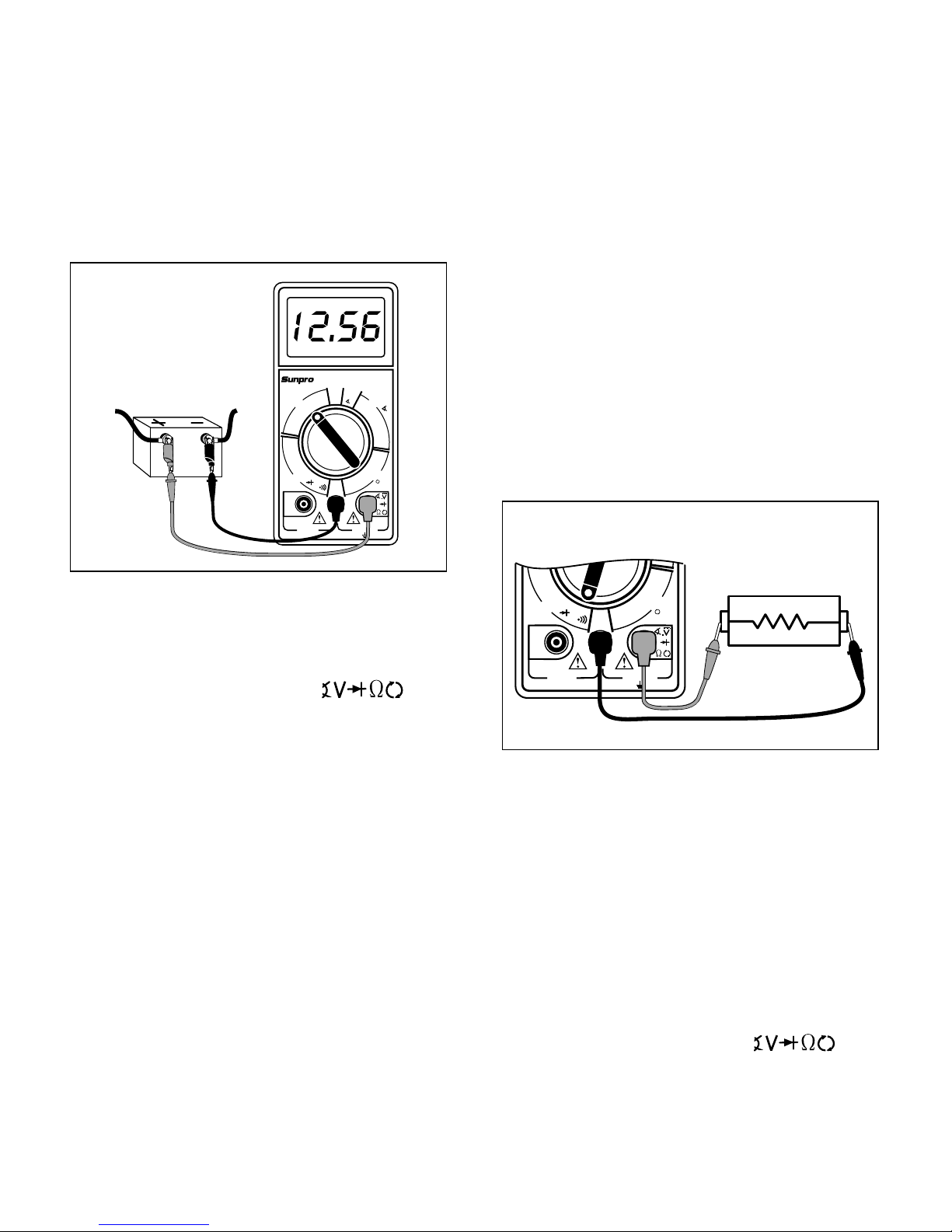
2. DC VOLTS
This function is used for measuring DC
(Direct Current) Voltages in the range of 0
to 200V.
3. OHMS
This function is used for measuring the
resistance of a component in an electrical
circuit in the range of 0.1Ωto 20MΩ. (Ωis
the electrical symbol for Ohms)
4. DIODE CHECK
This function is used to check whether a
diode is good or bad.
5. CONTINUITY TESTS
It is also used for fast continuity checks of
wires and terminals. An audible tone will
sound if a wire and terminal are good.
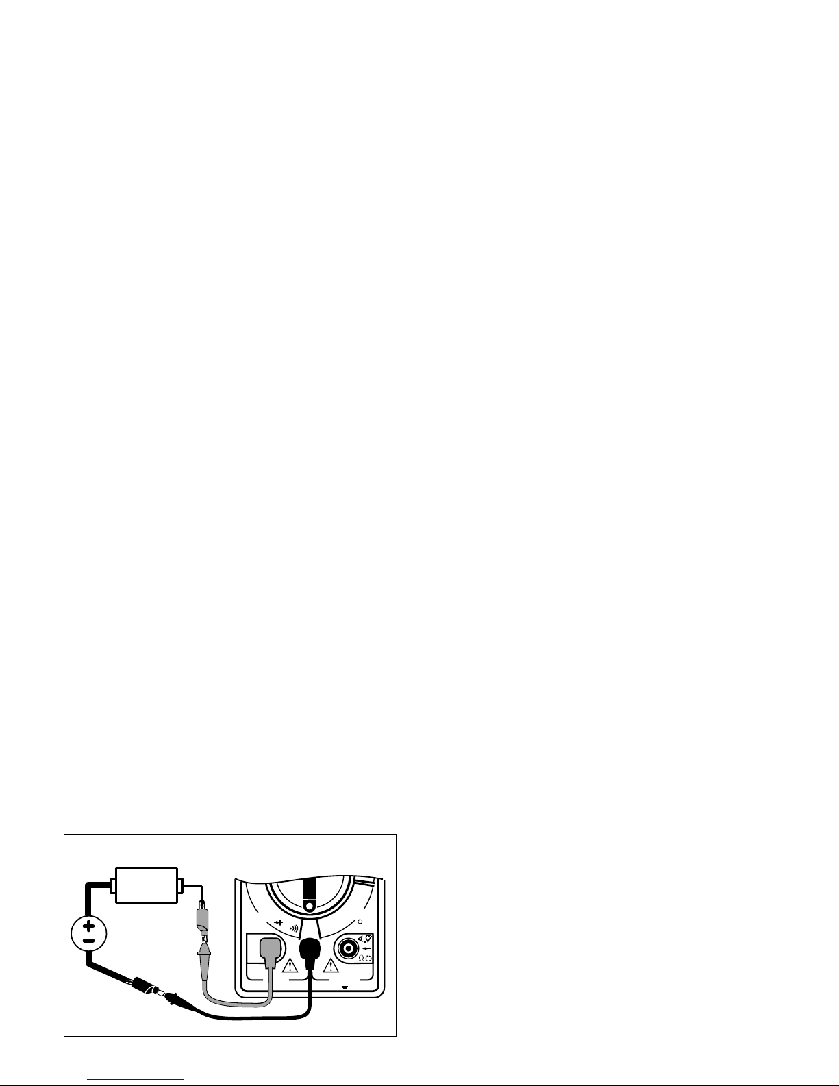
6. DC AMPS
This function is used for measuring DC
(Direct Current) Amps in the range of 0 to
15A.
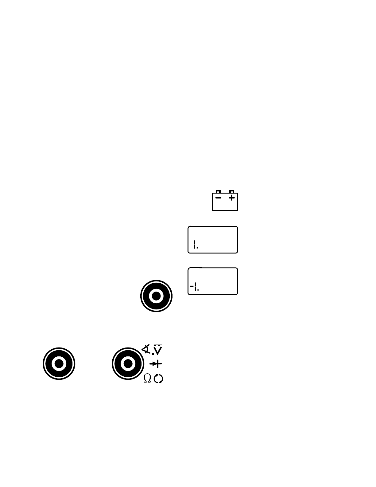
7. TEST LEAD JACKS
BLACK Test Lead is always
inserted in the COM jack.
RED Test Lead is inserted in
the jack corresponding to the
multimeter rotary switch set-
ting.
8. TACH
Thisfunctionisusedformeasuringengine
speed (RPM).
9. DWELL
ThisfunctionisusedformeasuringDWELL
on distributor ignition systems, and sole-
noids.
10.DUTY CYCLE
This function is used for measuring DUTY
CYCLE on relays, solenoids, and other
ON/OFF types of devices.
11.DISPLAY
Used to display all measurements and
multimeter information.
Low Battery – If this symbol
appears in the lower left corner
of the display, then replace the
internal 9V battery. (See Fuse
and Battery replacement on
page 7.)
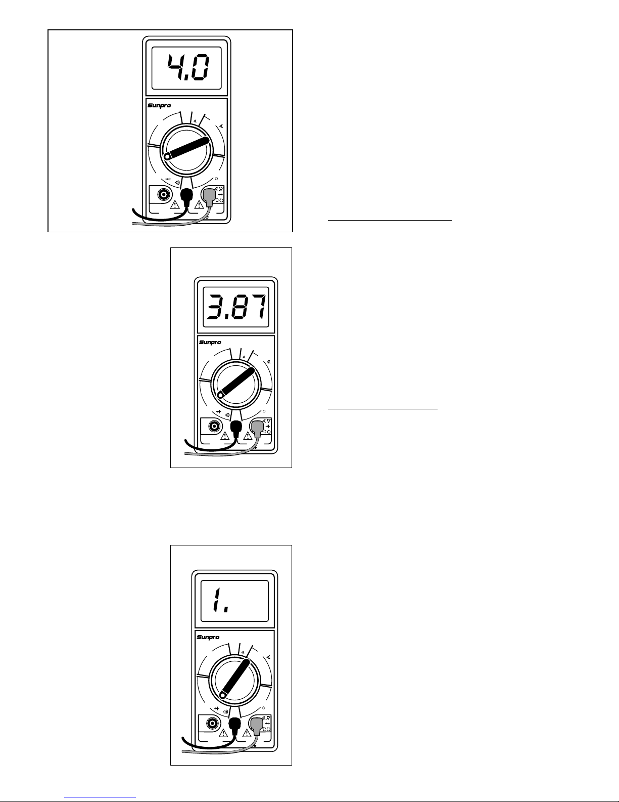
Overrange Indication – If “1”
or “-1” appears on the left side
of the display, then the multim-
eter is set to a range that is too
small for the present measure-
ment being taken. Increase the
range until this disappears. If it
does not disappear after all the
ranges for a particular function have been
tried,thenthevaluebeingmeasuredistoo
large for the multimeter to measure. (See
Setting the Range on page 6.)
Automatic Power Off
Themultimeterwillautomaticallyturnitselfoff
after approximately thirty (30) minutes if the
rotary switch has not been rotated. Momen-
tarily change the rotary switch position to
restore normal operation.
Zero Adjustment
The multimeter will automatically zero on the
Volts, Amps and RPM functions.
Automatic Polarity Sensing
The multimeter display will show a minus (-)
sign on the DC Volts and DC Amps functions
when test lead hook-up is reversed.
5
Always connect TEST LEADS to the multi-
meter before connecting them to the cir-
cuit under test!!
COM
DC VOLTS
OHMS
DIODES
CONTINUITY
15
A
TACH
DWELL
DUTY CYCLE
DC AMPS