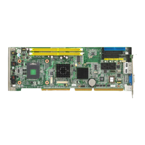
aculab Prosody X PCI Express R1 Card User manual

Prosody X PCI Express R1 Card
Installation guide
MAN1490 Revision 1.4

Prosody X PCI Express R1 Card – Installation Guide
2 of 41
PROPRIETARY INFORMATION
The information contained in this document is the property of Aculab plc and may be the
subject of patents pending or granted, and must not be copied or disclosed without prior
written permission. It should not be used for commercial purposes without prior agreement in
writing.
All trademarks recognised and acknowledged.
Aculab plc endeavours to ensure that the information in this document is correct and fairly
stated but does not accept liability for any error or omission.
The development of Aculab’s products and services is continuous and published information
may not be up to date. It is important to check the current position with Aculab plc.
Copyright © Aculab plc. 2004-2010 all rights reserved.
Document Revision
Rev Date By Detail
1.0.0 DJL Initial Release
1.0.1 12/02/07 DS Update including provisional power figures
1.0.2 28/02/07 DS Update after team review
1.0.3 6-Mar-07 CJB Updated prior to RDR
1.0.4 12-Apr-07 CJB Minor corrections and formatting
1.0.5 16-Apr-07 CJB Update following review – release candidate
1.0.6 24-Aug-07 CJB Minor review changes – RJ45 location diagram added
1.1 21 Sep-09 CJB Re-formatted, 75 Ohm connection updated
1.2 07-Oct-11 CJB/
EBJ Minor corrections and Declaration of Conformity
added.
1.3 08-Jan-13 EBJ Updated Declaration of Conformity
1.4 09-May-13 EBJ Jumper identification updated

Prosody X PCI Express R1 Card – Installation Guide
CONTENTS
1Introduction............................................................................................................................. 5
1.1 General..........................................................................................................................................5
1.2 Uses of the Prosody X PCI Express card...................................................................................7
1.3 Call control ...................................................................................................................................8
1.4 Media processing functions........................................................................................................8
1.4.1 Playback and recording of speech data................................................... 8
1.4.2 Tone generation and detection................................................................ 9
1.4.3 Matrix conferencing with echo suppression and noise gating..................9
1.5 Speech and data paths................................................................................................................9
1.6 Network Connection ....................................................................................................................9
1.6.1 External connector locations.................................................................. 10
1.6.2 External connector pinouts ....................................................................11
1.6.3 RJ45 crossover connection for E1/T1 interface..................................... 11
1.6.4 75 ohm trunk connection........................................................................11
1.6.5 Dual LAN connection............................................................................. 12
1.6.6 Cable lengths......................................................................................... 14
1.7 H.100 CT expansion bus interface............................................................................................14
1.7.1 14
1.7.2 H.100 bus loading.................................................................................. 15
1.8 Host system recommendations................................................................................................15
2Card Installation.................................................................................................................... 16
2.1 Installing the Card......................................................................................................................16
2.1.1 Installing a card into a host:................................................................... 16
2.2 Configuring the Prosody X PCI Express card IP addresses..................................................17
2.2.1 Prosody X host NIC IP address – Windows example............................ 17
2.2.2 Prosody X networked computer IP address........................................... 17
2.3 Prosody X PCI Express card LED usage .................................................................................18
2.3.1 Media processing DSP LEDs.................................................................18
2.3.2 Ethernet interface LEDs......................................................................... 19
2.3.3 Host Ethernet interface LEDs ................................................................19
2.3.4 Firmware controlled LEDs......................................................................19
2.3.5 CAS/SS7 signalling DSP module LEDs................................................. 20
3Approval information ........................................................................................................... 21
3.1 Safety warnings..........................................................................................................................21
3.2 EMC compliance ........................................................................................................................22
3.3 Approval details.........................................................................................................................22
3.4 Usage and type...........................................................................................................................22
3.5 Network timing...........................................................................................................................22
3.6 Approved functionality..............................................................................................................22
3.7 Regulatory Warnings.................................................................................................................22
3.8 Approval label ............................................................................................................................23
3.9 Documentation release..............................................................................................................23
3.10 Software release.........................................................................................................................23
3.11 User Responsibilities.................................................................................................................23
3.12 Speech calls ...............................................................................................................................24
Appendix A: Country specific information.............................................................................. 25
Appendix B: USA/Canada approval details............................................................................. 26
Appendix C: Approval details for UK and other EU countries............................................... 31
Appendix D: Approval details for Australia............................................................................. 36 3 of 41

Prosody X PCI Express R1 Card – Installation Guide
Appendix E: Technical specifications......................................................................................38
Appendix F: Ferrite clamp fitting instructions.........................................................................41
4 of 41

Prosody X PCI Express R1 Card – Installation Guide
1Introduction
1.1 General
This document is the installation and user guide for the Aculab Prosody X PCI
Express card. This document covers all variants of this card.
The Prosody X PCI Express card includes options for media processing resources
(DSPs) and up to four E1/T1 interfaces. There is also an optional signalling DSP
module which may be required to support some E1 or T1 protocols. The module
includes up to two signalling DSPs, which will enable the card to process CAS and
SS7 signalling protocols. Refer to the ‘Aculab Call, Switch & Speech Driver
Installation Guide’ for further information on using and configuring signalling DSP
resources.
The Prosody X PCI Express card provides an interface between a telephone network,
an Ethernet network, a PCI Express bus (including host storage devices), and a
standard H.100 TDM expansion bus. The Prosody X PCI Express card contains a
digital switch matrix that allows arbitrarily switched interconnection between:
•4096 speech paths on the PCI Express card H.100 CT bus
•1 or 2 media DSPs, on the PCI Express card, for Prosody speech & IP telephony
processing
•Telephone trunk connections via up to four E1/T1 interfaces
•CAS & SS7 signalling DSP connections (when optional module is fitted)
•IP Telephony connections via a dual Ethernet interface
CAS/SS7 signalling DSP
J13
J20
J19
J18
H100 Bus
Controller
H.100 bus termination LED.
J8
ProsodyX PCIe card
5 of 41

Prosody X PCI Express R1 Card – Installation Guide
The Aculab Prosody X PCI Express card shown with the optional signalling DSP
Module
NOTE
The Prosody X card is controlled by Ethernet protocols (e.g. TCP, UDP)
connected through an on-card card Media Access Controller or dual Ethernet
interface (see section 2.2).
This product is referred to as the 'Prosody X PCI Express card’ in this document
unless the context requires a more specific term.
Prosody X PCI Express card jumpers
With the exception of jumper J13, all jumpers are for factory use and should not be
fitted. J13 controls the flash image source on boot-up for the on-board PowerPC;
boot-up is normal unless the jumper is fitted:
J13 fitted – on-board PPC will boot from backup flash image
For further details of the flash programming functions, please contact Aculab support.
The serial number of the Prosody X PCI Express card is used when configuring the
Aculab libraries to uniquely identify a Prosody X PCI Express card in the system. The
serial number of the card is located on the reverse of the card on the top edge and
has the format: P/N ACXXXX S/N XXXXXX WONXXX
The four digits following P/N AC denote the Aculab part number and identify card type
during driver installation. The six digits following S/N are used to uniquely identify a
card during driver configuration. The remaining digits are for Aculab use.
Installation
The card installation & connection sections refer to installation of the Prosody X PCI
Express card into a host computer, subsequent connection to the network, and
provide hardware control and configuration information.
Approvals
The approval information section, in conjunction with the country-specific appendices,
gives the conditions of the Approval for connection to the telephone network,
requirements for installation and safety, and other regulatory matters. This section
and the appropriate country-specific appendix contain statements regarding use of
the Prosody X PCI Express card that are legal requirements for connection to the
public network. Failure to use the Prosody X PCI Express cards in accordance with
any of these instructions for use may invalidate the approval for connection.
The approval information in section 3 provides general approvals information. To fully
appreciate the conditions of approval for connection to the telephone network, it is
important that the appropriate country-specific appendices are read in conjunction
with the other sections of this document.
Usability statement
Speech and data processing, call control and digital switch control functions are
provided via one of several Aculab libraries that are described in separate
publications specific to those topics. The card is not a complete telephony system,
and only has usable functionality when associated with a host system which is
running application software using the Aculab API.
6 of 41

Prosody X PCI Express R1 Card – Installation Guide
NOTE
These instructions for use assume that the various elements are being
assembled and integrated into a system by someone competent in such matters
and do not constitute an alternative for such competence.
1.2 Uses of the Prosody X PCI Express card
The Prosody X PCI Express card is a plug-in card suitable for use in many different
types of PCI Express compatible computers. It provides a platform in which to carry
out a range of functions.
Computer Telephony Bus
The H.100 (CT bus) expansion interface enables connectivity within the same chassis
between various kinds of H.100 compatible PCI Express or PCI based speech and
data products from different vendors. This provides scalability within a host system.
Integration
The Prosody X PCI Express card is a highly integrated Computer Telephony
component. By combining TDM and IP digital access, and the media processing
capabilities of Prosody, Aculab has produced a high capacity, scaleable single slot
CT component.
Switching
The Prosody X PCI Express card contains a digital switch matrix that allows arbitrarily
switched interconnection between up to 120 channels on an E1-network, up to 92
channels on a T1-network and up to 4096 speech paths (timeslots or channels) on
the H.100 CT expansion bus. The H.100 CT expansion bus supports connection to
other H.100 compliant devices.
Control
The Prosody X PCI Express card is always controlled via a Media Access Controller
(MAC) and its associated device driver. The user can choose to control the card via
an on-board host MAC which is accessed over the PCI Express bus, or any off-board
MAC either in the same host system or a separate host system. This provides
flexibility in system design as the card does not have to be installed in the same
system as the host that runs the application software. This in turn can provide
scalability outside of the host system, if the application requires a distributed
architecture. Note that in this case the control traffic will share an Ethernet interface
with any VoIP traffic passing through the card.
If the host MAC on the Prosody X PCI Express card is used then the device driver is
supplied by Aculab. If connection is via a regular Network Interface Card (NIC) or
integral to a motherboard then the device driver is simply the one already in use for
that product. Aculab provides libraries and associated device drivers for a range of
operating systems. Please contact Aculab for information on availability.
External Ethernet Connector
The Prosody X PCI Express card may be connected to a standard 100BaseT
Ethernet LAN, allowing various functions including media processing for IP Telephony
and control of the card from a remote host.
7 of 41

Prosody X PCI Express R1 Card – Installation Guide
Media Rich DSPs
The card has up to 2 media DSPs fitted which allow the processing of and conversion
between IP and TDM based media streams.
1.3 Call control
The call control interface is at a low level (in signalling terms), and provides maximum
information and control over the various stages of call progress, (set-up, acceptance,
clearing, etc). This interface is accessed via a device driver that has been prepared
for the operating system in use.
The call processor checks each outgoing message provided by the application
program for syntax, validity of content and context. If errors are found, the call can be
automatically cleared. In these instances the software can form an effective barrier
between the application program and the telephone network, protecting the network
from invalid call signalling.
Several elements of call signalling related information are available to the application
program, although in some cases this depends upon provision of call specific
information by the Public Switched Telephone or Ethernet networks. One such
information element is the number used by the caller on calling into the card, (the DDI
number). This is only available when the service obtained from the PSTN is of the
appropriate type. Another information element which may be available, is Calling Line
Identity (CLI). On incoming calls, CLI makes the telephone number of the calling party
available to the application program.
Full details on the control of calls using the Prosody X PCI Express card are available
in a separate publication ‘Aculab Call Control API Guide’, which can be
downloaded from the support area of the Aculab company web site at
www.aculab.com
1.4 Media processing functions
The Prosody X PCI Express card is designed for processing digitised speech data,
with support for recording/playback, echo cancellation, conferencing, DTMF, and call
progress tones and more. This functionality is available when one or more media
DSPs are present.
Further details are available in the Aculab TiNG API guides and Application Notes.
Speech or data is transferred in either direction between any of the following:
•The host storage medium
•Any of the channels on the H.100 CT expansion bus or the E1/T1 trunk
connections
•Any RTP endpoints on the Ethernet connection in use
The media processing DSPs on the Prosody X PCI Express card can provide various
processing functions on the data including:
1.4.1 Playback and recording of speech data
•Compression and decompression between the H.100 64kb/s speech data and
the host computer hard drive. Please consult www.aculab.com for a list of
supported algorithms.
•Pitch invariant fast and slow replay (50 to 200%) at all data rates
•Trimmed recording to eliminate periods of silence at all data rates
8 of 41

Prosody X PCI Express R1 Card – Installation Guide
•Echo cancellation
1.4.2 Tone generation and detection
•DTMF detection
•Call progress tone recognition
•Universal tone generation and recognition (user programmable)
•Fax support
1.4.3 Matrix conferencing with echo suppression and noise gating
•Matrix conferencing
•Many to one conferencing and one to many broadcasting
•Speaker tracking
•Gain control and noise/tone suppression of conference inputs
•Echo cancellation
1.5 Speech and data paths
Speech or data associated with telephone calls may be switched without modification
to other cards or on-board modules (DSPs) for processing, for example, speech
processing can be performed on the card by the media processing DSPs.
The card maintains bit integrity within timeslots between TDM interfaces on the card
and also via the H.100 expansion interface.
There are various types of multi-channel path provided by the card, as follows:-
1. E1 trunks –2.048Mbit systems or ISDN
T1 trunks - 1.554Mbit T1 systems or T1 PRI
2. RTP Voice over IP Ethernet interface
3. Host storage via the PCI Express bus – bi-directional for record and playback,
channel count is dependent on compression and host capabilities
4. The H.100 CT expansion bus
Any one 'source' of speech or data may be distributed to a number of separate 'sinks',
but it is not possible via switching on the card alone for more than one source to feed
a single sink. This conferencing function is sometimes required to combine separate
speech sources and can be performed on board with the use of the on-board media
DSP resources.
Full details on the switching of calls using the Prosody X PCI Express card are
available in a separate publication ‘Aculab Switch Control API Guide’ which can be
downloaded from the support area of the Aculab company web site at
www.aculab.com.
1.6 Network Connection
The Prosody X PCI Express card connects to either E1/T1 digital telephony networks
or Ethernet LAN or both, depending on the application. Each E1/T1 trunk connection
is software configurable for either E1 or T1 operation.
9 of 41

Prosody X PCI Express R1 Card – Installation Guide
An E1 interface connects to the 2.048 Mbit/s digital system or Primary Rate
Integrated Services Digital Network (ISDN). Network attachment is via a service
provision often used to connect digital PBXs to the telephone network (NT1). Each E1
interface may make or receive up to 30 separate calls at a time, or may carry 31
channels without signalling.
A T1 interface connects to the 1.544Mbit digital system via a Channel Service Unit
(FCC, IC or UL Listed CSU). Each T1 trunk may carry 23 channels when PRI (ISDN)
protocols are used, or 24 when CAS (robbed bit) protocol is used.
The LAN interface connects IP telephony (VoIP) channels up to the capacity of the
card and so a single connection will typically carry more channels than an E1 or T1
trunk. The LAN interface may also carry host application control and status traffic at
the same time as telephony data.
NOTE
This card may contain both E1/T1 and Ethernet interfaces that use the same type
of connector. It is important to understand the different cabling requirements for
E1/T1 and Ethernet circuits when installing cables that may look almost identical
in appearance. It is good practice to use cable identification labeling or colour
coding to differentiate between cable types.
Ample strain relief should be fitted when installing all network cables. Any damage
caused by inadequate strain relief to cards will not be covered by your warranty.
Both E1/T1 and Ethernet cables may be connected and disconnected while the card
is installed and active.
Bear in mind that disconnecting an active E1/T1 trunk will cause an alarm condition
both within the host system while the application software is running and at the
corresponding network end of the cable. You may wish to check with the local
network operator if there is a requirement for advance notification of E1/T1 trunk
installation and maintenance.
1.6.1 External connector locations
There are up to five external connectors available depending on the product variant. It
is important to identify these correctly during installation as there is no compatibility
between E1/T1 trunk interfaces and LAN interfaces. Part populated trunk variants will
always have trunk 0 as the first available E1/T1 connection.
10 of 41

Prosody X PCI Express R1 Card – Installation Guide
1.6.2 External connector pinouts
NOTE
The modular sockets provided for Ethernet and E1/T1 connections to network
equipment are commonly referred to as “RJ45” types. This terminology is used in
this document and refers to a non-keyed 8 position, 8 circuit (8P8C) modular
socket. For T1, the connectors are compatible with RJ48C jacks.
The front plate of the PCI Express card has up to 5 RJ45 sockets. The first socket
(bottom) is a dual Ethernet interface. The remaining four sockets, numbering bottom
to top, are E1/T1 telephony network trunk connections. The E1/T1 pin outs are as
detailed below:
RJ45 plug Circuit RJ45 pin
1 RX A tip 1
2 RX A ring 2
3
4 TX A tip 4
5 TX A ring 5
6
7
8
Shield ------------- Shield
CAUTION
When making a network connection, to reduce the risk of fire, only
telecommunications line cord of 26 AWG or larger may be used.
1.6.3 RJ45 crossover connection for E1/T1 interface
A 'cross-over' cable is required to connect two E1 or T1 interfaces 'back-to-back', for
example, when one interface is to run as an exchange end emulation and the other
interface a user end application. The cable should be wired as follows.
User End Exchange End
4 to 1
5 to 2
1 to 4
2 to 5
1.6.4 75 ohm trunk connection
NOTE
Different E1 impedance can be supported on the same card;
The card can simultaneously support both E1 and T1 ports.
11 of 41

Prosody X PCI Express R1 Card – Installation Guide
Some legacy E1 PSTN networks require 75 Ohm trunk connection. The default
impedance for E1 protocols is 120 Ohm. It is important to confirm with the network
operator which impedance the PSTN is using during the installation process, as a
mismatch can lead to signal degradation and erratic equipment behaviour that is
difficult to diagnose later.
The following signalling services may be expected to be configured for 75 Ohm in
legacy switching equipment which provides the following protocols:
DASS2
DPNSS
SS7/ISUP
All E1 CAS protocols
Each 75 Ohm trunk is normally connected via a pair of coaxial cables with BNC
connectors. A Balun is available to convert between RJ45 and co-axial cabling. The
Balun also converts between 120 and 75 Ohm interfaces, so the trunk does not need
to be configured for 75 Ohm operation when this type of converter is used.
These are available from Aculab, and provide a pair of BNC connectors labelled as
RX and TX for each E1 trunk.
It is important to use 75 Ohm BNC cable when connecting to legacy BNC equipment.
For installation convenience, the BALUN converter may be located at either end of
the interconnection, so for example it may be convenient to use available RJ45 patch
panels to connect the trunk and locate the BNC converter adjacent to the legacy
equipment.
1.6.5 Dual LAN connection
The LAN connector is located closest to the PCIe expansion interface. This provides
two Ethernet network connections. One has the conventional pin assignment and the
second requires an adapter cable to provide the second connector with normal pin
assignment.
The LAN interfaces are designed to operate at Fast Ethernet (100Base-T) data rates.
If connected to network equipment that is not Fast Ethernet capable, the interface will
attempt to negotiate a 10Base-T link speed. In most cases this will impose an
artificially low channel count on VoIP connections that will limit the host system
capacity.
The LAN interfaces are not designed to be connected to legacy “hub” (half duplex)
network equipment.
12 of 41

Prosody X PCI Express R1 Card – Installation Guide
Pin out of the dual Ethernet plug to two Ethernet sockets (T568A):
Dual
Ethernet
Aculab card faceplate
E1/T1
RJ45
socket
Aculab card
Ethernet
RJ45
socket
100 BASE-T
8 7 6 5 4
(FA-679)
3 2 1
6 3 2 1 6 3 2 1
Red - port 0
Blue - port 1
Ethernet adapter cable, RJ45 plug to 2 x RJ45 sockets
RJ45 plug circuit RJ45 interface 0 RJ45 interface 1
1 TX A 1
2 TX A 2
3 RX A 3
4 TX B 1
5 TX B 2
6 RX A 6
7 RX B 3
8 RX B 6
Shield ------- Shield Shield
NOTE
When connecting the Aculab card Ethernet interface to a 10/100BaseT Ethernet
network, the Ethernet adapter should be used.
NOTE
The 10/100BaseT interfaces should only be connected to an Ethernet switch.
CAUTION
Do not connect directly between the LAN interface and a Gigabit Ethernet switch
– always use the adapter supplied.
Cat 5 cabling is recommended for 100Base-T Ethernet connections. Higher
specification cabling such as Cat 5e, 6 or 6e may also be used.
13 of 41

Prosody X PCI Express R1 Card – Installation Guide
1.6.6 Cable lengths
Cat 5/6 cabling is designed for an overall span length of 100m. It is recommended
that the cumulative length of multiple cables which may be connected via a patch
panel does not exceed 100m, so the recommended maximum single cable length is
90m to allow for 10m of patch connections. For span lengths approaching the 100m
limit it is important to specify and install high quality cables.
For E1 trunks converted to BNC cabling, it is recommended that overall span length
is limited to 100m maximum and that 75 ohm cabling and connectors are used. The
75 ohm adapter should be installed close to the Prosody X RJ45 (RJ48C) socket to
minimise impedance mismatch effects.
Span lengths in excess of 100m may continue to operate, in this case the installer
should check that there is adequate margin on signal levels to maintain expected
service levels.
1.7 H.100 CT expansion bus interface
The Prosody X PCI Express card can occupy any position in a ‘chain’ of H.100 CT
Bus devices interconnected with a suitable ribbon cable.
NOTE
The H.100 expansion bus is provided for connections between H.100 capable
equipment within a single host chassis. It is not designed to be used for inter-
chassis connections.
The H.100 CT bus ribbon cable may consist of no more than 20 connectors, with a
typical distance between each connector of one inch, and a maximum bus cable
length of 20 inches (including connector terminations).
In addition, in order to assure that the interleaved grounds on the ribbon cable act as
effective grounds, the distance between populated CT bus cards should be as short
as possible and MUST BE less than 7 inches. It is also recommended that the ribbon
cable be no longer than required to interconnect the chain of H.100 CT bus devices.
NOTE
It is bad practice to leave a “spare” length of ribbon cable unconnected beyond
the terminating card, as this will compromise the electrical termination and
degrade the signal quality. In severe cases data integrity will be impaired.
If the Prosody X PCI Express card is the first or last device at either end of a ribbon
cable, then the card must be placed in terminated bus mode.
Cards are terminated via the ACT configuration utility or alternatively by setting the -ht
(H.100 bus mode) switch in the device driver. See the ‘Aculab Call, Switch &
Speech Driver Installation Guide’. A single orange LED will turn on when the card
is configured for H.100 termination.
NOTE
The Prosody X PCIe card may be configured as H.100 clock master. There may
be just one active clock master at any time. It is good practice to configure a card
at one end of the H.100 ribbon cable as the normal clock master to provide the
slave cards with the highest quality clock and frame synchronization signals.
14 of 41

Prosody X PCI Express R1 Card – Installation Guide
1.7.1 H.100 bus loading
Prosody X PCI Express cards have a loading factor of one on the H.100 CT bus. The
maximum loading allowed on the H.100 CT bus is 20. The total loading is calculated
by adding the loading factor of all the devices on a single H.100 ribbon cable. The
electrical loading limit of H.100 means that theoretically, 20 Prosody X PCI Express
cards can be used in the same host. H.100 channel capacity will normally restrict the
theoretical loading to a maximum of 16 Prosody X PCI Express cards in the same
host, for non-blocking E1 switching. Individual system constraints may reduce this
further.
1.8 Host system recommendations
Expansion slots
The card may be installed in any PCI Express expansion slot with x4 or greater slot
size which is also able to accommodate the full length and full height form factor. For
example, the card may be installed in a x16 PCI Express expansion slot, as the PCIe
bus protocol will automatically fall back to use the x1 connection available on the
Prosody X product.
The product is not compatible with expansion slots that provide x1 edge connectors.
Forced air cooling
CAUTION
In most instances, forced-air-cooling is an essential requirement of a host
system. Operation of the Prosody X PCI Express card without adequate cooling
will reduce the reliability of operation and seriously affect the lifetime of the
product.
The Prosody X PCI Express card incorporates on board temperature monitors that
enable the cooling system to be regulated to maintain acceptable operating
temperatures. The operating limits for these temperatures are given in the
Environmental section. (Appendix E).
15 of 41

Prosody X PCI Express R1 Card – Installation Guide
2Card Installation
CAUTION
Observe electrostatic discharge precautions when handling PCI Express
expansion products. Do not touch the gold plated connectors while installing a
card.
2.1 Installing the Card
The installation procedure for expansion cards will vary from one type of host
computer to another, and the exact details of the installation procedures for
expansion cards must be sought in the user guide supplied by the host computer
manufacturer. However, in general:
•Do not attempt to install or remove the Prosody X PCI Express card unless the
mains power supply is completely removed from the host computer and all
network cables are disconnected from the network.
•To ensure safety, any covers removed from the host computer in order to install
the Prosody X PCI Express card must be replaced before the mains power
supply is reconnected.
•Do not connect the Prosody X PCI Express card to a 2.048/1.554 Mbit/s digital
service or Primary Rate ISDN network until this document, and in particular the
sections marked 'Installation and Safety', have been read in full and understood.
•Normal ESD (electrostatic discharge) precautions should be followed while the
card is being handled
2.1.1 Installing a card into a host:
1. Remove the power and disconnect any mains leads
2. Remove the host computer covers.
3. Locate a vacant full-length PCI Express slot with a motherboard connector of x4
lanes or greater and, if required, remove the blanking plate.
4. Fit the card to the PCI Express slot and screw the metal bracket to the chassis.
5. Ensure that adjacent devices/cards can not make contact with the Prosody X
card or signalling DSP module.
6. Fit H.100 CT bus ribbon cables between the Prosody X PCI Express card
connectors and any other cards that are required.
7. Replace the covers on the host computer.
8. Attach the mains leads and apply power.
Having completed installation of a new card, if you have not already done so, you will
now need to download and install the required drivers. Please refer to the Aculab
Installation Tool (AIT) documentation for downloading the Aculab software
(including drivers, firmware and utilities), and the Aculab call, switch and speech
driver installation guide (ACT) for driver and protocol firmware installation.
16 of 41

Prosody X PCI Express R1 Card – Installation Guide
NOTE
Revision 6.4.X or later software is required for the Prosody X PCI Express
product. It is recommended to use the current release available on the
aculab.com website.
2.2 Configuring the Prosody X PCI Express card IP addresses
The Prosody X card will be detected by the host system as a network device (NIC).
The card is a networked computer (DSPs, Power PCs, etc), an external Ethernet
connector, and a host NIC, all connected together by an Ethernet switch. Both the
NIC and the network computer require IP addresses to be configured within the same
IP subnet-numbering scheme.
2.2.1 Prosody X host NIC IP address – Windows example
For the Prosody X card to host system Ethernet connection, Windows defaults to
DHCP (obtain an IP address automatically). Should you require a static IP address,
use the standard Windows connection properties dialogs.
2.2.2 Prosody X networked computer IP address
The ACT is used to configure this IP address. The ACT is downloaded from the
Aculab web site using the Aculab Installer Tool (AIT).
For further details on using the ACT, please see the Aculab call, switch and speech
driver installation guide (1761.pdf). This document also includes details for
command line configuration of the IP addresses and firmware download to the Aculab
cards.
17 of 41

Prosody X PCI Express R1 Card – Installation Guide
2.3 Prosody X PCI Express card LED usage
There are a number of surface mount LEDs mounted on the Prosody X PCI Express
card. The LEDs are arranged as shown on the following diagram.
The specific meaning or use of each LED is often subject to the firmware and
configuration of the card and are normally for Aculab diagnostic purposes only. In
general however, flashing LEDs are an indication of activity on a device or interface.
Firmware Controlled
D6-D21
HOST LEDs
Media
DSPA
Boot Monitor
D43
-
46
DSI Monitor
D47-50 Media
DSPB
LAN I/F 1
D51-53
LAN I/F 2
D54-56
LED groups Positions Order Description
Firmware controlled D6-D21 D21 is closest to front of card
Boot Monitor D43-D46 D46 is closest to front of card
DSI Monitor D47-D50 D50 is closest to front of card
LAN I/F 1 D51-D53 D53 is closest to front of card
LAN I/F 2 D54-D56 D56 is closest to front of card
2.3.1 Media processing DSP LEDs
The behaviour of the media DSP LEDs varies depending on the media-processing
task being carried out:
Red LED – flashes when firmware is running
Green LEDs – subject to the firmware running on the DSP, these are used to
indicate DSP firmware activity, however in most instances these are not used.
18 of 41

Prosody X PCI Express R1 Card – Installation Guide
2.3.2 Ethernet interface LEDs
A set of LEDs is used to indicate the status for each Ethernet interface. Once a
connection has been made to a network, the interface LEDs will show activity, frame
clocking etc. Only one of the connections should show activity due to transmit and or
receive call traffic (numbered from right to left):
1 = Link Activity
2 = 100Mbps
3 = Link Up
2.3.3 Host Ethernet interface LEDs
The host Ethernet interface LEDs indicate the following (numbered from right to left):
1 = N/A
2 = Link Activity
3 = 100Mbps
2.3.4 Firmware controlled LEDs
Card firmware LED status
In normal operation the six LEDs D6-D11 are flashing in a “walking one” sequence.
Trunk firmware LEDs
Once initialised, LEDs D18-21 indicate E1/T1 trunk activity as follows :
D18 trunk 3
D19 trunk 2
D20 trunk 1
D21 trunk 0
Inactive trunks will have the corresponding LED turned off. After trunk initialisation
(firmware download) the LED will turn on.
With the exception of SS7 protocols, where the default behaviour is layer 1 state
monitor, during normal operation the firmware LEDs will be seen to flash to indicate
call activity.
Layer 1 state monitor
This is the default for SS7 protocols. Most other protocol firmwares can be changed
to monitor layer 1 by the use of a firmware switch; check the appropriate protocol
release notes for details of the available protocol switches.
When monitoring layer 1, the state of a trunk will be indicated by its associated LED
(LED on indicates a good layer 1. LED off indicates a bad layer 1).
19 of 41

Prosody X PCI Express R1 Card – Installation Guide
2.3.5 CAS/SS7 signalling DSP module LEDs
Each signalling DSP has three LEDs to indicate status. The green LED will remain off
until the module is taken out of a reset state. When two DSPs are present, these two
LEDs will flash alternatively to indicate the module is not in a reset state.
The remaining red and green LED pairs are under DSP software control.
DSP ’B’
LEDs
DSP ’A’
LEDs
Reset
LEDs
20 of 41
Table of contents
Other aculab PCI Card manuals
