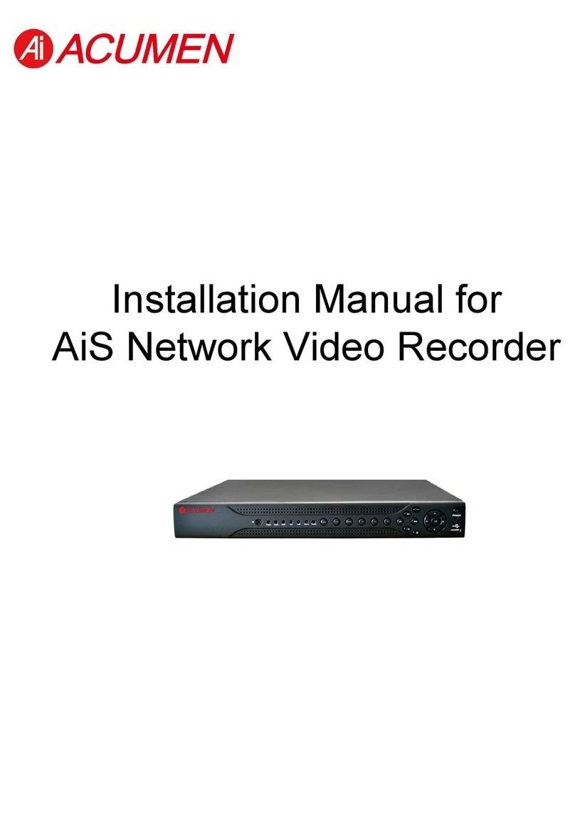
Acumen DataBridge SDR2-CF User manual

ACUMEN INSTRUMENTS CORPORATION
DataBridge™ SDR2-CF and SDR2-OEM-CF
Configuration Guide
revision 1.0 • 09/2008


Copyright
This document is copyrighted by Acumen Instruments Corporation with all rights reserved.
No part of this document may be reproduced in any form without prior written consent of
Acumen Instruments Corporation.
Copyright © 1998-2008 by Acumen Instruments Corporation. All rights reserved.
Disclaimer
This manual has been thoroughly reviewed for accuracy, and every effort has been made to
ensure that the information is accurate and complete. However, different versions of this
product have different features and capabilities, and this manual only reflects one of those
versions. Therefore, Acumen Instruments Corporation assumes no responsibility for errors,
omissions or defects in this material, and shall not be liable for any damages resulting from
their use.
The information in this document is subject to change without notice.
ACUMEN INSTRUMENTS CORPORATION MAKES NO WARRANTY OF ANY KIND WITH RESPECT TO
THIS DOCUMENT,EITHER EXPRESSED OR IMPLIED,INCLUDING WITHOUT LIMITATION ANY
IMPLIED WARRANTIES OF MERCHANTABILITY OR FITNESS FOR A PARTICULAR PURPOSE.


SDR2-CF/SDR2-OEM-CF Configuration Guide rev 1.0 Configuring the DataBridge SDR2-CF
Table of Contents
1. Getting Started ..................................................................... 5
1.1Overview................................................................................................. 5
1.2Before you start ...................................................................................... 6
1.3A quick guide to the DataBridge SDR2-CF............................................. 6
1.4Deploying the DataBridge SDR2-CF ...................................................... 8
1.4.1Connecting power to your SDR2-CF ...................................................... 8
1.4.2Connecting to the configuration port ....................................................... 8
1.4.3Communications software ...................................................................... 8
2. Configuring the DataBridge SDR2-CF................................ 11
2.1Setting date and time............................................................................ 12
2.2Configuring the data port ...................................................................... 13
2.3Specifying a filename and folder........................................................... 14
Notes about filenames ....................................................................... 14
2.4Setting recording parameters ............................................................... 15
2.5Entering messages............................................................................... 19
Setting message parameters ............................................................. 20
2.6Testing your configuration .................................................................... 22
3. Operations.......................................................................... 23
3.1Record mode ........................................................................................ 23
3.1.1Receiving data...................................................................................... 23
3.1.2Stopping recording ............................................................................... 24
3.1.3Power failure and improper shutdowns................................................. 24
3.1.4Full storage media ................................................................................ 24
3.1.5Formatting the storage media............................................................... 24
3.1.6Partitions............................................................................................... 25
3.2Configuration Port settings ................................................................... 25
3.3Lithium battery maintenance................................................................. 26
4. Configuration Menu Reference........................................... 27
4.1Main Configuration Menu...................................................................... 27
4.1.1Set Time ............................................................................................... 28
4.1.2Set Date ............................................................................................... 28
4.1.3Toggle ANSI Mode ............................................................................... 28
4.1.4Toggle Messages ................................................................................. 28
4.1.5Enter Serial Passthrough Mode............................................................ 29
4.1.6Configure Data Port for Attached Device.............................................. 29
4.1.7Start/Stop Recording ............................................................................29
4.2Edit Messages menu ............................................................................ 30
4.3Recording Parameters menu................................................................ 31
4.3.1Change current filename ...................................................................... 32
4.3.2Toggle overwrite-oldest mode .............................................................. 32
4.3.3Toggle append mode............................................................................ 32
4.3.4Set scheduled file close parameters..................................................... 33
4.3.5Time stamp incoming lines ................................................................... 35
4.3.6Power up in passthrough mode ............................................................ 37
4.4File System Functions menu ................................................................ 37
4.4.1Display root directory ............................................................................ 38
4.4.2Select file .............................................................................................. 38
4.4.3Change current directory ...................................................................... 38

Configuring the DataBridge SDR2-CF SDR2-CF/SDR2-OEM-CF Configuration Guide rev 1.0
4.4.4Delete current file ................................................................................. 38
4.4.5Rename current file .............................................................................. 39
4.4.6Download directory via Ymodem batch ................................................ 39
4.4.7Download file as ASCII text .................................................................. 41
5. J4 Remote Control Port ...................................................... 45
5.1Overview .............................................................................................. 45
5.2Location................................................................................................ 45
5.3Functions.............................................................................................. 45
5.4Pinout and Mating Cable ...................................................................... 46
5.5Force-Record Shunt Installation ........................................................... 47
6. Service and Support ........................................................... 49
6.1Exception Codes .................................................................................. 49
Exception 2: Root Directory Full ........................................................ 49
Exception 3: Disk Full ........................................................................ 49
Exception 4: Bad Boot Record .......................................................... 49
Exception 5: Hardware Error ............................................................. 50
Exception 6: EEPROM Error ............................................................. 50
Exception 7: Cache Error .................................................................. 50
Exception 8: Buffer Error (firmware error).......................................... 50
Exception 9: Tasking Error (firmware error)....................................... 50
Exception 10: ATA/CompactFlash Error............................................ 50
Exception 11: Directory Creation Error .............................................. 50
Exception 12: FAT12 File System Detected ...................................... 50
Exception 13: FAT32 File System Detected ...................................... 50
6.2Contacting Acumen Instruments Corporation....................................... 51
6.2.1Technical support ................................................................................. 51
6.2.2U.S. Mail............................................................................................... 51
6.2.3E-mail ................................................................................................... 51
6.2.4World Wide Web .................................................................................. 51
6.3Returning Equipment............................................................................ 51
6.4Warranty............................................................................................... 52
6.4.1One year warranty................................................................................ 52
6.4.2Exclusions ............................................................................................ 52
6.4.3Limitations ............................................................................................ 52
A. Serial Port Basics ............................................................... 53
A.1Serial specifications.............................................................................. 53
A.2Data rates............................................................................................. 53
A.2.1Data rates and the UART ..................................................................... 54
A.3More asynchronous serial parameters ................................................. 54
A.3.2DTE and DCE ...................................................................................... 55
A.3.3Handshaking ........................................................................................ 56
A.3.4Voltage levels....................................................................................... 56
B. SDR2-CF and SDR2-OEM-CF Specifications .................... 59
B.1Electrical specifications ........................................................................ 59
B.1.5J7 rear power receptacle pin configuration........................................... 59
B.1.6J1 power receptacle pin configuration .................................................. 60
B.2Serial communications ......................................................................... 60
B.3CompactFlash socket........................................................................... 60
B.4Mechanical Specifications .................................................................... 60

SDR2-CF/SDR2-OEM-CF Configuration Guide rev 1.0 Configuring the DataBridge SDR2-CF
5
NOTE: The data
source is a device that
transmits serial data
for use by a computer,
printer, or data logger.
1
1
1. Getting Started
1.1 Overview
DataBridge SDR2-CF serial data recorders record RS-232 serial data to
industry-standard mass storage using an MS-DOS™/Windows™-compatible
FAT file format. The SDR2-CF (and SDR2-OEM-CF) is an SDR2-CF
equipped with a Type I or II CompactFlash (CF) socket and is designed for
use with CompactFlash storage media.
The SDR2-CF is equipped with two serial ports. With terminal software on a
PC, you can use the configuration port to manage files, set up and
communicate with the data port, set date and time, modify output messages,
download data, manipulate the storage media, and enter record and stop
modes. While recording, you can also monitor recording using the
configuration port.
During Record mode, the data port accepts RS-232C serial data from your
data source. For data sources that require initialization or querying, the
SDR2-CF can store and transmit up to eight user-defined messages. Each
message is independent and can be sent when recording starts, when
recording stops, or periodically at specific time intervals.

Configuring the DataBridge SDR2-CF SDR2-CF/SDR2-OEM-CF Configuration Guide rev 1.0
6
Both SDR2-CF ports support baud rates up to 230,400 bps and RTS/CTS
hardware handshaking for reliable high-speed communication. Your SDR2-
CF is also equipped with a real-time clock, power-saving features, non-
volatile memory, and a resume-on-power failure feature. The SDR2-CF
features a one-button front panel user interface that starts and stops
recording.
1.2 Before you start
Before you start, be sure you have the following items available:
•DataBridge SDR2-CF or SDR2-OEM-CF board
•A 5VDC regulated or 7-30VDC power supply
•RS-232 DB9 serial cable(s)
•A computer or terminal with an available serial port
1.3 A quick guide to the DataBridge SDR2-CF
On the front of the SDR2-CF are the CF socket, record button, and LED
indicators. The SDR2-CF can be toggled in and out of record mode using
the record button located on the front panel. The LED indicators show the
SDR2-CF’s current recording status. The data indicator flashes when data is
received and is used to verify data reception from your data source.
Figure 1.1. SDR2-CF Front Panel Controls.

SDR2-CF/SDR2-OEM-CF Configuration Guide rev 1.0 Configuring the DataBridge SDR2-CF
7
NOTE: Do not
remove front panel.
To enter the
enclosure, remove
back panel only.
NOTE: The
configuration and data
ports can each operate
at different baud
rates.
On the rear are two serial ports – one female nine-pin D-subminiature
connector (DB9F) for the configuration port and one male nine-pin D-
subminiature connector (DB9M) for the data port. The 7 to 30 VDC power
input is also located on the rear panel.
Figure 1.2. SDR2-CF Rear Panel.
Inside the enclosure (See Figure 1.3), along the left-hand side is a 2-pin 5V
power connector and a 3V lithium battery. On the inside-right is a bank of
four switches for setting configuration port baud rate and handshaking (if
needed). You may also notice other connectors labeled API Port and JTAG
Port. These are used during manufacturing and custom applications. They
are not intended for general customer use.
Figure 1.3. SDR2-CF Internal Connections and switches
(SDR2-OEM-CF).

Configuring the DataBridge SDR2-CF SDR2-CF/SDR2-OEM-CF Configuration Guide rev 1.0
8
NOTE: Your
computer’s female
DB25 connector is
most likely a parallel
port, not a serial port.
1.4 Deploying the DataBridge SDR2-CF
1.4.1 Connecting power to your SDR2-CF
The SDR2-CF starter kit includes a 120VAC power supply that connects via
the rear panel. If you use an alternate power source, it should be capable of
sourcing at least 1W. When you apply power the power indicator should
light and the other indicators should flash in sequence.
1.4.2 Connecting to the configuration port
To configure your SDR2-CF, start by connecting the SDR2-CF’s
configuration port to an available serial port on your computer.
Most computers are equipped with either a DB9 male (DB9M), or on older
computers, a DB25M connector. Male connectors have pins, while female
connectors have sockets. If your computer uses a serial mouse, it may
already occupy your DB9 male connector. Likewise, if your computer is
equipped with an external modem, it may occupy your DB25M connector.
If you are unable to locate your serial port(s), consult the documentation
included with your computer. If all of your computer’s serial port(s) are
occupied, contact your manufacturer or support provider for information
about adding a serial port to your computer. If your computer does not have
an available serial port, you may need to purchase a USB serial adapter.
Using a serial to USB adaptor, you could also connect through your
computer’s available USB ports.
If your computer is equipped with a DB9M receptacle, connect the SDR2-
CF's configuration port (DB9F) your computer’s serial port using a standard
serial cable. If your computer’s available serial port is a DB25M connector,
you will need to purchase a DB9M to DB25F adapter, often referred to as
an AT adapter, to connect a 9-pin serial cable to your 25-pin serial port (the
adapter has DB9 male and DB25 female connectors).
Once you have located your serial port, you need to know whether your port
is configured for operation as COM1, COM2, COM3, or COM4 (some
computers even include COM5-COM8). In most cases, a port that uses a
DB9 male connector is configured as COM1 (or perhaps COM3), while a
DB25 male connector is configured as COM2 (or COM4). If one or more
of your computer’s ports are occupied by a mouse, modem, serial printer, or
other serial devices, you may need to explore your computer’s configuration
information and use a process of elimination to determine your port’s COM
designation.
1.4.3 Communications software
Now that the SDR2-CF is connected to your computer, configure
communications software (also known as terminal software) to communicate

SDR2-CF/SDR2-OEM-CF Configuration Guide rev 1.0 Configuring the DataBridge SDR2-CF
9
with it. Typical communications software used is HyperTerminal™ which is
included with Microsoft Windows 95/98/NT 4.0/2000/XP. Many other
terminal programs are widely available for Windows, DOS, linux, and other
platforms. To access HyperTerminal, click the Windows start button and
choose Programs, then Accessories, then Communications, and then
HyperTerminal.
Configure HyperTerminal to communicate using the serial port you
connected to the SDR2-CF, the appropriate baud rate (115,200 bps by
default), and the serial data format parameters (must be 8N1). See Section
3.2 if you wish to change the SDR2-CF’s configuration port serial
parameters from the default 115,200 bps 8N1.
Once the SDR2-CF is connected to your computer and you are running
terminal software the SDR2-CF Configuration menu should appear (see
Figure 1.) in your terminal window. If you don’t see the Configuration
menu, try typing <Enter> or <Space> to refresh the display.
By default the SDR2-CF’s ANSI mode is on. ANSI mode results in a more
clear and readable display. The color user interface also continuously
updates time and status information. By default, HyperTerminal settings are
configured to communicate with the SDR2-CF. The default settings are
pictured in Figures 1.4 and 1.5:
Figure 1.4. The default settings under “New Connection
Properties” in HyperTerminal.

Configuring the DataBridge SDR2-CF SDR2-CF/SDR2-OEM-CF Configuration Guide rev 1.0
10
Figure 1.5. The default settings under the New Connection
Properties tab in HyperTerminal.
Figure 1.6. The SDR2-CF Configuration menu in
HyperTerminal with ANSI mode ON.
Congratulations! You are now talking to the SDR2-CF and can begin
configuring it for your application.

SDR2-CF/SDR2-OEM-CF Configuration Guide rev 1.0 Configuring the DataBridge SDR2-CF
11
2
2
2. Configuring the
DataBridge
SDR2-CF
Now that you have access to the SDR2-CF’s menu system, you are ready to
configure it for use with your serial data source. Using the Configuration
menu, you can:
•Set the date and time.
•Specify a directory to record files to.
•Specify a filename for recording.
•Ensure that the media you are using is properly formatted and has
enough free space to accommodate your data.
•Verify that the SDR2-CF and your device are communicating at the
same speed and with the same serial data format parameters.
•Communicate with your serial data source connected to the device port.
•Set up output messages for your serial device.
Before you begin, be sure you have the documentation available for the
device you’ll connect to your SDR2-CF. If possible, be sure you can
communicate with the data source using the supplied software and/or your
communications software. An intimate knowledge of your data source's
communications standards will make connecting it to the SDR2-CF simple.

Configuring the DataBridge SDR2-CF SDR2-CF/SDR2-OEM-CF Configuration Guide rev 1.0
12
2.1 Setting date and time
The SDR2-CF features a real-time clock that reports a file’s last modified
date and time. The real-time clock is preset and battery-backed, so setting
the date and time is seldom necessary.
To set the time, type 1at the menu prompt. Then, when prompted further,
enter the time in 24-hour format using two digits for each of hours, minutes,
and seconds (omit the colons (:) between each field). Press any key to
return to the SDR2-CF main menu. For an example, see Figure 2.1.
Figure 2.1. Setting the SDR2-CF’s time.
To set the date, type 2at the menu prompt. Then, enter the date using two
digits for each of the month and day fields, and four digits for the year field
(omitting any hyphens or other characters). Press any key to return to the
main configuration menu. See Figure 2.2 for an example.
TIP: For detailed
information about the
SDR2-CF
configuration menus,
see Chapter 4.

SDR2-CF/SDR2-OEM-CF Configuration Guide rev 1.0 Configuring the DataBridge SDR2-CF
13
NOTE: By default,
the SDR2-CF uses a
serial data format of
eight data bits, no
parity, and one stop bit
(8N1). Most serial
devices use this
format.
Figure 2.2. Setting the SDR2-CF’s date.
2.2 Configuring the data port
Before the SDR2-CF and your data source can communicate, they must
interact at the same data rate and using the same data format.
The SDR2-CF's data port is, by default, configured to communicate at
115,200 bps.
If your data source can communicate at 115,200 bps (also referred to as
115,200 baud), it may be easiest to configure it for 115,200 bps. For devices
with a fixed data rate, you will need to set the SDR2-CF's data port baud
rate to match your data source. You may also wish to choose a higher data
rate (and hardware handshaking) if your data source sends a high volume of
data.
Hardware handshaking ensures that the SDR2-CF sends messages only
when the data source is ready to accept them. Likewise, hardware
handshaking prevents a data source from sending data when the SDR2-CF
is not ready to receive it.
Be sure that your serial data source and the SDR2-CF use the same
handshaking settings. If the SDR2-CF monitors the handshaking signal but
your data source does not send it, the SDR2-CF will wait indefinitely for
"permission" to transmit messages. Likewise, if your data source monitors
the handshaking signals but the SDR2-CF doesn't send the appropriate
signal, the software may never transmit output data.
To change the baud rate for the data port, press 9, then press B and type the
desired baud rate (e.g. 115200). To change handshaking or data format, use

Configuring the DataBridge SDR2-CF SDR2-CF/SDR2-OEM-CF Configuration Guide rev 1.0
14
the H or D commands. Press <Enter> to save the changes and close the
window. To change the baud rate and hardware handshaking for the data
port, type 9, and select the appropriate settings to for your data source.
When your desired settings are indicated, type <Enter> or <ESC> to save
the settings and close the window.
Figure 2.3. The Data Port Configuration prompt.
2.3 Specifying a filename and folder
By default, the SDR2-CF records data to a file called SDR-CF-0000.DAT
located in the DATA subfolder in the CF card's root directory. You can keep
this filename or specify a new filename that reflects the data it contains. For
example, you may wish to use PRESSURE.TXT for pressure data or even a
name like TEMP0907.TXT for temperature data from September 2007.
Likewise, your choice of folder names may reflect something about the data
it contains.
Notes about filenames
When you enter a filename, it must conform to the FAT 8+3 filename
format. This means that files contain up to 8 characters, a period ("dot"), and
up to three more characters. For example, BRIDGE.DAT, ABCDEFGH.123,
and 1are all valid filenames, while DATA.FILE, and JOHNSMITH.TXT are
not. The SDR2-CF ignores characters you type that are not allowed in
FAT16 filenames, such as: \/*|[].
To specify the name of the file the SDR2-CF will use for recording data,
type 7at the main menu prompt to enter the File System Functions
You can also change
the filename and
folder by typing 6at
the main menu, then 1
in the Recording
Parameters submenu.

SDR2-CF/SDR2-OEM-CF Configuration Guide rev 1.0 Configuring the DataBridge SDR2-CF
15
submenu (see Figure 2.4). You can use Option 3 to change directory
without having to retype the filename.
From the File System Functions menu, press 2. Then, when prompted,
backspace over the current filename/path and type a filename, pressing the
<Enter> key when finished or <Esc> to cancel changes. If your filename
is not 8+3 compliant, the SDR2-CF does its best to make it compliant. You
can return to the main menu by typing Q.
Figure 2.4. Changing the current filename.
2.4 Setting recording parameters
The SDR2-CF's recording parameters submenu allows you to control how
and when new files are created, how the SDR2-CF handles a full CF card, if
incoming data is date/time stamped, and how the SDR2-CF handles a power
failure. To enter the Recording Parameters submenu, press 6from the main
menu prompt.

Configuring the DataBridge SDR2-CF SDR2-CF/SDR2-OEM-CF Configuration Guide rev 1.0
16
Figure 2.5. The Recording Parameters submenu.
Overwrite-oldest mode: When overwrite is enabled, the SDR2-CF will delete
the oldest file on the disk whenever recording starts and the CF card has less
than 1 megabyte of free disk space. Use this option with scheduled file
closing (see below) to configure the SDR2-CF as a circular buffer that
contains only the most recently received data.
Figure 2.6. The SDR2-CF configured as a circular buffering
logger.

SDR2-CF/SDR2-OEM-CF Configuration Guide rev 1.0 Configuring the DataBridge SDR2-CF
17
Append mode: If append mode is enabled, data will be recorded to the
current file whenever recording starts, resulting in one large file. New files
will only be created when the filename is modified via the configuration
menus.
Scheduled file closing: The SDR2-CF can be configured to automatically stop
and restart recording based on either a time interval (in seconds) or a file
size (in bytes).
Figure 2.7. Configuring the SDR2-CF to create a new file after
every 1 megabyte (1048576 bytes) of data received.

Configuring the DataBridge SDR2-CF SDR2-CF/SDR2-OEM-CF Configuration Guide rev 1.0
18
Figure 2.8. Configuring the SDR2-CF to create a new file every
hour (3600 seconds).
Time stamping: This option is most commonly used when logging ASCII data
to add date and time to the beginning of each line of data, which is useful
for correlating data with other recorders. Incoming data lines will be
terminated with either a carriage return (ASCII code 13) or a carriage
return+line feed (ASCII code 10).
If you are unsure, it may be easiest to configure the SDR2-CF timestamping
to trigger on a line feed, and then reconfigure it for carriage return if you see
no time stamps in your data.
This manual suits for next models
1
Table of contents
Other Acumen Network Hardware manuals