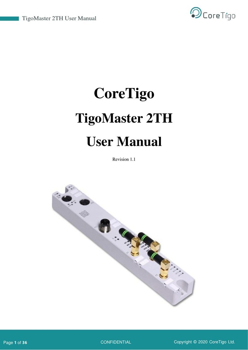
CoreTigo TigoMaster 2TH-PROFINET User manual

Copyright © 2021 CoreTigo Ltd.
CoreTigo
TigoMaster 2TH –PROFINET
User Manual

Copyright © 2021 CoreTigo Ltd.
TigoMaster 2TH –PROFINET User Manual
Page 2of 69
Table of Contents
1. Introduction .........................................................................................................................................7
1.1. About.............................................................................................................................................7
1.2. Typographical Conventions...........................................................................................................7
1.3. Symbols.........................................................................................................................................7
1.4. Deviating Views.............................................................................................................................7
2. Safety and Requirements...................................................................................................................8
2.1. General Note.................................................................................................................................8
2.2. Intended Use.................................................................................................................................8
2.3. Personnel Qualification .................................................................................................................8
2.4. Power Drop for Write/Delete Access in File System.....................................................................8
2.5. Exceeding the Max. No. of Permitted Write/Delete Access..........................................................9
2.6. Information and Data Security.......................................................................................................9
2.7. Regulatory Notices........................................................................................................................9
2.7.1. Class A Warnings - Industrial use.........................................................................................9
2.7.2. FCC Warning.........................................................................................................................9
2.7.3. ISED Warning........................................................................................................................9
2.7.4. Interference Statement........................................................................................................10
2.7.5. Wireless Notice ...................................................................................................................10
2.8. Requirements..............................................................................................................................10
2.8.1. Hardware and System Requirements.................................................................................10
2.8.2. Software Requirements.......................................................................................................11
3. Getting Started ..................................................................................................................................12
3.1. Description ..................................................................................................................................12
3.2. Overview .....................................................................................................................................12
3.2.1. Functionality ........................................................................................................................12
3.2.2. Lasering...............................................................................................................................14
3.2.3. Revisions and Versions.......................................................................................................14
3.2.4. Identification ........................................................................................................................15
3.2.5. LED Indications...................................................................................................................15
3.2.6. Connectors and Interfaces..................................................................................................18
4. Installation .........................................................................................................................................20
4.1. The Mounting Process ................................................................................................................20
4.1.1. Mounting..............................................................................................................................20
4.1.2. Grounding (optional) ...........................................................................................................22
4.1.3. Demounting.........................................................................................................................22

Copyright © 2021 CoreTigo Ltd.
TigoMaster 2TH –PROFINET User Manual
Page 3of 69
4.2. Connections and Booting............................................................................................................23
5. Configuration and Commissioning.................................................................................................25
5.1. Setting IP with the PROFINET IO-Controller..............................................................................26
5.1.1. Prerequisites .......................................................................................................................26
5.1.2. Connecting to the PLC........................................................................................................26
5.1.3. Configuring Submodules.....................................................................................................31
5.1.4. Port Submodule Parameters...............................................................................................34
5.2. Configuring TigoMaster 2TH with TigoEngine............................................................................35
5.2.1. Masters View.......................................................................................................................35
5.2.2. Connecting a New TigoMaster 2TH....................................................................................35
5.2.3. TigoEngine Connection Types............................................................................................37
5.2.4. Configuring Parameters ......................................................................................................37
5.3. Configuring TigoMaster 2TH with the Integrated Web Server (netFIELD) .................................38
5.3.1. Opening the Integrated Web Server ...................................................................................38
5.3.2. Overview of Configuration Tab and Scan Settings Tab......................................................39
5.3.3. TigoMaster 2TH Advanced Configuration View..................................................................39
5.4. Setting the TigoMaster 2TH IP Address using a DHCP Server..................................................39
5.4.1. Installing and using Open DHCP Server.............................................................................40
5.5. Setting the IP Address with the Ethernet Device Configuration Software ..................................40
5.6. Parameters..................................................................................................................................42
5.6.1. Port Cycle Time...................................................................................................................42
5.6.2. I-Am-Alive Time...................................................................................................................42
5.6.3. Parameters to Be Set for Connection 1 ..............................................................................44
6. OPC UA Server Connection .............................................................................................................48
TigoMaster 2TH...............................................................................................................................48
6.1. Identification................................................................................................................................48
6.2. Sensor/Actuator Identification.....................................................................................................49
6.3. Wireless Connection ...................................................................................................................49
7. Status and Diagnosis........................................................................................................................51
7.1. TigoMaster 2TH...........................................................................................................................51
7.2. PROFINET..................................................................................................................................51
7.2.1. Instance 0 (Class Attributes)...............................................................................................51
7.2.2. Instances 100, 101, … (Instance Attributes).......................................................................51
7.2.3. Attribute 14: Structure of a Log Entry..................................................................................53
7.2.4. Services...............................................................................................................................53
7.3. IO-Link.........................................................................................................................................54
7.3.1. Event Qualifier.....................................................................................................................54

Copyright © 2021 CoreTigo Ltd.
TigoMaster 2TH –PROFINET User Manual
Page 4of 69
7.3.2. IO-Link Wireless Master Event Codes................................................................................54
7.3.3. IO-Link Device Event Codes (Common).............................................................................55
8. Technical Data...................................................................................................................................58
8.1. Product Specifications.................................................................................................................58
8.2. Protocol Specifications................................................................................................................61
8.3. Dimensions..................................................................................................................................63
Appendix A –Part Number.......................................................................................................................64
Appendix B –Evaluation Agreement......................................................................................................65
List of Figures
Figure 1: TigoMaster 2TH (PROFINET Version)........................................................................................12
Figure 2: TigoMaster 2TH Identification Code............................................................................................15
Figure 3: Connection...................................................................................................................................24
Figure 4: Manage GSD Files.......................................................................................................................26
Figure 5: Manage General Station Description Files - Installed GSDs Tab ...............................................27
Figure 6: List of Available GSD Files ..........................................................................................................27
Figure 7 –New Module Added to Hardware Catalog .................................................................................28
Figure 8: Network View...............................................................................................................................28
Figure 9: Device View.................................................................................................................................29
Figure 10: Ethernet Addresses ...................................................................................................................30
Figure 11: Device Overview........................................................................................................................31
Figure 12: Device Inspector Window ..........................................................................................................31
Figure 13: Module Parameters ...................................................................................................................32
Figure 14: Unique ID...................................................................................................................................32
Figure 15: Show All Tags............................................................................................................................33
Figure 16: Tags Tab....................................................................................................................................33
Figure 17: Watch Table...............................................................................................................................34
Figure 18: Connect New Master Button......................................................................................................36
Figure 19: Connect Button..........................................................................................................................36
Figure 20: Masters View –One TigoMaster 2TH Connected.....................................................................37
Figure 21: Integrated Web Server Dashboard............................................................................................38
Figure 22: List of Devices Found in Local Network ....................................................................................41
Figure 23: IP Configuration Dialog Box.......................................................................................................41
Figure 24: Path to TigoMaster 2TH Device Identification Nodes................................................................48
Figure 25: Event Qualifier ...........................................................................................................................54
Figure 26: Dimensions................................................................................................................................63
List of Tables
Table 1: TigoMaster 2TH Functionality (PROFINET Version)....................................................................13
Table 2: TigoMaster 2TH Hardware............................................................................................................14
Table 3: TigoMaster 2TH Software.............................................................................................................14
Table 4: TigoMaster 2TH Firmware ............................................................................................................14
Table 5: System LEDs ................................................................................................................................15
Table 6: System LED States.......................................................................................................................15
Table 7: APL LEDs......................................................................................................................................16


Copyright © 2021 CoreTigo Ltd.
TigoMaster 2TH –PROFINET User Manual
Page 5of 69
Table 8: Supply Voltage LEDs....................................................................................................................16
Table 9: PROFINET IO-Device status ........................................................................................................16
Table 10: LED States PROFINET IO..........................................................................................................17
Table 11: Ethernet status............................................................................................................................17
Table 12: Ethernet LED States ...................................................................................................................17
Table 13: Wireless track status WT1 … WT3 .............................................................................................17
Table 14: Wireless track status WP01 … WP16.........................................................................................18
Table 15: Power Supply Connectors ..........................................................................................................18
Table 16: Ethernet Connectors...................................................................................................................19
Table 17: SMA Antenna..............................................................................................................................19
Table 18: Configuration Tools.....................................................................................................................25
Table 19: Port Submodule Parameters.......................................................................................................34
Table 20: Dashboard Information ...............................................................................................................38
Table 21: TigoMaster 2TH Advanced Configuration View..........................................................................39
Table 22: Port Cycle Time Calculation........................................................................................................42
Table 23: Time Base of I-Am-Alive Time ....................................................................................................43
Table 24: Calculation of I-Am-Alive Time....................................................................................................43
Table 25: Parameters 10 to 85 ...................................................................................................................44
Table 26: Parameter 90 ..............................................................................................................................45
Table 27: Parameters 410 to 456 ...............................................................................................................46
Table 28: Device Identification Nodes ........................................................................................................49
Table 29: Sensor/Actuator Identification Nodes .........................................................................................49
Table 30: Track and Slot (Double-Slot).......................................................................................................50
Table 31: Track and Slot (Single-Slot)........................................................................................................50
Table 32: Class Attributes Event Log Object 65 (0x41)..............................................................................51
Table 33: Mapping CIP Instances to IO-Link Ports.....................................................................................51
Table 34: Instance Attributes Event Log Object 65 (0x41) .........................................................................52
Table 35: Log Entry Structure.....................................................................................................................53
Table 36: Services Event Log Object 65 (0x41) .........................................................................................53
Table 37: Event Qualifier.............................................................................................................................54
Table 38: Master Event Codes....................................................................................................................54
Table 39: Device Event Codes....................................................................................................................55
Table 40: Product Specifications ................................................................................................................58
Table 41: Protocol Specifications................................................................................................................61
Version Control
Author Name
Description
Revision
Date

Copyright © 2021 CoreTigo Ltd.
TigoMaster 2TH –PROFINET User Manual
Page 6of 69
Acronyms and Abbreviations
Acronyms and abbreviations used in this document are listed in this table:
Term
Meaning
DSlot
Double Slot
FAT
File Allocation Table
FOTA
Firmware Upgrade Over the Air
FW
Firmware
HW
Hardware
IF
Interface
IOLW
IO-Link Wireless
ISDU
Indexed Service Data Unit
LQI
Link Quality Indicators
PDin
Process Data Input
PDout
Process Data Output
PER
Packet Error Rate
RSSI
Received Signal Strength Indication
SSlot
Single Slot
SW
Software
W-Device
Wireless Device
W-Master
Wireless Master

Copyright © 2021 CoreTigo Ltd.
TigoMaster 2TH –PROFINET User Manual
Page 7of 69
1. Introduction
1.1. About
This user manual describes the TigoMaster 2TH IO-Link Wireless Master. TigoMaster 2TH serves as a
wireless decentralized input/output device within an Ethernet Device Configuration Network.
The product and its firmware are under development so that functionality changes may occur. As such,
information provided in this user manual is preliminary and may not be complete or error free.
Note:
The TigoMaster 2TH IO-Link Wireless Master can be used with either the PROFINET
(Part Number: CT241-0003t2-02) or the EtherNet/IP (Part Number: CT241-0004t2-01)
protocol. This version of this user manual only focuses on the PROFINET protocol.
References:
•TigoEngine –User Manual
1.2. Typographical Conventions
•Enumerations are shown in a list form with bullet points.
•Instructional steps are shown in a numbered list form.
•Decimal numbers are shown without additional indicators and are not spelled out (e.g., 123).
1.3. Symbols
1.4. Deviating Views
The product views and illustrations in this user manual may deviate from the actual product. They are
intended only as illustrative material.
Symbol
Meaning
Note: This symbol indicates a general note.
Warning: This symbol indicates a security notice which must be observed.
Reference: This symbol indicates a cross-reference to other documentation ( available on
request).

Copyright © 2021 CoreTigo Ltd.
TigoMaster 2TH –PROFINET User Manual
Page 8of 69
2. Safety and Requirements
2.1. General Note
The users of this manual must be qualified for using such Device. All safety messages, integrated safety
messages, property damage messages, and valid legal regulations must be observed by users.
CoreTigo Ltd. assumes that users have the required Technical capabilities.
2.2. Intended Use
The TigoMaster 2TH IO-Link Wireless Master can be used to either acquire or output IO-Link field signals
to sensors, actuators, and hubs; with such signals being sent and received to a higher-level control
system.
The product is intended for indoor use only and in operating temperatures of -25°C to 55°C. It is protected
from damage caused by the accumulation of moisture on surfaces which are in contact with the air.
It is suitable for work environments requiring protection class IP67.
Warning:
Product applications other than those described in this user manual are not permitted.
2.3. Personnel Qualification
The product may only be mounted, configured, operated, or demounted by qualified personnel. Safety and
health at work regulations must be observed. When working with electricity, technical skills must be
demonstrated for all the following activities:
•Mounting and connecting of electrical equipment
•Measurement and analysis of electrical functions and systems
•Evaluation of the safety of electrical systems and equipment
Warning:
CoreTigo Ltd. does not assume any warranty or liability for damage caused to the product
due to non-compliance with safety measures or incorrect installation of the product.
2.4. Power Drop for Write/Delete Access in File System
The File Allocation Table (FAT) file system in the netX firmware is subject to certain operational
limitations. Specifically, write and delete access in the file system (for the purpose of firmware update,
configuration, download, and so forth) may destroy the FAT if access cannot be completed during power
drops.
Without such a proper FAT, firmware may not be found and can also not be started. Hence, it is important
to verify that the power supply of the device does not drop during write and delete access in the file
system.

Copyright © 2021 CoreTigo Ltd.
TigoMaster 2TH –PROFINET User Manual
Page 9of 69
2.5. Exceeding the Max. No. of Permitted Write/Delete Access
The device uses a serial flash chip to store remaining data, such as firmware and configuration storage. It
allows for a maximum of 100,000 write/delete accesses which suffice for standard operation of the
device.
However, writing/deleting the chip excessively (e.g., by modifying the configuration or station name) leads
to the maximum number of permitted write/delete accesses being exceeded, thereby causing damage to
the device. For example, if the configuration is changed once an hour, then the maximum number is
reached after 11,5 years. If changed more frequently, like once a minute, the number is reached after ~69
days.
As such, it is highly suggested to avoid exceeding the maximally permitted write/delete accesses.
2.6. Information and Data Security
Users are expected to follow all safety measures regarding information and data security which are
relevant for devices used with Ethernet technology.
Moreover, users are advised to install devices with access to a public network behind a firewall.
Otherwise, only make such devices accessible through a secure connection (e.g., an encrypted VPN
connection). If not, information and data integrity will not necessarily be safeguarded.
2.7. Regulatory Notices
2.7.1. Class A Warnings - Industrial use
This equipment has been tested and found to comply with the limits for a Class A digital device, pursuant
to Part 15 of the FCC rules. These limits are designed to provide reasonable protection against harmful
interference when the equipment is operated in a commercial environment.
This equipment generates, uses, and can radiate radio frequency energy and, if not installed and used in
accordance with the instructions, may cause harmful interference to radio communications.
Operation of this equipment in a residential area is likely to cause harmful interference, in which case the
user will be required to correct the interference at his own expense.
2.7.2. FCC Warning
Changes or modifications not expressly approved by the party responsible for compliance could void the
user's authority to operate the equipment.
FCC ID: 2ATSM-COR2TH
2.7.3. ISED Warning
CoreTigo Ltd. n’approuve aucune modification apportée à l’appareil par l’utilisateur, quelle qu’en soit la
nature. Tout changement ou modification peuvent annuler le droit d’utilisation de l’appareil par
l’utilisateur.

Copyright © 2021 CoreTigo Ltd.
TigoMaster 2TH –PROFINET User Manual
Page 10 of 69
2.7.4. Interference Statement
This device complies with Part 15 of the FCC Rules and Industry Canada licence-exempt RSS
standard(s). Operation is subject to the following two conditions:
1. this device may not cause interference, and,
2. this device must accept any interference, including interference that may cause undesired
operation of the device.
Le présent appareil est conforme aux CNR d'Industrie Canada applicables aux appareils radio exempts
de licence. L'exploitation est autorisée aux deux conditions suivantes:
1. l'appareil ne doit pas produire de brouillage, et
2. l'utilisateur de l'appareil doit accepter tout brouillage radioélectrique subi, même si le brouillage est
susceptible d'en compromettre le fonctionnement.
2.7.5. Wireless Notice
This device complies with FCC/ISED radiation exposure limits set forth for an uncontrolled environment
and meets the FCC radio frequency (RF) Exposure Guidelines and RSS‐102 of the ISED radio frequency
(RF) Exposure rules. This transmitter must not be co-located or operating in conjunction with any other
antenna or transmitter.
Le présent appareil est conforme à l'exposition aux radiations FCC / ISED définies pour un
environnement non contrôlé et répond aux directives d'exposition de la fréquence de la FCC
radiofréquence (RF) et RSS‐102 de la fréquence radio (RF) ISED règles d'exposition. L'émetteur ne doit
pas être colocalisé ni fonctionner conjointement avec à autre antenne ou autre émetteur.
2.8. Requirements
2.8.1. Hardware and System Requirements
The following hardware and system requirements enable the product’s installation:
•TigoMaster 2TH IO-Link Wireless Master
•24 V DC SELV (Safety Extra Low Voltage) or PELV (Protective Extra Low Voltage) Power Supply
•Power Supply Cable With L-Coded M12 Connector
•Ethernet Cable With D-Coded M12 Connector
•PROFINET Supported PLC (not mandatory)
•IO-Link Wireless Device or IO-Link Wireless Bridge (at least one)
•Wired IO-Link Device
•Ethernet Network Switch
•PC or Notebook with Min. 1 additional Ethernet Port and Internet Access/PLC
All components listed above are supplied by CoreTigo Ltd. upon purchase.

Copyright © 2021 CoreTigo Ltd.
TigoMaster 2TH –PROFINET User Manual
Page 11 of 69
2.8.2. Software Requirements
The following software requirements enable the product’s commissioning and configuration:
•TigoEngine Software Tool
•Internet Browser]

Copyright © 2021 CoreTigo Ltd.
TigoMaster 2TH –PROFINET User Manual
Page 12 of 69
3. Getting Started
3.1. Description
The TigoMaster 2TH IO-Link Wireless Master can be used within PROFINET network. TigoMaster 2TH is
parameterized via PROFINET network, with the device storing its parameters.
It may operate up to 16 IO-Link sensors/actuators via wireless connectivity.
All IO-Link Wireless ports can be configured with the supplied TigoEngine software tool (hereafter
referred to as TigoEngine). This way, users can set the parameters of all IO-Link Wireless
sensors/actuators connected to the device. Alternatively, IO-Link Wireless sensors/actuators can be
parameterized with an integrated web server (supplied by Hilscher). An OPC UA server is also integrated,
providing identification, statuses, and configuration capabilities.
3.2. Overview
3.2.1. Functionality
Figure 1: TigoMaster 2TH (PROFINET Version)

Copyright © 2021 CoreTigo Ltd.
TigoMaster 2TH –PROFINET User Manual
Page 13 of 69
The functionality illustrated by Figure 1 above is described in Table 1.
Table 1: TigoMaster 2TH Functionality (PROFINET Version)
Function
Number
Name
Description
Ethernet
(32)
X31
Ethernet interface, M12, D-coded, PROFINET IO port 1
(CH0)
(10)
X32
Ethernet interface, M12, D-coded, PROFINET IO port 2
(CH1)
(30)
LINK (X31)
Link LED for connector X31
(31)
ACT (X31)
Activity LED for connector X31
(28)
ACT (X32)
Activity LED for connector X32
(29)
LINK (X32)
Link LED for connector X32
(9)
-
Labeling fields Ethernet interfaces X31 and X32
LEDs
(34)
SYS
System status LED
(33)
APL
Application status LED
(7)
SF
System Failure LED
(8)
BF
Bus Failure LED
Power supply
(25)
X21
Power supply input (Power In), M12, L-coded
(13)
X22
Power supply output (Power Out), M12, L-coded
(12)
1L (X21)
1L supply voltage status LED (DC 24 V)
(14)
2L (X21)
2L supply voltage status LED (DC 24 V)
(11)
-
Labeling fields power supply input X21 and output X22
Antenna
connectors and
LEDs for IO- Link
wireless radio
module
(23)
X1
Connector for SMA antenna for IO-Link wireless
connection to the devices 1 to 8
(16)
X2
Connector for SMA antenna for IO-Link wireless
connection to the devices 9 to 16
(21)
X3
Connector for SMA antenna
(22),
(20)
-
Labeling fields SMA antennas X1, X2 and X3
(24)
WT1 … WT3
IO-Link wireless track status LEDs
(15)
WP01 …
WP08
Port status LEDs for
wireless IO-Link ports P01 to P08
(17)
WP09 …
WP16
Port status LEDs for
wireless IO-Link ports P09 to P16

Copyright © 2021 CoreTigo Ltd.
TigoMaster 2TH –PROFINET User Manual
Page 14 of 69
Function
Number
Name
Description
Device
identification
(26)
-
QR code
(27)
-
Product group and model
(35)
-
Part number, model, MAC address
(36)
-
Serial number
(19)
-
Device labeling field
Manufacturer
(37)
Manufacturer address
Technical data
(3), (5)
-
Certification sings (CE) and IDs (placeholders)
(4)
-
Power supply (SELV / PELV), fuse protection, temperature
range, protection class
Safety and
disposal
(2), (1)
-
Signs on safety and environment (disposal)
Mounting
(1)
-
Mounting hole (up) and grounding
(13)
-
Mounting hole (down)
3.2.2. Lasering
All technical data, such as the manufacturer’s address, product name, part number, serial number, MAC
address, certification signs (i.e., CEL, UL, etc.), environmental signs (i.e., disposal, etc.), and other data
alike is provided in the form of lasering on the right- or left-hand side of the device’s housing.
See Section 8 Technical Data for further technical details.
3.2.3. Revisions and Versions
The device’s hardware revision listed in Table 2 functionally belongs with the software and firmware
versions listed in Table 3 and Table 4 below. With any hardware installation, firmware must be updated.
Table 2: TigoMaster 2TH Hardware
Product Name
Description
Part Number
Hardware
Revision
TigoMaster 2TH-
PROFINET
IO-Link Wireless Master (PROFINET
Version)
CT241-0003t2-
01
Rev03
Table 3: TigoMaster 2TH Software
Software
Name
Version
Engineering Tool
TigoEngine
1.5
Integrated Web Server
netFIELD
1.2
PLC IDE
TIA Portal
V16
Table 4: TigoMaster 2TH Firmware

Copyright © 2021 CoreTigo Ltd.
TigoMaster 2TH –PROFINET User Manual
Page 15 of 69
Protocol
File Name
Version
PROFINET Adapter
UI197H001.nxi
2.0
3.2.4. Identification
A 2D data matrix code (DM code, 10x10mm) is provided on the front side of the TigoMaster 2TH device’s
housing. This code includes a part number, hardware revision, and serial number for device identification.
Figure 2: TigoMaster 2TH Identification Code
Additional identification data is provided in plain text on the right-hand side of the device’s housing.
Sample values:
•Product Name: 1234.567
•Part Number: 1912.122
•Serial Number: 2000
•MAC ID: 00-02-A2-2F-75-44
3.2.5. LED Indications
Table 5 through Table 14 specify the LED indications of the various LED types on the TigoMaster 2TH
device.
3.2.5.1. System LEDs
Table 5: System LEDs
LED
Color
State
Description
SYS
Green
On
The firmware is running
Green
Blinking
During the formatting of the file system
Yellow
On
A system error has occurred
Yellow/Green
Blinking (3x Yellow,
3x Green)
Firmware crash, unrecoverable (an internal exception
occurred that cannot be handled)
Yellow/Green
Blinking (1 Hz, 4 Hz)
•1 Hz: The maintenance firmware is idle (waiting for
update)
•4 Hz: The maintenance firmware is in operation:
Firmware update will be installed
Grey
Off
•No supply voltage: No supply voltage for the
device or hardware defect
•During a firmware reset
Table 6: System LED States
LED State
Description
Blinking
The display turns on and off in phases

Copyright © 2021 CoreTigo Ltd.
TigoMaster 2TH –PROFINET User Manual
Page 16 of 69
Blinking (3x Yellow,
3x Green)
The indicator turns on and off with a frequency of approx. 1 Hz:
•3x yellow "On" for 500 ms and "Off" for 500 ms
•3x green "On" for 500 ms and "Off" for 500 ms
Blinking (1 Hz, 4 Hz)
The indicator turns on in phases yellow or green with a frequency of
approximately:
•1 Hz: 1 x yellow "On" for 500 ms and 1 x green "On" for 500 ms
•4 Hz: 1 x yellow "On" for 125 ms and 1 x green "On" for 125 ms
3.2.5.2. APL LEDs
Table 7: APL LEDs
LED
Color
State
Description
APL
Green
On
IO-Link Wireless Master configured
Green
Blinking
Communication established
Yellow
On
Initialization of components done
Red
Blinking
Communication error
Grey
Off
Components not initialized
3.2.5.3. Supply Voltage LEDs
Table 8: Supply Voltage LEDs
LED Type
Color
State
Description
1L
Green
On
1L supply voltage OK
Grey
Off
No 1L supply voltage
2L
Green
On
2L supply voltage OK
Grey
Off
No 2L supply voltage
3.2.5.4. PROFINET IO-Device status
The SF (system failure) and BF (bus failure) LEDs indicate the status of the PROFINET IO-Device. The
LNK and ACT LEDs indicate the status of the Ethernet.
The following table describes the LED states of the PROFINET IO-Device.
Table 9: PROFINET IO-Device status
LED
Color
State
Description
SF
(System Failure)
(off)
Off
No error
(red)
Flashing
(1 Hz, 3 s)
DCP signal service is initiated via the bus.
(red)
On
Watchdog timeout; channel, generic or extended
diagnosis present; system error

Copyright © 2021 CoreTigo Ltd.
TigoMaster 2TH –PROFINET User Manual
Page 17 of 69
LED
Color
State
Description
BF
(Bus Failure)
(off)
Off
No error
(red)
Flashing
(2 Hz)
No data exchange
(red)
On
No configuration;
or low speed physical link; or no physical link
Table 10: LED States PROFINET IO
LED Status
Definition
Flashing (1 Hz, 3 s)
The indicator turns on and off for 3 seconds with a frequency of 1 Hz: “on” for 500
ms, followed by “off” for 500 ms.
Flashing (2 Hz)
The indicator turns on and off with a frequency of 2 Hz: “on” for 250 ms, followed
by “off” for 250 ms.
3.2.5.5. Ethernet Status LEDs
The following table describes the LED states of the link and activity LED.
Table 11: Ethernet status
LED
Color
State
Description
LILINK
(green)
On
The device is linked to the Ethernet.
(off)
Off
The device has no link to the Ethernet.
ACT
(yellow)
Flickering (load
dependent)
The device sends/receives Ethernet frames.
(off)
Off
The device does not send/receive Ethernet frames.
Table 12: Ethernet LED States
LED Status
Definition
Flickering (Load
Dependent)
The indicator turns on and off with a frequency of approximately 10 Hz to
indicate high Ethernet activity –On for approximately 50 ms, followed by
off for approximately 50 ms. The indicator turns on and off in irregular
intervals to indicate low Ethernet activity.
3.2.5.6. Wireless Track Status LEDs
The wireless track status LEDs WT1 … WT3 indicate the states for the wireless tracks 1, 2 and 3 as
described in the table below.
Table 13: Wireless track status WT1 … WT3
LED
Color
State
Description
WT1 … WT3
Duo LED red/green/yellow (yellow = red and green simultaneously)
(green)
On
Track operational mode and track service mode

Copyright © 2021 CoreTigo Ltd.
TigoMaster 2TH –PROFINET User Manual
Page 18 of 69
LED
Color
State
Description
(yellow)
On
Track inactive
(red)
Blinking
Track error
(gray)
Off
Track off
3.2.5.7. Wireless Port Status LEDs
The wireless port status LEDs WP01 … WP16 indicate the states for the wireless ports 1 … 16 as
described in the table below.
Table 14: Wireless track status WP01 … WP16
LED
Color
State
Description
WP01 … WP16
Duo LED red/green/yellow (yellow = red and green simultaneously)
(green)
On
Port operational
(green)
Blinking
Pairing success, communication ready
(yellow)
Blinking
Port ready
(red)
Blinking
Port communication lost
(red)
On
Port errors: Pairing timeout, pairing wrong slot-
type, revision fault, compatibility fault, serial
number fault, process data fault, or cycle time
fault.
(gray)
Off
Port inactive
3.2.6. Connectors and Interfaces
3.2.6.1. Power Supply
The device’s power is supplied via a connector named X21 (PWR IN). Once connected, users can
connect two supply lines to the connector which are both electrically isolated:
•Supply Line 1: 1L (U1L) and the reference potential 1M
•Supply Line 2: 2L (U2L) and the reference potential 2M
Each pin of connector X21 (PWR IN) is connected to the same pin of socket X22 (PWR OUT) and is used
to forward the power supply to the next device.
Table 15: Power Supply Connectors
PWR IN
PWR OUT
Pin
Signal
Description
1
1L+
+24 V DC power supply for system
and sensor, U1L
2
2L-
Reference potential for 2L.
3
1L-
Reference potential for 1L.

Copyright © 2021 CoreTigo Ltd.
TigoMaster 2TH –PROFINET User Manual
Page 19 of 69
M12, L-coded, male
5-pin (4 + FE) (X21)
M12, L-coded, female
5-pin (4 + FE) (X22)
4
2L+
+24 V DC power supply for
auxiliary/switched power supply, U2L
FE
FE
Functional earth
3.2.6.2. Ethernet
Users must use the following connectors to establish a connection with Ethernet interface ports of the
TigoMaster 2TH (PROFINET) device:
•Connector X31 for Ethernet interface port 1 (CH0)
•Connector X32 for Ethernet interface port 2 (CH1)
For identifying the connectors see Figure 1. Connector X31 is item (32), and connector X32 is item (10).
Table 16: Ethernet Connectors
Ethernet
Pin
Signal
Description
1
TX+
Transmit data, positive
2
RX+
Receive data, positive
3
TX–
Transmit data, negative
4
RX–
Receive data, negative
3.2.6.3. SMA Antenna
The TigoMaster 2TH device is equipped with two SMA antenna tracks. Each track supports up to 8, and
both tracks together support up to 16, IO-Link Wireless devices. The types of data transferred (e.g.,
length and data type) may vary depending on the connected IO-Link devices.
Table 17: SMA Antenna
SMA Antenna
Type
Manufacturer
2.4GHz Antenna - 2.4GHz,
5GHz
•Bandwidth: 1000 MHz
•Impedance: 50 Ohms
•Power Rating: 1 W
Tianlu Communication
TLW2.5A-SMA-Male
It is not permitted to use an alternative SMA antenna from the one supplied by CoreTigo
Ltd. Using an alternative SMA antenna may result in a loss of device approval.
Additionally, all three SMA antennas (X1, X2, and X3) must be mounted for proper device
functioning

Copyright © 2021 CoreTigo Ltd.
TigoMaster 2TH –PROFINET User Manual
Page 20 of 69
4. Installation
Install the hardware, driver, and firmware for the TigoMaster 2TH IO-Link Wireless Master according to
the installation guidelines described below.
General Preparation and Safety Guidelines:
•Get the device and mounting tools ready for installation
•Comply with all safety instructions relevant to the device and mounting tools
•Before mounting, disconnect the system to which the device will be mounted from the power
supply
The Mounting Process:
•Mark the positions to fasten the device with screws
•Cut the M4 holes
•Fasten the device with screws, ground it, and mount the SMA antennas
Connection and Booting:
•Connect the Ethernet M12 cable to TigoMaster 2TH device and to the TigoEngine software
and/or to PLC
•Connect the +24 V DC SELV or PELV power supply to the TigoMaster 2TH device (PROFINET)
•Connect the +24 V DC SELV or PELV power supply to the TigoBridge which is connected to a
sensor/actuator
•Switch on the power supply units of the TigoMaster device and of the TigoBridge
Commissioning and Configuration:
•The TigoMaster 2TH IO-Link Wireless Master is provided with a default IP address, i.e.,
192.168.1.1
•Configuration is done via TigoEngine, Integrated Web Server, and PLC configuration tool.
Continue reading the remainder of this Section for further details.
4.1. The Mounting Process
4.1.1. Mounting
Follow the instruction below to mount the device onto the chosen location.
General Requirements:
•Allen key for the M4 fixing screws with a hexagon socket
Other Requirements (If without an Existing Threaded Hole):
•M4 thread tap (ready-made or a set of taps)
•Drilling machine (to pre-drill the mounting holes for the device for mounting on the system)
•Two M4 hexagon socket head screws, according to DIN 912 / ISO 4762, of suitable length
Prerequisites:
This manual suits for next models
2
Table of contents
Other CoreTigo Network Hardware manuals

CoreTigo
CoreTigo TigoMaster 2TH User manual

CoreTigo
CoreTigo TigoBridge SOM User manual

CoreTigo
CoreTigo TigoBridge A1 User manual

CoreTigo
CoreTigo TigoMaster 2TH User manual

CoreTigo
CoreTigo TigoBridge A1 User manual

CoreTigo
CoreTigo TigoStarter K22 User manual

CoreTigo
CoreTigo TigoStarter K7 User manual

CoreTigo
CoreTigo TigoBridge B1 User manual

CoreTigo
CoreTigo TigoMaster 2TH User manual