AD Boivin 2002-03 Snowhawk User manual

2002-03
Set-up, service and repair
Manual
Snow Hawk™

FOREWORD
Congratulations, and thank you for buying an A.D.
Boivin design inc. Snow Hawk™ vehicle. We
appreciate the confidence in our product that you
have demonstrated by making this purchase.
Several years of design, tests and improvements
were necessary to produce this vehicle which
combines performance, driving pleasure and safety.
Proper maintenance on a regularly-scheduled basis is
essential in order to obtain the performance you have
the right to expect from your machine. In this manual,
you will find all the information needed for adjustments
to and the maintenance of this vehicle.
We sincerely hope that you will have many years of
enjoyment with your Snow Hawk™.
A D Boivin design inc.
All the information, illustrations, photographs and
specifications found in this manual are based on the
latest available data at the time of publication. Due to
improvements or other changes, it is possible that
you will note a few differences. A D Boivin design
reserves the right to make changes at any time.
WARNING /CAUTION / NOTICE
Please read this manual and follow the instructions
carefully. Pay particular attention to the boxes
entitled WARNING and CAUTION as well as to the
paragraphs preceded by the word NOTICE.
WARNING
This symbol is designed to call attention to
particular instructions and procedures, which,
if not followed to the letter, could cause injury
and even fatal accidents.
tt CAUTION
This symbol is designed to call attention to
particular instructions and procedures, which,
if not followed to the letter, could cause
damage to or even destruction of the vehicle.
lNOTICE:
The information in the NOTICES is designed to
explain maintenance procedures and to ensure the
best possible use of the vehicle.
IMPORTANT REMARKS
Using this vehicle can be a very pleasurable
experience and we wish you all the enjoyment that it
can bring you. However, if certain rules are not
respected, this sport can become a source of
environmental problems and of interpersonal
conflicts.
Adopting a responsible attitude and behaving in a
responsible manner at all times will help avoid such
problems and conflicts.
PROTECT THE FUTURE OF YOUR SPORT. BE
SURE TO RESPECT THE RULES AT ALL TIMES.
DEMONSTRATE AN AWARENESS OF THE
IMPORTANCE OF THE ENVIRONMENT AND
RESPECT THE RIGHTS OF OTHERS.
WARRANTY
1. All the parts of this vehicle are covered by the
warranty for a period of one winter season
against any problem related to its assembly
or construction.
2. The labour costs of repairs covered by the
warranty are the responsibility of the vehicle
owner.
3. The company reserves the right to require
that the dealer carrying out the repairs send
back any parts declared defective.
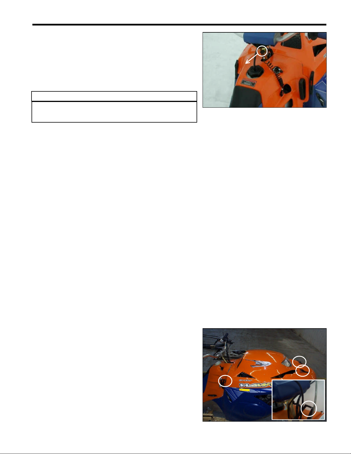
LOCATION OF THE V.I.N.

Warnings concerning maintenance
uu WARNING
Never have the motor running inside a building.
The exhaust fumes contain carbon monoxide, a
colourless, odourless gas which can cause
death or severe injuries.
Allow the motor to run only in a well-ventilated
area.
uu WARNING
When hot, a motor, an exhaust system or a
drive system can cause burns.
Wait until they have cooled before carrying out
maintenance.
uu WARNING
The gas tank can catch fire if it is not handled
correctly. Gas vapours can burst into flames
easily.
Do not smoke while carrying out vehicle
maintenance.
Do not carry out maintenance anywhere near
exposed flames or sparks.
uu WARNING
Brake fluid can be dangerous for people and
animals. These fluids are harmful or fatal if
swallowed and must not come into contact with
the skin or eyes.
uu WARNING
Carrying out maintenance of this vehicle while
the motor is running can be dangerous.
Injuries could result from contact with moving
parts.
Make sure you turn off the motor before
working on the vehicle.
uu WARNING
Working on this vehicle without wearing the
appropriate clothing can be dangerous.
Injuries could result if you are not adequately
protected.
Always wear the necessary equipment when
working on the vehicle: shoes, goggles, gloves
and/or mask if necessary.
Important information concerning maintenance
oReplace the joints, brake shoes and pins by new
ones.
oUse special tools when so indicated.
oUse original parts as well as recommended
products.
oAfter reassembling the vehicle, inspect the parts
and verify the torque on the nuts and bolts.
Replacement parts
Use only A D Boivin parts or their equivalent. A D
Boivin’s original high-quality parts are designed and
manufactured especially for your vehicle.
lNOTICE:
Using replacement parts that are not equivalent or
are of inferior quality could mean your vehicle will not
be able to perform as it should and could damage
your machine.

PICTOGRAMS AND THEIR MEANINGS
515 LocTite #515, Flange Sealant
Ultra LocTite Ultra Copper, High
Temperature Sealant
243
Non-permanent threadlocker
(blue)
262
Permanent threadlocker (red)
Brake fluid, DOT 4
Fork oil, S.A.E. 10W
Rear suspension shock oil,
Kayaba
Silicone grease
(P/N 420 8970 61)
Molybdenum Grease
(88162-74 / Dow corning)
Tighten a bolt or nut to a specified
torque
Replace a part by a new one when re-
assembling

TABLE OF CONTENTS
GENERAL INSTRUCTIONS
PERIODIC MAINTENANCE
FUEL SYSTEM
ENGINE REMOVAL
RECOIL STARTER
COOLING SYSTEM
ENGINE / CYLINDER AND CYLINDER HEADS
PRIMARY TRANSMISSION SYSTEM
SECONDARY TRANSMISSION SYSTEM
BRAKE SYSTEM
FRONT FORK AND SKI
REAR SUSPENSION, SHOCKS AND TRACK
CHASSIS AND STEERING
ELECTRICAL SYSTEM
DIMENSIONS AND TOLERANCES
SPECIAL TOOLS
WIRE, CABLE AND HOSE ROUTING
SPECIFICATIONS
1
2
3
4
5
6
7
8
9
10
12
13
14
15
16
17
18
11

GENERAL INSTRUCTIONS 1 -1
FIRST CONTACT
The SNOW HAWK™ is a brand new type of vehicle. Technically
speaking, it is a cross between a snowmobile and a motorcycle.
However, its behaviour depends on the conditions in which it is
used. Sometimes, it will react more like a bike while at other
times, it will react more like a snowmobile or a jetski.
Describing exactly how the SNOW HAWK™ behaves is difficult.
This is why we recommend that you take the time to become
acquainted with your machine in an area free of any obstacle.
This first contact should take place at low speed, with a series of
basic manoeuvres that will allow you to learn about the reactions
of the vehicle.
A good exercise is to follow a "figure 8" trajectory because this
will allow you to experiment with right-and left-hand turns
followed by accelerating and braking.
Turning can be done by steering right or left, keeping in mind the
speed of the vehicle, the snow conditions and how quickly you
want to change direction.
uuWARNING
Some people enter a turn by stretching out a leg on the
inside of the turn and letting the foot slide over the
ground (a technique used in motocross). We advise
against this practice which could cause severe injuries if
your foot should sink into the snow. We rather suggest
keeping both feet on the footpegs as much as possible.
An upright position, with the knees clutching the gas tank and
the elbows pointing away from the vehicle, will give a sense of
security and provide greater freedom of movement while
accelerating or slowing down.
uu WARNING
The greatest danger in using this vehicle is the perception
you may have of how competent you are. Overestimating
how competent you are can result in hazardous situations
both for yourself and for other trail users.
Do not forget to take all the time that is necessary for you to
practice and feel comfortable at low speeds before attempting
high-speed manoeuvres. You will then be able to fully
appreciate the joy of driving.
1

GENERAL INSTRUCTIONS 1 -2
LOCATION OF MECHANISMS AND CONTROLS
1. Throttle control
2. Brake lever
3. Parking brake lever
4. Engine-cutoff (tether)
5. Gas tank cap
6. Dimmer switch
7. Choke control
8. Emergency-stop button
9. Hood latches (4)
10. Rear module latches (4)
11. Bellypan latches (6)
12. Kick stand
13. Headlight
14. Stop and tail light
15. Recoil starter handle
16. Hood latches (4)
17. Rear module latches (4)
18. Bellypan latches (6)
9
10
11
12
13
14
15
16
17
18
6
2
3
1
4
5
7
8

GENERAL INSTRUCTIONS 1 -3
FUEL
This vehicle is powered by a two-stroke engine that uses a pre-
mixed gasoline and oil mixture.
Gasoline: Regular unleaded gas with a minimum octane
rating of 87 (R+M)/2
Motor oil: Bombardier / ROTAX Pre-mixture oil
Mixture ratio: 40 :1
Gas tank capacity: 17.5 litres
tt CAUTION
A mixture in which the proportion of oil is too low will
cause piston failure. On the other hand, a mixture in
which the proportion of oil is too high will cause
excessive carbon deposits that will result in fouled spark
plugs and will affect performance.
Always mix in a proportion of 40 parts of gasoline for
each part of oil.
lNOTICE:
oThe use of gas-line antifreeze is recommended in a ratio
of 150 mL per fuel tank in very cold temperatures.
oAvoid mixing oils of different brands.
Gasoline
( L )
Oil
( ml )
5125
10 250
15 375
20 500
25 625

GENERAL INSTRUCTIONS 1 -4
OPERATING INSTRUCTIONS
Pre-driving inspection
uu WARNING
A pre-driving inspection is of the utmost importance
before using the vehicle. Do not start the machine until
you are sure all mechanisms and controls are functioning
properly. Failing to proceed in the prescribed manner may
result in severe injuries or even death.
oMake sure the track and the idler wheels are not frozen and
that they move freely.
oDepress the brake lever and make sure the brake is fully
engaged before the end of the lever touches the handlebar.
The lever must return to its original position as soon as it is
released.
oTurn the twist throttle control a few times to make sure it
functions properly. The control must return automatically to
the idle position as soon as it is released.
oMake sure the engine cutoff switch, the stop light, the
headlight (high and low beams) and the tail light are in good
working order.
Starting the engine
oPut the cap of the engine cutoff (tether) in place. The other
end of the cord must be attached to the driver.
oIf the engine is cold, use the choke control.
0. Normal position (not activated)
1. Intermediate choke position
2. Full choke position
oStart the engine by firmly pulling the handle of the rewind
starter.
uu WARNING
Do not touch the throttle control while starting the engine.

GENERAL INSTRUCTIONS 1 -5
Stopping the engine
oWhile the engine is idling, remove the engine cutoff cap
(tether) or press the emergency-stop button.
BREAK-IN PERIOD
Engine
tt CAUTION
A break-in period of 10 to 15 hours is essential before
using the vehicle at full power.
During the break-in period, the throttle control should not be
turned more than ¾ of its range. However, occasional periods
of brief, brisk acceleration and frequent speed variations
contribute to a good break-in. On the other hand, periods of
long, high acceleration, sustained high speed and engine
overheating are harmful during the break-in period.
Belt
A new drive belt must be submitted to a 5-hour break-in period.
Avoid high-speed driving and brisk accelerations during this
period.
Inspection –10 hours
A general inspection is recommended after the first 10 hours of
use. This inspection must be carried out by an authorized
SNOW HAWK ™ dealer.
lNOTICE:
oMost of the wear in this product occurs during the break-in
period.
oBolts and nuts can easily become loose in a new machine.
Make sure you check them regularly during this period.
REMOVAL OF THE SHELL (HOOD, REAR
MODULE AND BELLY PAN)
In order to work on the vehicle more easily and to access the
anchor ties, we suggest that you remove the rear module from
the vehicle. To do so, you must first remove the hood. Proceed
as follows:
oDisconnect the front headlight.
oUnhook the 4 rubber latches (2 / side).
oRemove the hood.

GENERAL INSTRUCTIONS 1 -6
oTake off the fuel tank cap.
oSet the choke to the full position.
oUnplug the tail light connector located under the light
itself, underneath the rear fender.
oRelease the rear module from its four rubber latches,
slip the rewind starter handle through the space
provided and remove the rear module.
oRoll the two O-rings down and pull the two white plastic
collars down over the fork legs. To ensure that they will
not interfere, let them hang loose at the base of the fork
leg.
oRemove the circular fork disc
oDe-latch the two rubber latches on the sides of the belly
pan (towards the rear of the vehicle)
oDe-latch the four rubber latches on the bottom of the
belly pan.
oDescend the belly pan to floor level; most maintenance
can be performed with the belly pan in this position.
However, if it is required to completely remove the belly
pan, remove the single bolt attaching the ski to the fork.
At this point, a second person can lift the front of the
vehicle slightly and the belly pan can be slid out from
underneath.

PERIODIC MAINTENANCE 2 -1
lNOTICE:
Regular inspection and maintenance of the machine is of prime importance. Follow the guidelines in the following
table. Suggested times must be reduced if the vehicle is subjected to severe usage conditions.
Interval (Hrs)
Item
Fuel lines and connections
V
-
-
V
Carburetor adjustment
V
-
-
V
Throttle cable
V - A
-
-
V - A
Air Filters
V
-
-
V - C
Starter cord
V
-
-
V
Cylinder head bolts
V
-
-
V
Engine support bolts
V
-
-
V
Exhaust system
V
-
V
V
Cooling System
V
-
-
V
Primary drive belt
V
V
-
V - R
Primary and secondary clutch
V
-
V
V - C
Primary clutch bolt
V
-
-
V
Secondary clutch pre-tension
V - A
-
-
V - A
Secondary drive belt (cog belt)
V
-
-
V
Cog sprockets
V
-
-
V
Taper Locks
V
V
Brake fluid
V
-
-
F
Brake pads V-V - R V - R
Front Fork
F
-
F
F
Fork cushion
V
-
R
R
Ski and runners
V
V - R
Suspension
V
-
V
-
Shocks
V
-
V
F
Track
V & A
-
V - A
V - A
Handlebar bolts
V
-
-
V
Steering components
V
-
V
V
Assembly V- - V - C
Spark plugs
V - A - R
-
V - A - R
V - A - R
Spark plug gap
V & A
-
-
V & A
Headlight projection/aim
-
-
-
V & A
Lighting system, stop lamp and
emergency stop switch V V -V
65 Hrs
(yearlyl)
2.1 Carburetion
2.3 Primary transmission
system
2.2 Motor
Break-in
( ~ 10 Hrs. ) 5 Hrs
2.7 Rear suspension and
track
2.9 Electrical system
15 Hrs
2.5 Brake system
2.4 Secondary
transmission system
2.6 Front suspension and
ski
2.8 Chassis
V - R as needed
lNOTICE:
V = Verify, A = Adjust, C = Clean, R = Replace one or several part(s)
and F = Replace fluid
2

SCHEDULED MAINTENANCE 2 -2
2.1. CARBURETION
Fuel lines and connections
Check all hoses and connections in order to find and fix leaks or
to prevent them.
Carburetor adjustment
For carburetor adjustment, refer to the "Fuel system" section.
Throttle cable
The throttle cable can be adjusted by setting the adjustment
mechanism on the throttle control case.
For adjustment of the throttle cables at the carburetor end, refer
to the "Fuel system" section.
Air filters
Air filters must be cleaned at least once a year, or more often
under severe usage conditions. Clean the filters in a solution
containing a non-flammable cleaning solvant (such as hot soapy
water). Once they have dried, apply engine oil to the filters to
prevent the infiltration of water and dust.
2.2. ENGINE
Recoil starter cord
Pull gently on the handle to unwind the full length of the cable.
Inspect the cable visually to detect any wear or other damage
that could eventually cause the cord to break.
Cylinder head bolts
Refer to the appropriate procedure in the "Engine" section.
Engine support bolts
To carry out this operation, refer to the appropriate procedure in
the "Engine" section.

PERIODIC MAINTENANCE 2 -3
Exhaust system
Using a torque wrench, check the torque of the retaining bolts of
the exhaust manifold. Apply a torque of 22 N-m (2.2 kg-m, 16.2
lbf-ft).
Then, proceed to a visual inspection of the system to detect any
leak or abnormality.
Cooling system
Remove the fan cover and check the condition and tension of
the fan belt. Check the general condition of the belt, especially
the presence of cuts or tears. If in doubt as to the condition of
the belt, replace with a new one. The belt must show a
deflection of 9.5 mm (3/8 in) when a 5 Kg (11 lb) perpendicular
force is applied.
1. Deflection
2.3. PRIMARY TRANSMISSION
Primary and secondary clutches
Remove the belt and verify that the sliding half-pulleys of the two
pulleys are in good working condition.
To take the belt off, first use the special tool provided to open
the secondary clutch. Then, slip the belt over the pulley from
front to rear as illustrated. To reinstall the belt, proceed in the
reverse order.

SCHEDULED MAINTENANCE 2 -4
Primary clutch bolt
Check the torque on the primary clutch retaining bolt.
Recommended torque: 90 -100 N-m (9–10 kg-m, 66.4 lbf-ft).
For more information, refer to the "Primary transmission"
section.
Pre-tension of the secondary clutch spring
For more information, refer to the "Primary transmission"
section.
Primary transmission belt
Examine the belt. Make sure it is not cracked, frayed or worn in
an abnormal way (uneven wear, wear on one side only, missing
cogs, or cracked material). Abnormal wear of the belt is often
due to mis-alignment of the pulleys, excessive speed when the
track is frozen, quick acceleration without preliminary warming
up, a scratched or rusted pulley, oil on the belt, or a twisted
replacement belt. If need be, ask an authorized SNOW
HAWK™ dealer for advice.
Measure the width of the belt. Replace if it is less than 31.6 mm
(1.245 in) wide.
For more information, refer to the "Primary transmission"
section.
2.4. SECONDARY TRANSMISSION
Secondary transmission cog belt
Examine the belt. Make sure it is not cracked, frayed or worn in
an abnormal way. If in doubt as to the condition of the belt,
replace it with a new one.
Verify the tension of the secondary transmission belt according
to the instructions found in the "Secondary transmission"
section.

PERIODIC MAINTENANCE 2 -5
Cog Sprockets
Check the appearance of the cog sprockets. Make sure all the
sprockets are there and are free of any accumulated dirt. Clean
if necessary.
Taper-locks
Refer to the "Secondary transmission" section.
2.5. BRAKE SYSTEM
Brake fluid
Check to see if the brake fluid level is above the "mimimum"
mark (see illustration). If not, add fluid.
tt CAUTION
Use only DOT 4 brake fluid from a sealed container. Do
not use any other type of brake fluid.
Brake pads
Verify the thickness of the brake pad linings as illustrated. Brake
pads must both be replaced if either one of them shows a
clearance of less than 1 mm (1/32 in.).
lNOTICE:
For the replacement of brake fluid, refer to the "Brake system"
section.
MIN

SCHEDULED MAINTENANCE 2 -6
2.6. FRONT SUSPENSION AND SKI
Front fork
The air pressure inside the fork legs must be as close as
possible to atmospheric pressure. Therefore, it is advisable to
remove the bleeder screws from time to time to re-establish the
pressure. It should be done more frequently when temperature
variations are greater and more frequent.
A visual inspection of the fork legs can reveal oil leaks that might
indicate broken main seals.
It is recommended to replace the fork oil after the break-in
period and, from then on, after every 15 hours of use. For
details, refer to the "Front suspension and ski" section.
tt CAUTION
It is advisable to change the fork fluid when preparing the
vehicle for storage. The presence of condensation in the
suspension fluid could cause rusting to occur during the
storage period.
Ski and runners
Verify the torque of all the bolts holding the ski, as well as all the
steds and nuts retaining the runners. Also inspect the
appearance of the runners to detect any wear, distortion, or
broken studs.
2.7. REAR SUSPENSION AND TRACK
Suspension
Verify that all suspension bolts and nuts are well tightened.
Verify that none of the parts are damaged or missing.
Verify that the suspension wheel bearings are in good working
order.
Verify the condition of the suspension limiter straps.
Verify the condition of the slides.
For more information, refer to the "Rear suspension and track"
section.

PERIODIC MAINTENANCE 2 -7
Shock absorbers
Check around the shock guards for the presence of oil leaks.
Shock oil must be replaced once a year. Refer to the "Rear
suspension and track" section.
tt CAUTION
It is advisable to change the shock fluid when preparing
the vehicle for storage. The presence of condensation in
the suspension fluid could cause rusting to occur during
the storage period.
Track
Check the condition, alignment and tension of the track.
With the engine turned off and the rear end of the machine
raised from the ground, rotate the track manually and inspect it
to make sure it is in good working condition. It must not be
cracked and all the lugs must be intact.
lNOTICE:
For track alignment and tension, refer to the "Rear suspension
and track" section.
2.8. CHASSIS AND STEERING
Handlebar mounting bolts
Verify and adjust the torque to 36.5 N-m (3.7 kg-m, 27 lbf-ft),
following a criss-cross order.

SCHEDULED MAINTENANCE 2 -8
Steering mechanism
Verify the condition of the ball joints and check for excessive
play in the pivots of the steering system. For alignment, refer to
the "Chassis and steering" section.
Assembly
The chassis of the SNOW HAWK is different in that most of the
assembly is done by bolting components rather than welding
them. Therefore, bolts must be checked and tightened as need
be. When doing this, refer to the table entitled "TORQUES" at
the end of this section.
2.9. ELECTRICAL SYSTEM
Spark plug
Check the general condition of the plug, the colour of its
electrodes, carbon deposits, plug gap and possible damages to
the gasket
A NGK BR9ES spark plug is recommended.
Check the spark plug gap. The suggested gap is 0.45 mm
(0.018").
When tightening the spark plug, the torque must be between 25
and 30 N-m(18 and 21.5 lbf-ft; 2.5 and 3.0 kg-m).
Surchauffée
(gris clair) Normale
(brunâtre) Encrasée
(noirâtre)

PERIODIC MAINTENANCE 2 -9
Porcelain colour
Probable cause
-Plug temperature rating too high
(No. is too small)
-
Plug gap too wide
-
Air / fuel mixture too lean
-
Stale gasoline
-Plug temperature rating too low
(No. is too big)
-Plug gap too close
-
Air / fuel mixture too rich
-
Oil / fuel mixture too rich
Light Grey (Overheated)
Blackish (fouled)
tt CAUTION
The engine may be seriously damaged if the temperature
rating of the spark plug is inadequate.
Refer to the NGK codification on the next page.
This manual suits for next models
1
Table of contents
Other AD Boivin Offroad Vehicle manuals