ADADVANCED Motion Controls DigiFlex Performance Assembly instructions
Everything’s possible.
www.a-m-c.com
Hardware Installation Manual
DigiFlex® Performance™ DPP Drives
POWERLINK / Modbus TCP / Ethernet Communication
MNDGDPIN-06
ORIGINAL INSTRUCTIONS

MNDGDPIN-06 ii
Preface
ADVANCED Motion Controls constantly strives to improve all of its products. We review the information in
this document regularly and we welcome any suggestions for improvement. We reserve the right to modify
equipment and documentation without prior notice.
For the most recent software, the latest revisions of this manual, and copies of compliance and
declarations of conformity, visit the company’s website at www.a-m-c.com. Otherwise, contact the
company directly at:
ADVANCED Motion Controls •3805 Calle Tecate Camarillo, CA •93012-5068 USA
Agency Compliances
The company holds original documents for the following:
•UL 508c, file number E140173
•Electromagnetic Compatibility, EMC Directive - 2014/30/EU
EN61000-6-2:2005
EN61000-6-4:2007/A1:2011
•Electrical Safety, Low Voltage Directive - 2014/35/EU
EN 60204-1:2006/A1:2009
•Reduction of Hazardous Substances (RoHS II), 2011/65/EU
•Functional Safety Type Approved, TUV Rheinland
Trademarks
ADVANCED Motion Controls®, the combined isosceles trapezoid/right triangle logo, DIGIFLEX®,
DIGIFLEX® Performance™ and DriveWare® are either registered trademarks or trademarks of ADVANCED
Motion Controls in the United States and/or other countries. All other trademarks are the property of their
respective owners.
Related Documentation
•Product datasheet specific for your drive, available for download at www.a-m-c.com
•DriveWare Software Guide, available for download at www.a-m-c.com
•POWERLINK Communication Manual, available for download at www.a-m-c.com
•Modbus Communication Manual, available for download at www.a-m-c.com
•Ethernet Communication Manual, available for download at www.a-m-c.com
/
iii MNDGDPIN-06
Attention Symbols
The following symbols are used throughout this document to draw attention to important operating
information, special instructions, and cautionary warnings. The section below outlines the overall directive
of each symbol and what type of information the accompanying text is relaying.
Revision History
Document ID Revision # Date Changes
MNDGDPIN-01 13/2015 DPP Install Manual First Release
MNDGDPIN-02 210/2015 Added Ethernet POWERLINK as a supported network communication type
MNDGDPIN-03 33/2016 Added -040A400 power module information
MNDGDPIN-04 44/2017 Added -030A800 and -060A800 power module information
MNDGDPIN-05 511/2017 Added -100B080 power module information
MNDGDPIN-06 65/2018 - Added 2-Phase Stepper motor information
- Added PDO power-up delay information
© 2018 ADVANCED Motion Controls. All rights reserved.
Note - Pertinent information that clarifies a process, operation, or ease-
of-use preparations regarding the product.
Notice - Required instruction necessary to ensure successful completion
of a task or procedure.
Caution - Instructs and directs you to avoid damaging equipment.
Warning - Instructs and directs you to avoid harming yourself.
Danger - Presents information you must heed to avoid serious injury or
death.
Note

MNDGDPIN-06 iv
Contents
1 Safety 1
1.1 General Safety Overview . . . . . . . . . . . . . . . . . . . . . . . . . . . . . . . . 1
2 Products and System Requirements 4
2.1 DPP Drive Family Overview . . . . . . . . . . . . . . . . . . . . . . . . . . . . . . . 4
2.1.1 Drive Datasheet . . . . . . . . . . . . . . . . . . . . . . . . . . . . . . . . . . . 4
2.2 Products Covered . . . . . . . . . . . . . . . . . . . . . . . . . . . . . . . . . . . . . . 5
2.2.1 Control Module . . . . . . . . . . . . . . . . . . . . . . . . . . . . . . . . . . . 7
2.3 Communication Protocol . . . . . . . . . . . . . . . . . . . . . . . . . . . . . . . . 8
2.4 Control Modes . . . . . . . . . . . . . . . . . . . . . . . . . . . . . . . . . . . . . . . . . 9
2.4.1 Profile Modes . . . . . . . . . . . . . . . . . . . . . . . . . . . . . . . . . . . . . 9
Profile Current (Torque) . . . . . . . . . . . . . . . . . . . . . . . . . . . . . 9
Profile Velocity . . . . . . . . . . . . . . . . . . . . . . . . . . . . . . . . . . . . 9
Profile Position . . . . . . . . . . . . . . . . . . . . . . . . . . . . . . . . . . . . . 9
2.4.2 Cyclic Synchronous Modes . . . . . . . . . . . . . . . . . . . . . . . . . 9
Cyclic Synchronous Current . . . . . . . . . . . . . . . . . . . . . . . . 10
Cyclic Synchronous Velocity . . . . . . . . . . . . . . . . . . . . . . . . 10
Cyclic Synchronous Position . . . . . . . . . . . . . . . . . . . . . . . . 10
2.4.3 Current (Torque) . . . . . . . . . . . . . . . . . . . . . . . . . . . . . . . . . 10
2.4.4 Velocity . . . . . . . . . . . . . . . . . . . . . . . . . . . . . . . . . . . . . . . . . 10
2.4.5 Position . . . . . . . . . . . . . . . . . . . . . . . . . . . . . . . . . . . . . . . . . 10
2.5 Feedback Supported . . . . . . . . . . . . . . . . . . . . . . . . . . . . . . . . . . . 11
Feedback Polarity . . . . . . . . . . . . . . . . . . . . . . . . . . . . . . . . 11
2.5.1 Incremental Encoder . . . . . . . . . . . . . . . . . . . . . . . . . . . . . 11
2.5.2 Absolute Encoder . . . . . . . . . . . . . . . . . . . . . . . . . . . . . . . . 12
2.5.3 1Vp-p Sin/Cos Encoder . . . . . . . . . . . . . . . . . . . . . . . . . . . . 13

MNDGDPIN-06 v
/
2.5.4 Hall Sensors . . . . . . . . . . . . . . . . . . . . . . . . . . . . . . . . . . . . . . 13
2.5.5 Auxiliary Incremental Encoder . . . . . . . . . . . . . . . . . . . . . . 13
2.5.6 Tachometer (±10 VDC) . . . . . . . . . . . . . . . . . . . . . . . . . . . . 13
2.5.7 ±10 VDC Position . . . . . . . . . . . . . . . . . . . . . . . . . . . . . . . . . 13
2.6 Command Sources . . . . . . . . . . . . . . . . . . . . . . . . . . . . . . . . . . . . 14
2.6.1 ±10V Analog . . . . . . . . . . . . . . . . . . . . . . . . . . . . . . . . . . . . . 14
2.6.2 Encoder Following . . . . . . . . . . . . . . . . . . . . . . . . . . . . . . . . 14
2.6.3 Indexing and Sequencing . . . . . . . . . . . . . . . . . . . . . . . . . 14
2.6.4 Jogging . . . . . . . . . . . . . . . . . . . . . . . . . . . . . . . . . . . . . . . . . 14
2.6.5 Over the Network . . . . . . . . . . . . . . . . . . . . . . . . . . . . . . . . 14
2.7 System Requirements . . . . . . . . . . . . . . . . . . . . . . . . . . . . . . . . . . . 15
2.7.1 Specifications Check . . . . . . . . . . . . . . . . . . . . . . . . . . . . . 15
2.7.2 Motor Specifications . . . . . . . . . . . . . . . . . . . . . . . . . . . . . . 15
2.7.3 Power Supply Specifications . . . . . . . . . . . . . . . . . . . . . . . 16
2.7.4 Environment . . . . . . . . . . . . . . . . . . . . . . . . . . . . . . . . . . . . . 17
Shock/Vibrations . . . . . . . . . . . . . . . . . . . . . . . . . . . . . . . . . . 17
Ambient Temperature Range and Thermal Data . . . . . . 17
3 Integration in the Servo System 19
3.1 LVD Requirements . . . . . . . . . . . . . . . . . . . . . . . . . . . . . . . . . . . . . 19
3.2 CE-EMC Wiring Requirements . . . . . . . . . . . . . . . . . . . . . . . . . . . . 20
General . . . . . . . . . . . . . . . . . . . . . . . . . . . . . . . . . . . . . . . . . 20
Analog Input Drives . . . . . . . . . . . . . . . . . . . . . . . . . . . . . . . 20
PWM Input Drives . . . . . . . . . . . . . . . . . . . . . . . . . . . . . . . . . 20
MOSFET Switching Drives . . . . . . . . . . . . . . . . . . . . . . . . . . . 20
IGBT Switching Drives . . . . . . . . . . . . . . . . . . . . . . . . . . . . . . 20
Fitting of AC Power Filters . . . . . . . . . . . . . . . . . . . . . . . . . . 20
3.2.1 Ferrite Suppression Core Set-up . . . . . . . . . . . . . . . . . . . . . 21
3.2.2 Inductive Filter Cards . . . . . . . . . . . . . . . . . . . . . . . . . . . . . . 21
3.3 Grounding . . . . . . . . . . . . . . . . . . . . . . . . . . . . . . . . . . . . . . . . . . . . 22
3.4 Wiring . . . . . . . . . . . . . . . . . . . . . . . . . . . . . . . . . . . . . . . . . . . . . . . . 23
3.4.1 Wire Gauge . . . . . . . . . . . . . . . . . . . . . . . . . . . . . . . . . . . . . 23
3.4.2 Motor Wires . . . . . . . . . . . . . . . . . . . . . . . . . . . . . . . . . . . . . . 24
3.4.3 Power Supply Wires . . . . . . . . . . . . . . . . . . . . . . . . . . . . . . . 24
3.4.4 Feedback Wires . . . . . . . . . . . . . . . . . . . . . . . . . . . . . . . . . . 24
3.4.5 I/O and Signal Wires . . . . . . . . . . . . . . . . . . . . . . . . . . . . . . 25
3.5 Connector Types . . . . . . . . . . . . . . . . . . . . . . . . . . . . . . . . . . . . . . 26
3.5.1 Power Connectors . . . . . . . . . . . . . . . . . . . . . . . . . . . . . . . . 26

MNDGDPIN-06 vi
/
3.5.2 Feedback Connectors . . . . . . . . . . . . . . . . . . . . . . . . . . . . 28
3.5.3 I/O Connectors . . . . . . . . . . . . . . . . . . . . . . . . . . . . . . . . . . 29
3.5.4 Communication Connectors . . . . . . . . . . . . . . . . . . . . . . . 29
3.5.5 STO Connector . . . . . . . . . . . . . . . . . . . . . . . . . . . . . . . . . . 30
3.6 Mounting . . . . . . . . . . . . . . . . . . . . . . . . . . . . . . . . . . . . . . . . . . . . . 30
4 Operation and Features 31
4.1 Features and Getting Started . . . . . . . . . . . . . . . . . . . . . . . . . . . . 31
4.1.1 Initial Setup and Configuration . . . . . . . . . . . . . . . . . . . . . 31
4.1.2 Input/Output Pin Functions . . . . . . . . . . . . . . . . . . . . . . . . . 33
Programmable Digital I/O . . . . . . . . . . . . . . . . . . . . . . . . . . 33
Programmable Limit Switch (PLS) Outputs . . . . . . . . . . . . 35
Auxiliary Encoder Input . . . . . . . . . . . . . . . . . . . . . . . . . . . . 36
Programmable Analog I/O . . . . . . . . . . . . . . . . . . . . . . . . . 36
Motor Thermistor . . . . . . . . . . . . . . . . . . . . . . . . . . . . . . . . . . 36
4.1.3 Feedback Operation . . . . . . . . . . . . . . . . . . . . . . . . . . . . . 37
Absolute Encoder . . . . . . . . . . . . . . . . . . . . . . . . . . . . . . . . . 37
1 Vp-p Sin/Cos Encoder . . . . . . . . . . . . . . . . . . . . . . . . . . . 37
Incremental Encoder . . . . . . . . . . . . . . . . . . . . . . . . . . . . . . 38
Hall Sensors . . . . . . . . . . . . . . . . . . . . . . . . . . . . . . . . . . . . . . 38
Tachometer (±10 VDC) . . . . . . . . . . . . . . . . . . . . . . . . . . . . 38
4.1.4 Logic Power Supply . . . . . . . . . . . . . . . . . . . . . . . . . . . . . . . 39
4.1.5 Power Supply Connections . . . . . . . . . . . . . . . . . . . . . . . . 40
AC or DC Power Modules . . . . . . . . . . . . . . . . . . . . . . . . . . 40
DC Only Power Modules . . . . . . . . . . . . . . . . . . . . . . . . . . . 41
4.1.6 Power LEDs Functionality . . . . . . . . . . . . . . . . . . . . . . . . . . 41
Power LED . . . . . . . . . . . . . . . . . . . . . . . . . . . . . . . . . . . . . . . 41
Status LED . . . . . . . . . . . . . . . . . . . . . . . . . . . . . . . . . . . . . . . 41
4.1.7 Motor Connections . . . . . . . . . . . . . . . . . . . . . . . . . . . . . . . 42
4.1.8 External Shunt Resistor Connections . . . . . . . . . . . . . . . . . 43
4.1.9 STO (Safe Torque Off) . . . . . . . . . . . . . . . . . . . . . . . . . . . . . 44
STO Disable . . . . . . . . . . . . . . . . . . . . . . . . . . . . . . . . . . . . . . 45
STO Operation Test . . . . . . . . . . . . . . . . . . . . . . . . . . . . . . . . 45
4.1.10 Communication and Commissioning . . . . . . . . . . . . . . . 46
Ethernet Node ID/Address . . . . . . . . . . . . . . . . . . . . . . . . . . 46
Network Communication LEDs Functionality . . . . . . . . . . 46
4.1.11 Commutation . . . . . . . . . . . . . . . . . . . . . . . . . . . . . . . . . . . 48
Sinusoidal Commutation . . . . . . . . . . . . . . . . . . . . . . . . . . . 48

MNDGDPIN-06 vii
/
Trapezoidal Commutation . . . . . . . . . . . . . . . . . . . . . . . . . 48
4.1.12 Homing . . . . . . . . . . . . . . . . . . . . . . . . . . . . . . . . . . . . . . . . 49
4.1.13 Firmware . . . . . . . . . . . . . . . . . . . . . . . . . . . . . . . . . . . . . . . 49
A Specifications 50
A.1 Specifications Tables . . . . . . . . . . . . . . . . . . . . . . . . . . . . . . . . . . . 50
B Troubleshooting 52
B.1 Fault Conditions and Symptoms . . . . . . . . . . . . . . . . . . . . . . . . . . 52
Over-Temperature . . . . . . . . . . . . . . . . . . . . . . . . . . . . . . . . 52
Over-Voltage Shutdown . . . . . . . . . . . . . . . . . . . . . . . . . . . 52
Under-Voltage Shutdown . . . . . . . . . . . . . . . . . . . . . . . . . . 52
Short Circuit Fault . . . . . . . . . . . . . . . . . . . . . . . . . . . . . . . . . 53
Invalid Hall Sensor State . . . . . . . . . . . . . . . . . . . . . . . . . . . . 53
B.1.1 Software Limits . . . . . . . . . . . . . . . . . . . . . . . . . . . . . . . . . . . 53
B.1.2 Connection Problems . . . . . . . . . . . . . . . . . . . . . . . . . . . . . 53
B.1.3 Overload . . . . . . . . . . . . . . . . . . . . . . . . . . . . . . . . . . . . . . . 53
B.1.4 Current Limiting . . . . . . . . . . . . . . . . . . . . . . . . . . . . . . . . . . 54
B.1.5 Motor Problems . . . . . . . . . . . . . . . . . . . . . . . . . . . . . . . . . . 54
B.1.6 Causes of Erratic Operation . . . . . . . . . . . . . . . . . . . . . . . . 54
B.2 Technical Support . . . . . . . . . . . . . . . . . . . . . . . . . . . . . . . . . . . . . . 55
B.2.1 Drive Model Information . . . . . . . . . . . . . . . . . . . . . . . . . . . 55
B.2.2 Product Label Description . . . . . . . . . . . . . . . . . . . . . . . . . 55
B.2.3 Warranty Returns and Factory Help . . . . . . . . . . . . . . . . . 56
Index I
MNDGDPIN-06 1
1 Safety
This section discusses characteristics of your DPP digital drive to raise your awareness of potential risks and
hazards. The severity of consequences ranges from frustration of performance, through damage to equipment,
injury or death. These consequences, of course, can be avoided by good design and proper installation into your
mechanism.
1.1 General Safety Overview
In order to install a DPP drive into a servo system, you must have a thorough knowledge and
understanding of basic electronics, computers and mechanics as well as safety precautions
and practices required when dealing with the possibility of high voltages or heavy, strong
equipment.
You must install and operate motion control equipment so that you meet
all applicable safety requirements. Ensure that you identify the relevant
standards and comply with them. Failure to do so may result in damage
to equipment and personal injury.
Read this entire manual prior to attempting to install or operate the drive.
Become familiar with practices and procedures that allow you to
operate these drives safely and effectively. You are responsible for
determining the suitability of this product for the intended application.
The manufacturer is neither responsible nor liable for indirect or
consequential damages resulting from the inappropriate use of this
product.
Over current protective devices recognized by an international safety
agency must be installed in line before the servo drive. These devices
shall be installed and rated in accordance with the device installation
instructions and the specifications of the servo drive (taking into
consideration inrush currents, etc.). Servo drives that incorporate their
own primary fuses do not need to incorporate over current protection in
the end user’s equipment.
Observe your facility’s lock-out/tag-out procedures so that work can proceed without residual
power stored in the system or unexpected movements by the machine.
High-performance motion control equipment can move rapidly with
very high forces. Unexpected motion may occur especially during
product commissioning. Keep clear of any operational machinery and
never touch them while they are working.
Keep clear of all exposed power terminals (motor, DC Bus, shunt, DC
power, transformer) when power is applied to the equipment. Follow
these safety guidelines:
•When using a separate logic supply, turn on the logic power supply
first before turning on the main power supply.
•Always turn off the main power and allow sufficient time for
complete discharge before making any connections to the drive.
•Do not rotate the motor shaft without power. The motor acts as a
generator and will charge up the power supply capacitors through
the drive. Excessive speeds may cause over-voltage breakdown in
the power output stage. Note that a drive having an internal power
converter that operates from the high voltage supply will become
operative.
•Do not short the motor leads at high motor speeds. When the motor is
shorted, its own generated voltage may produce a current flow as
high as 10 times the drive current. The short itself may not damage
the drive but may damage the motor. If the connection arcs or
opens while the motor is spinning rapidly, this high voltage pulse flows
back into the drive (due to stored energy in the motor inductance)
and may damage the drive.
•Do not make any connections to any internal circuitry. Only
connections to designated connectors are allowed.
•Do not make any connections to the drive while power is applied.
•Do not reverse the power supply leads! Severe damage will result!
•If using relays or other means to disconnect the motor leads, be sure
the drive is disabled before reconnecting the motor leads to the
drive. Connecting the motor leads to the drive while it is enabled can
generate extremely high voltage spikes which will damage the drive.
Use sufficient capacitance!
Pulse Width Modulation (PWM) drives require a capacitor on the high
voltage supply to store energy during the PWM switching process.
Insufficient power supply capacitance causes problems particularly with
high inductance motors. During braking much of the stored mechanical
energy is fed back into the power supply and charges its output
capacitor to a higher voltage. If the charge reaches the drive’s over-
voltage shutdown point, output current and braking will cease. At that
time energy stored in the motor inductance continues to flow through
diodes in the drive to further charge the power supply capacitance. The
voltage rise depends upon the power supply capacitance, motor
speed, and inductance.
MNDGDPIN-06 2
Safety / General Safety Overview

MNDGDPIN-06 3
Safety / General Safety Overview
Make sure minimum inductance requirements are met!
Pulse Width Modulation (PWM) servo drives deliver a pulsed output that
requires a minimum amount of load inductance to ensure that the DC
motor current is properly filtered. The minimum inductance values for
different drive types are shown in the individual data sheet
specifications. If the drive is operated below its maximum rated voltage,
the minimum load inductance requirement may be reduced. Most
servo-motors have enough winding inductance. Some types of motors
(e.g. "basket-wound", "pancake", etc.) do not have a conventional iron
core rotor, so the winding inductance is usually less than 50 μH.
If the motor inductance value is less than the minimum required for the
selected drive, use an external filter card.

MNDGDPIN-06 4
2 Products and System Requirements
This document is intended as a guide and general overview in selecting, installing, and operating ADVANCED
Motion Controls® DigiFlex® Performance™ digital servo drives that use POWERLINK / Modbus TCP / Ethernet
for networking. These specific drives are referred to herein and within the product literature as DPP drives.
Other drives in the DigiFlex Performance product family that utilize other methods of network communication
such as CANopen, EtherCAT®, or RS-485 / Modbus RTU are discussed in separate manuals that are available at
www.a-m-c.com. Contained within each DigiFlex Performance product family manual are instructions on
system integration, wiring, drive-setup, and standard operating methods.
2.1 DPP Drive Family Overview
The DPP drive family can power three phase or single phase brushless or brushed
servomotors, two phase or three phase closed loop stepper motors, and closed loop vector AC
induction motors. The command source can be generated externally or can be supplied
internally. A digital controller can be used to command and interact with DPP drives, and a
number of dedicated and programmable digital and analog input/output pins are available for
parameter observation and drive configuration. DPP drives are capable of operating in current
(torque), velocity, or position modes, and utilize Space Vector Modulation, which results in
higher bus voltage utilization and reduced heat dissipation compared to traditional PWM. DPP
drives also offer a variety of firmware-dependent feedback options.
DPP drives offer POWERLINK, Modbus TCP or Ethernet communication for multiple drive
networking, and feature a USB interface for drive configuration and setup. Drive
commissioning is accomplished using DriveWare, the setup software from ADVANCED Motion
Controls, available for download at www.a-m-c.com.
2.1.1 Drive Datasheet
Each DPP digital drive has a separate datasheet that contains important information on the
options and product-specific features available with that particular drive. The datasheet is to be
used in conjunction with this manual for system design and installation.
In order to avoid damage to equipment, only after a thorough reading
and understanding of this manual and the specific datasheet of the DPP
drive being used should you attempt to install and operate the drive.
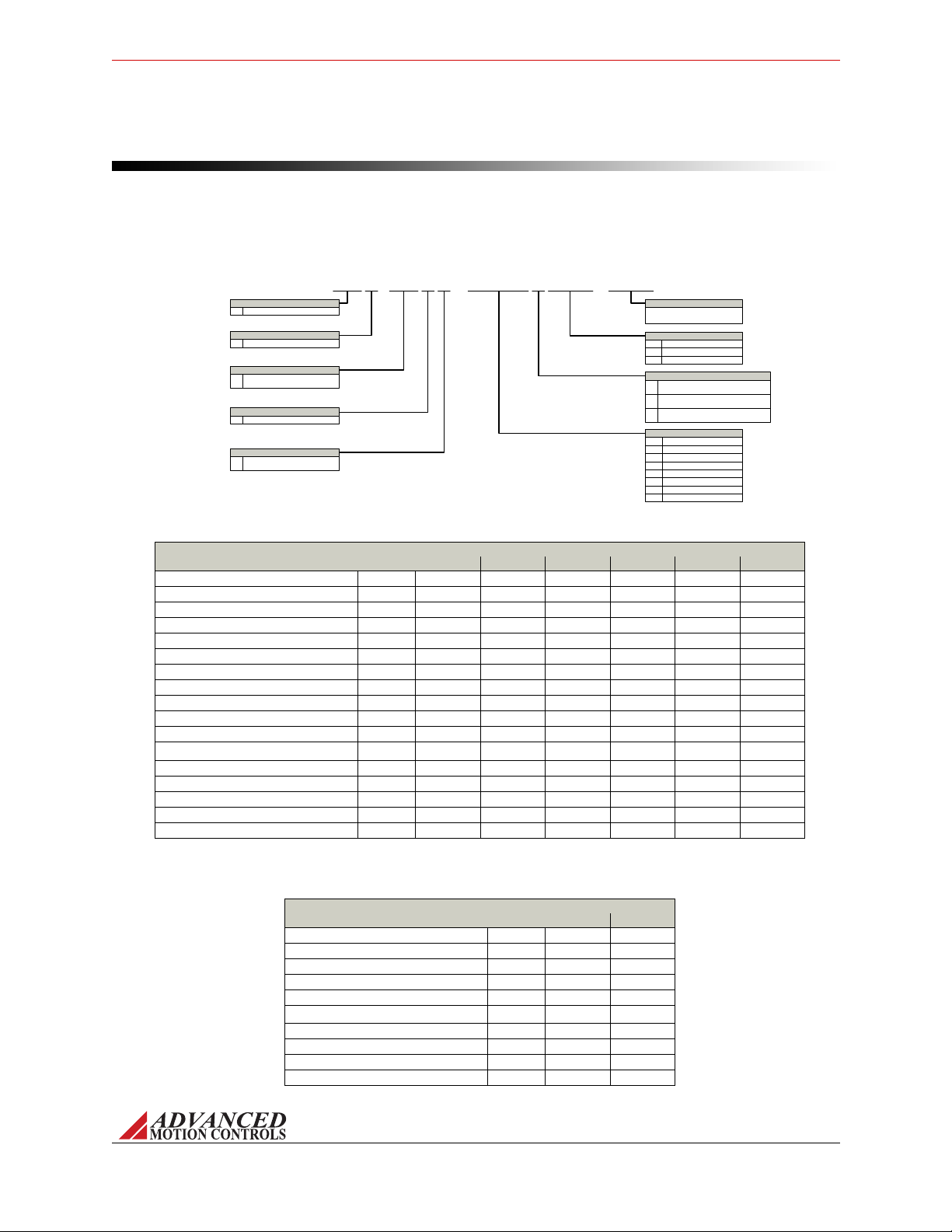
FIGURE 2.1 DPP Part Numbering Structure
C-
Drive Series
DigiFlex Performance
Communication
Command Inputs
PPD INA U 060 A 004Example:
DP
POWERLINK / Modbus TCP / EthernetP
Analog (±10V)
No Step & Direction
AN
Digital I/O
Isolated (24V)I
Motor Feedback
Max DC Bus Voltage (VDC)
400400
AC Input
+24VDC User Logic Supply Required
A
15015
-
Code used to identify customer
specials
Universal (Halls, Inc. Enc, Abs. Enc,
1Vp-p Sin/Cos Enc.)
U030 (800V models only)030
60 (800V models only)060
AC Input Single Phase Only
+24VDC User Logic Supply Required
S
Power and Logic Supply
Peak Current (A0 to Peak)
Customer Special
80080
DC Input
Both Logic Supply Options (Internal or User)
B
20020
40040
100100
60C060
800800
100C100
MNDGDPIN-06 5
Products and System Requirements / Products Covered
2.2 Products Covered
The products covered in this manual adhere to the following part numbering structure.
However, additional features and/or options are readily available for OEM’s with sufficient
ordering volume. Feel free to contact ADVANCED Motion Controls for further information.
TABLE 2.1 Power Specifications - AC Power Modules
Power Specifications
Description Units 015S400 040A400 C060A400 C100A400 030A800 060A800
Rated Voltage VAC(VDC) 240 (339) 240 (339) 240 (339) 240 (339) 480 (678) 480 (678)
AC Supply Voltage Range VAC 100-240 100-240 200-240 200-240 200-480 200-480
AC Supply Minimum VAC 90 90 180 180 180 180
AC Supply Maximum VAC 264 264 264 264 528 528
AC Input Phases -133333
AC Supply Frequency Hz 50-60 50-60 50-60 50-60 50-60 50-60
DC Supply Voltage Range VDC 127-373 127-373 255-373 255-373 255-747 255-747
DC Bus Over Voltage Limit VDC 394 394 420 420 850 850
DC Bus Under Voltage Limit VDC 55 55 205 205 230 230
Maximum Peak Output Current A (Arms) 15 (10.6) 40 (28.3) 60 (42.4) 100 (70.7) 30 (21.2) 60 (42.4)
Maximum Continuous Output Current A (Arms) 7.5 (7.5) 20 (20) 30 (30) 50 (50) 15 (10.6) 30 (21.2)
Max. Continuous Output Power @ Rated Voltage1W2415 6441 9662 16103 6830 13650
Max. Continuous Power Dissipation @ Rated Voltage W127 339 509 848 360 720
Internal Bus Capacitance μF540 660 1120 1120 330 330
PWM Switching Frequency kHz 20 20 14 10 10 10
External Shunt Resistor Minimum Resistance Ω25 25 20 20 note 2 40
Minimum Load Inductance (Line-To-Line) μH600 600 600 600 3000 3000
1. P = (DC Rated Voltage) * (Cont. RMS Current) * 0.95
2. Contact factory before using an external shunt resistor with this power module
TABLE 2.2 Power Specifications - DC Power Modules
Power Specifications
Description Units 020B080 100B080
DC Supply Voltage Range VDC 20-80 20-80
DC Bus Over Voltage Limit VDC 88 88
DC Bus Under Voltage Limit VDC 17 17
Maximum Peak Output Current A (Arms) 20 (14.1) 100 (70.73)
Maximum Continuous Output Current A (Arms) 10 (10) 60 (60)
Max. Continuous Output Power @ Rated Voltage1W760 4560
Max. Continuous Power Dissipation @ Rated Voltage W40 240
Internal Bus Capacitance μF33 500
PWM Switching Frequency kHz 20 20
Minimum Load Inductance (Line-To-Line) μH600 250

MNDGDPIN-06 6
Products and System Requirements / Products Covered
TABLE 2.3
Description DPPANIU
Network Communication POWERLINK / Modbus TCP / Ethernet (USB for Configuration)
Command Sources ± 10V Analog, Over the Network, Encoder Following, Sequencing, Indexing, Jogging
Commutation Methods Sinusoidal, Trapezoidal
Control Modes Profile Modes, Cyclic Synchronous Modes, Current, Velocity, Position
Motors Supported Three Phase (Brushless Servo), Single Phase (Brushed Servo, Voice Coil, Inductive Load), Stepper (2- or 3-Phase Closed Loop), AC
Induction (Closed Loop Vector)
Hardware Protection 40+ Configurable Functions, Over Current, Over Temperature (Drive & Motor), Over Voltage, Short Circuit (Phase-Phase & Phase-
Ground), Under Voltage
Programmable Digital I/O 11/7
Programmable Analog I/O 2/0
Primary I/O Logic Level 24 VDC
Control Specifications
TABLE 2.4
Description DPPANIU
Hall Sensors
Incremental Encoder
Auxiliary Incremental Encoder
Absolute Encoder (Hiperface®, EnDat®, BiSS C-Mode)
1Vp-p Sine/Cosine Encoder
Tachometer (10 ±VDC)
±10 VDC Position
Note: Drive will support either Incremental Encoder, Absolute Encoder, or 1Vp-p Sine/Cosine Encoder depending on drive firmware
Feedback Options
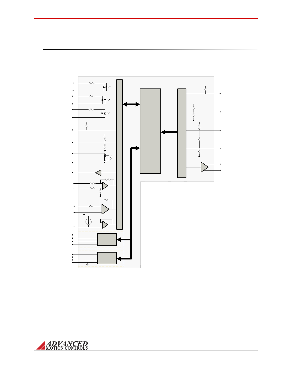
FIGURE 2.2
PAI-1 + (REF+)
PAI-1 – (REF–)
TD+
TD-
I/O Interface
I/O Interface
Drive
Logic
Ethernet
Interface
CONTROL MODULE
10k
+5V
10k
20k
20k 20k
MOTOR THERMISTOR/
SWITCH
DATA-
DATA+
GND
AUX ENC A,B,-)
USB Interface
RD+
RD-
VBUS
AUX ENC A,B,I+
10k
+5V
PDI-1,2,3,4
(GENERAL PURPOSE)
IN COMMON (1-4)
2.5K
PDO-1,2,3,4,5,6
OUT COMMON (1-6)
PDI-5,6,7
(GENERAL PURPOSE)
IN COMMON (5-7)
2.5K
PDI-8,9,10,11
(GENERAL PURPOSE)
IN COMMON (8-11)
2.5K
ENC A,B,I + /
SIN+ / COS+ /
REF MARK+
ENC A,B,I – /
SIN- / COS- /
REF MARK-
HALL A,B,C + /
DATA,CLOCK+
HALL A,B,C – /
DATA,CLOCK-
+5V
+5V
+5V
Motor Feedback
ENC A,B,I + OUT
ENC A,B,I – OUT
PAI-2
SGN GND
33k
HS PDO-7
DPPANIU Control Module
MNDGDPIN-06 7
Products and System Requirements / Products Covered
2.2.1 Control Module
The diagram below shows the general block diagram for the DPPANIU control module. For
complete pinouts, consult the drive’s datasheet.

MNDGDPIN-06 8
Products and System Requirements / Communication Protocol
2.3 Communication Protocol
DPP digital drives offer networking capability through POWERLINK, Modbus TCP or Ethernet
communication. An auxiliary USB port is featured for configuring the drive through
DriveWare.
Ethernet POWERLINK is an open-source real-time industrial Ethernet protocol created by
B&R Automation. POWERLINK expands upon Ethernet according to the IEE 802.3 standard
with a mixed polling and time slicing mechanism. The POWERLINK communication profile is
based on CANopen communication profiles DS301 and DS302. POWERLINK is developed and
maintained by the Ethernet POWERLINK Standardization Group (EPSG). For more detailed
information on POWERLINK communication with DPP drives and a complete list of register
definitions, consult the ADVANCED Motion Controls’ POWERLINK Communication Manual
available for download at www.a-m-c.com.
For more information on POWERLINK visit www.ethernet-powerlink.org.
Modbus is an open standard, master slave system developed for communication between
multiple devices using a single wire. The Modbus protocol uses a defined message structure,
regardless of the physical layer of the network used to communicate. A master device initiate a
"query", and slave devices return a "response", supplying the requested data or taking the
requested action. The query can be made to individual devices or broadcast to all connected
devices. For more detailed information on Modbus TCP communication with DPP drives and a
complete list of register definitions, consult the ADVANCED Motion Controls’ Modbus
Communication Manual available for download at www.a-m-c.com.
The Modbus TCP protocol for ADVANCED Motion Controls’ DPP drives follows the Modbus
Application Protocol Specification V1.1b. More information can be found at www.Modbus-
IDA.org.
MNDGDPIN-06 9
Products and System Requirements / Control Modes
2.4 Control Modes
DPP digital drives operate in a variety of operating modes. The setup and configuration
parameters for these modes are commissioned through DriveWare. See the DriveWare
Software Manual for mode configuration information.
2.4.1 Profile Modes
In Profile Modes, the trajectory is limited by the drive, using the Command Limiter values to
limit the maximum command rate. If the host sends a large command step, the drive spreads
the demand over some period of time to stay equal to or below the maximum defined rate.
Profile Current (Torque) In Current (Torque) Mode, the input command voltage controls the
output current. The drive will adjust the output duty cycle to maintain the commanded output
current. This mode is used to control torque for rotary motors (force for linear motors), but
the motor speed is not controlled. The output current and other parameters can be monitored
in DriveWare through the digital oscilloscope function. DriveWare also offers configuration of
maximum and continuous current limit values.
Profile Velocity In Velocity Mode, the input command voltage controls the motor velocity. This
mode requires the use of a feedback element to provide information to the drive about the
motor velocity. DPC drives allow velocity control with either Hall Sensors, an encoder, a
resolver, or a tachometer as the feedback element. The motor velocity and other parameters
can be monitored in DriveWare through the digital oscilloscope function. The feedback
element being used for velocity control must be specified in DriveWare, which also offers
configuration of velocity limits. See “Feedback Supported” on page 11 for more information on
feedback devices.
Profile Position In Position Mode, the input command voltage controls the actual motor position.
This mode requires the use of a feedback element to provide information to the drive about
the physical motor location. DPC drives allow position control with either an encoder, a
resolver, or ±10V Position feedback. The motor position and other parameters can be
monitored in DriveWare through the digital oscilloscope function. The feedback element being
used for position control must be specified in DriveWare, which also offers configuration of
position limits. See “Feedback Supported” on page 11 for more information on feedback
devices.
2.4.2 Cyclic Synchronous Modes
Cyclic Synchronous Modes give responsibility of trajectory control to the host. The drive
interpolates between command points, defining the rate by dividing the change in command
While in Current (Torque) Mode, the drive will maintain a commanded
torque output to the motor based on the input reference command.
Sudden changes in the motor load may cause the drive to output a high
torque command with little load resistance, causing the motor to spin
rapidly. Therefore, Current (Torque) Mode is recommended for
applications using a digital position controller to maintain system stability.
Note

MNDGDPIN-06 10
Products and System Requirements / Control Modes
by the interpolation time period. This allows the drive to respond smoothly to each step in
command.
Cyclic Synchronous Current In Cyclic Synchronous Current Mode, the drive closes the
current loop. The host is allowed more control by having the ability to instantly add current
feedforward values. This allows for gain compensation in applications with varying loads.
Cyclic Synchronous Velocity In Cyclic Synchronous Velocity Mode, the drive closes two
control loops: velocity and current. The host is allowed more control by having the ability to
instantly add velocity and current feedforward values. This allows for gain compensation in
applications with varying loads.
Cyclic Synchronous Position In Cyclic Synchronous Position Mode, the drive closes three
control loops: position, velocity, and current. The host can send target position, velocity
feedforward, and current feedforward values to the drive. This allows for gain compensation in
applications with varying loads.
2.4.3 Current (Torque)
In Current (Torque) Mode, the input command controls the output current. The drive will
adjust the output duty cycle to maintain the commanded output current. This mode is used to
control torque for rotary motors (force for linear motors), but the motor speed is not
controlled. The output current and other parameters can be monitored within the
configuration software, or externally through network commands.
While in Current (Torque) Mode, the drive will maintain a commanded
torque output to the motor based on the input reference command.
Sudden changes in the motor load may cause the drive to output a high
torque command with little load resistance, causing the motor to spin
rapidly. Therefore, Current (Torque) Mode is recommended for
applications using a digital position controller to maintain system stability.
2.4.4 Velocity
In Velocity Mode, the input command controls the motor velocity. This mode requires the use
of a feedback element to provide information to the drive about the motor velocity. The motor
velocity and other parameters can be monitored within the configuration software, or
externally through network commands. See “Feedback Supported” on page 11 for more
information on velocity feedback devices.
2.4.5 Position
In Position Mode, the input command controls the actual motor position. This mode requires
the use of a feedback element to provide information to the drive about the physical motor
location. The motor position and other parameters can be monitored within the configuration
software, or externally through network commands. See “Feedback Supported” on page 11 for
more information on position feedback devices.
Note

MNDGDPIN-06 11
Products and System Requirements / Feedback Supported
2.5 Feedback Supported
DPP drives feature the ability to support a variety of primary feedback devices by downloading
the appropriate firmware into the drive. Compatible firmware-dependent devices are
Incremental Encoders, Absolute Sin/Cos Encoders (Hiperface®, EnDat®, and BiSS C-Mode),
and 1Vp-p Sin/Cos Encoders. Consult the DriveWare Software Manual for instructions on how
to download firmware into a digital servo drive.
Other supported feedback types that do not require a firmware change are Hall Sensors,
Auxiliary Incremental Encoder, Tachometer, and ±10 VDC Position feedback.
Feedback Polarity The drive compares the feedback signal to the command signal to produce
the required output to the load by continually reducing the error signal to zero. The feedback
element must be connected for negative feedback. Connecting the feedback element for
positive feedback will lead to a motor "run-away" condition. In a case where the feedback
lines are connected to the drive with the wrong polarity, the drive will attempt to correct the
"error signal" by applying more command to the motor. With the wrong feedback polarity, this
will result in a positive feedback run-away condition. The correct feedback polarity will be
determined and configured during commissioning of the drive. Otherwise, to correct this,
either change the order that the feedback lines are connected to the drive, or use DriveWare to
reverse the internal velocity feedback polarity setting.
2.5.1 Incremental Encoder
DPP drive models can utilize incremental encoder feedback for velocity or position control,
with the option of also using the encoder to commutate the motor. The encoder provides
incremental position feedback that can be extrapolated into very precise velocity or position
information. With an encoder being used as the feedback element, the input command
controls the motor velocity or motor position, with the frequency of the encoder pulses closing
the velocity and/or position loop. The encoder signals are read as "pulses" that the drive uses
to essentially keep track of the motor’s speed, position and direction of rotation. Based on the
speed and order in which these pulses are received from the encoder, the drive can interpret
the motor velocity and physical location. The actual motor speed and physical location can be
monitored within the configuration software, or externally through network commands.
Figure 2.3 below represents differential encoder "pulse" signals, showing how dependent on
which signal is read first and at what frequency the "pulses" arrive, the speed and direction of
the motor shaft can be extrapolated. By keeping track of the number of encoder "pulses" with
respect to a known motor "home" position, DPP drives are able to ascertain the actual motor
location.

FIGURE 2.3 Encoder Feedback Signals
Encoder A+
Encoder B+
Encoder A+
Encoder B+
Example 1: Encoder-A precedes Encoder-B. The pulses
arrive at a certain frequency, providing speed and
directional information to the drive.
Example 2: Encoder-B precedes Encoder-A, meaning the
direction is opposite from Example 1. The signal frequency
is also higher, meaning the speed is greater than in
Example 1.
Encoder A-
Encoder B-
Encoder A-
Encoder B-
The high resolution of motor mounted encoders allows for excellent
velocity and position control and smooth motion at all speeds. Encoder
feedback should be used for applications requiring precise and
accurate velocity and position control, and is especially useful in
applications where low-speed smoothness is the objective.
FIGURE 2.4 Sin/Cos Encoder Interpolation
Electrical Degrees
090 180 270 360
1 Vp-p Sin/Cos
Encoder Interpolation
Cos
Sin
0
Volts
1 to 512 lines
per Sin/Cos
cycle
# of Counts per
Sin/Cos cycle = (Interpolation value) x 4
MNDGDPIN-06 12
Products and System Requirements / Feedback Supported
2.5.2 Absolute Encoder
DPP drives support Hiperface®, EnDat® (2.1/2.2 command set), or BiSS C-Mode absolute
encoders for velocity and absolute position feedback. The encoder resolution and other
options can be configured within the drive configuration software. The drive breaks down the
signals from the encoder into individual reference points (counts). For feedback devices that
accept 1 Vp-p signals, the interpolation is configurable in powers of 2 from 1 to 512 lines per
Sin/Cos cycle. The quadrature number of counts per cycle is the interpolation value multiplied
by 4, as shown in Figure 2.4. This allows for very high interpolated encoder resolution (4-2048
counts).
The absolute position feedback eliminates the need for a homing routine
when the drive is powered on.
Note
Note

MNDGDPIN-06 13
Products and System Requirements / Feedback Supported
2.5.3 1Vp-p Sin/Cos Encoder
DPP drives support 1Vp-p Sin/Cos encoders for position and velocity feedback. The drive
breaks down the 1 Vp-p sinusoidal signals from the encoder into individual reference points
(counts). The interpolation is configurable in powers of 2 from 1 to 512 lines per Sin/Cos cycle.
The quadrature number of counts per cycle is the interpolation value multiplied by 4, as shown
in Figure 2.4. This allows for very high interpolated encoder resolution (4-2048 counts per
Sin/Cos cycle).
2.5.4 Hall Sensors
DPP drives can use single-ended or differential Hall Sensors for commutation and/or velocity
control. The Hall Sensors (typically three) are built into the motor to detect the position of the
rotor magnetic field. With Hall Sensors being used as the feedback element, the input
command controls the motor velocity, with the Hall Sensor frequency closing the velocity loop.
Hall velocity mode is not optimized for relatively high or relatively low Hall
frequencies. To determine if Hall velocity mode is right for your
application, contact Applications Engineering.
For more information on using Hall Sensors for trapezoidal commutation, see “Trapezoidal
Commutation” on page 48.
2.5.5 Auxiliary Incremental Encoder
The auxiliary encoder input pins can be used as a command source for encoder following
mode, or as a secondary feedback device input for closing the position loop. The particular
function is configured in the configuration software.
2.5.6 Tachometer (±10 VDC)
DPP drives support the use of a tachometer for velocity feedback. The tachometer measures
the rotary speed of the motor shaft and returns an analog voltage signal to the drive for
velocity control. DPP drives provide a Programmable Analog Input on the motor Feedback
Connector that is available for use with a tachometer. The tachometer signal is limited to ±10
VDC.
2.5.7 ±10 VDC Position
DPP drives accept an analog ±10 VDC Position feedback, typically in the form of a load-
mounted potentiometer. The feedback signal must be conditioned so that the voltage does not
exceed ±10 V, and is connected to the drive through the Programmable Analog Input. In
DriveWare, the connection method that is used must be selected under the Position Loop
Feedback options. See the DriveWare Software Guide for more information.
Note
Table of contents
Popular DC Drive manuals by other brands


Moons'
Moons' MSSTAC6 user manual

Erreka
Erreka ERGOS Series Quick installation and programming guide

PrimoPal
PrimoPal PSR5042 user manual

FALK
FALK Ultramite UB Installation & maintenance instructions

Antal
Antal LD700/24 Installation and user guide

Rockwell Automation
Rockwell Automation Allen-Bradley PowerFlex 4M installation instructions

Trinamic
Trinamic PANdrive PD-1140 Hardware manual

Rockwell Automation
Rockwell Automation Allen-Bradley PowerFlex 755 installation instructions

Johnson Controls
Johnson Controls PENN VFD68 installation instructions

KLEE
KLEE Drive MS Series manual

Nidec
Nidec E300 Series Installation and System Design Guide

Siemens
Siemens SINAMICS S120 Function manual