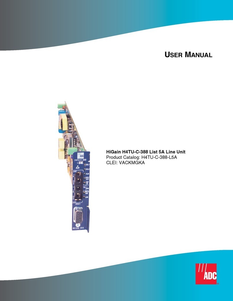
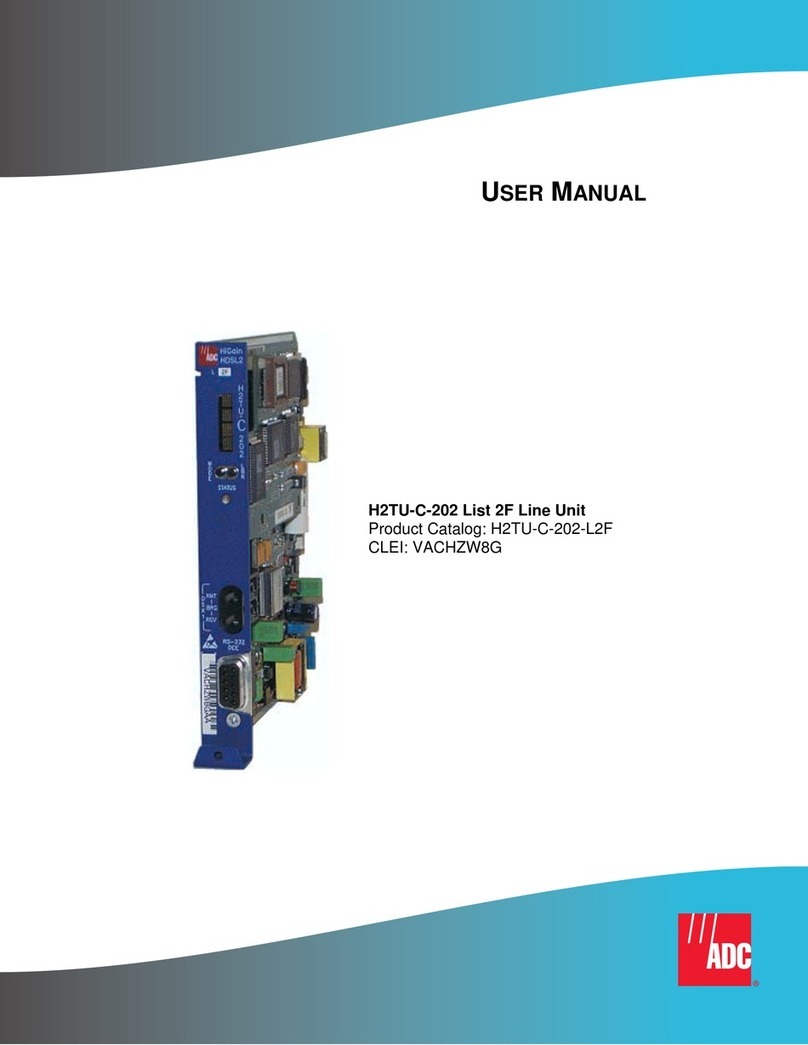
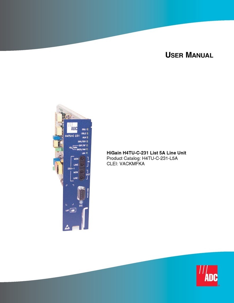
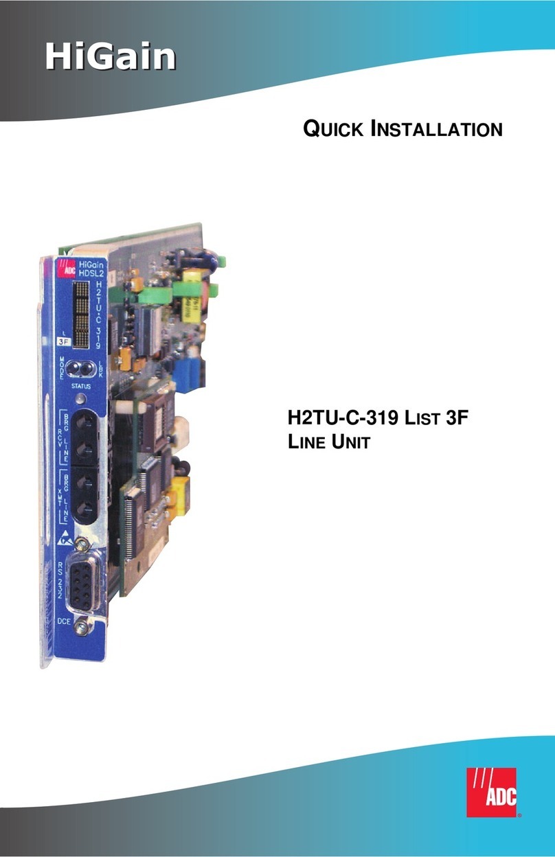
ADC HiGain HLU-319 Original operating instructions

HiGain
HiGain
FCC Class A Compliance
This equipment has been tested and found to comply with the limits for a Class A digital device, pursuant
to Part 15 of the FCC Rules. These limits are designed to provide reasonable protection against harmful
interference when the equipment is operated in a commercial environment. This equipment generates,
uses, and can radiate radio frequency energy and, if not installed and used in accordance with the
instruction manual, may cause harmful interference to radio communications. Operation of this
equipment in a residential area is likely to cause harmful interference in which case the user will be
required to correct the interference at his own expense.
Limited Warranty
Product warranty is determined by your service agreement. Contact your sales representative or
Customer Service for details.
Modifications
Any changes or modifications made to this device that are not expressly approved by ADC DSL
Systems, Inc. voids the user's warranty.
All wiring external to the products should follow the provisions of the current edition of the National
Electrical Code.
Standards Compliance
This equipment has been tested and verified to comply with the applicable sections of the following
safety standards:
GR 63-CORE - Network Equipment-Building System (NEBS) Requirements
GR 1089-CORE - Electromagnetic Compatibility and Electrical Safety
Binational standard, UL-1950/CSA-C22.2 No. 950-95: Safety of Information Technology
Equipment
Trademark Information
ADC is a registered trademark of ADC Telecommunications, Inc. HiGain is a registered trademark of
ADC DSL Systems, Inc. Other product names mentioned in this installation guide are used for
identification purposes only and may be trademarks or registered trademarks of their respective
companies.
Copyright Information
© 1999 ADC DSL Systems, Inc. All rights reserved. Information contained in this document is company
private to ADC DSL Systems, Inc., and shall not be modified, used, copied, reproduced or disclosed in
whole or in part without the written consent of ADC.
ADC DSL Systems, Inc.
14402 Franklin Avenue
Tustin, CA 92780-7013
Tel: 714.832.9922
Fax: 714.832.9924
Technical Assistance
Tel: 800.638.0031
Tel: 714.730.3222
Fax: 714.730.2400
DNV C ertificatio n, Inc.
REGISTERED FIRM
ISO 9001/TL 9000
HLU-319 LIST 5D
The HiGain®Line Unit HLU-319 List 5D is the Central Office (CO) side of a
repeaterless, T1 transmission system. When used in conjunction with a HiGain
Remote Unit (HRU), the system provides 1.544 Mbps transmission on two
unconditioned copper pairs over the full Carrier Service Area (CSA) range. The CSA
includes loops up to 12,000 feet of 24 AWG or 9,000 feet of 26 AWG wire, including
bridgedtaps.Thislineunit canbe usedin applicationswithor withoutHiGainDoubler
Units (HDUs).
FEATURES
SPECIFICATIONS
•Front panel status LED and four-character
status display •Payload (PL) or HiGain (HG) loopback source
identification
•Ultra low wander •Reduced power consumption
•Five-span range with four doublers
(60 kft, 24 AWG) •Low line-power option (-135 V) for circuits
with a single doubler
•Selectable power feed modes •Bit Error Rate (BER) alarm options
•Loss of Signal (LOS)/Alarm Indicator Signal
(AIS) payload alarm option •Bipolar Violation Transparency (BPVT)
options
•Provisioning screens for inventory and
troubleshooting •Four line-power spans (three doublers and
one remote unit)
•Remote Provisioning •HDSL grounded loop detection
•HRU loopback screen
Operating Temperature -40 °F to +149 °F (-40 °C to + 65 °C)
Operating Humidity 5% to 95% non-condensing
HDSL Span Voltage -140 to ±112 Vdc
Mounting STS (3192) high-density shelf
HDSL Line Code 784 kbps 2B1Q
HDSL Output +13.5 dBm ±0.5 dB, 135 Ω
Maximum Provisioning Loss 35 dB at 196 KHz, 135 Ω
DS1 Line Rate 1.544 Mbps ±200 bps
DS1 Line Format Alternate Mark Inversion (AMI) or Bipolar with
8-Zero Substitution (B8ZS)
DS1 Frame Format Extended SuperFrame (ESF), SuperFrame (SF) or
THRU
DSX-1 Pulse Output 6 V pk-pk, pre-equalized for 0 to 655 feet of ABAM
cable
DSX-1 Input Level +1.5 to -7.5 dB DSX
INSTALLATION
To install the HLU, slide the line unit into the card guides for the desired slot, then
push the unit back until it seats firmly in the backplane card-edge connector.
POWER-UP SEQUENCE
When the HLU powers up, the four-character display illuminates and reports status
messages. If the HLU is not communicating with the next span device, the following
events occur:
1Alarm and diagnostic messages are displayed (see the Front Panel Alarm
Messages and Front Panel Diagnostic Messages tables inside), followed by the
SELF TEST message.
2The Status LED turns yellow, indicating it has entered self-test mode.
If the HLU is communicating with the next span device, the following occurs:
1The Status LED flashes green while acquiring each device in the system, and
turns a steady green when the entire system is operating without any alarms.
2The four-character display reports margin (signal-to-noise ratio) readings and
insertion loss.
3If the status LED is not solid green, the display reports alarm conditions (see the
Front Panel Alarm Messages table inside).
PROVISIONING
1Access the Maintenance Terminal screens by pressing the several
times.
aSet the date and time (select Set Clock from the Main Menu).
bSet the circuit IDs (select View System Inventory).
2Access the Systems Settings selection on the Main Menu to change the default
settings of any system parameters.
3Access the View Troubleshooting screen to view a graphical analysis of any
potential system problems.
4When the HLU has been successfully installed and provisioned, clear the Span
Status, Performance Data, Performance History, and Alarm History screens to
ensure accurate data and alarm reporting.
SPACEBAR
HLU-319 LIST 5D
LINE UNIT
QUICK INSTALLATION
´,/^¶5.¨
1215625
August 27, 1999
Product Catalog: 150-1140-54
CLEI: T1L2B30A
Document: 350-319-154-06

HiGain
HiGain
FCC Class A Compliance
This equipment has been tested and found to comply with the limits for a Class A digital device, pursuant
to Part 15 of the FCC Rules. These limits are designed to provide reasonable protection against harmful
interference when the equipment is operated in a commercial environment. This equipment generates,
uses, and can radiate radio frequency energy and, if not installed and used in accordance with the
instruction manual, may cause harmful interference to radio communications. Operation of this
equipment in a residential area is likely to cause harmful interference in which case the user will be
required to correct the interference at his own expense.
Limited Warranty
Product warranty is determined by your service agreement. Contact your sales representative or
Customer Service for details.
Modifications
Any changes or modifications made to this device that are not expressly approved by ADC DSL
Systems, Inc. voids the user's warranty.
All wiring external to the products should follow the provisions of the current edition of the National
Electrical Code.
Standards Compliance
This equipment has been tested and verified to comply with the applicable sections of the following
safety standards:
GR 63-CORE - Network Equipment-Building System (NEBS) Requirements
GR 1089-CORE - Electromagnetic Compatibility and Electrical Safety
Binational standard, UL-1950/CSA-C22.2 No. 950-95: Safety of Information Technology
Equipment
Trademark Information
ADC is a registered trademark of ADC Telecommunications, Inc. HiGain is a registered trademark of
ADC DSL Systems, Inc. Other product names mentioned in this installation guide are used for
identification purposes only and may be trademarks or registered trademarks of their respective
companies.
Copyright Information
© 1999 ADC DSL Systems, Inc. All rights reserved. Information contained in this document is company
private to ADC DSL Systems, Inc., and shall not be modified, used, copied, reproduced or disclosed in
whole or in part without the written consent of ADC.
ADC DSL Systems, Inc.
14402 Franklin Avenue
Tustin, CA 92780-7013
Tel: 714.832.9922
Fax: 714.832.9924
Technical Assistance
Tel: 800.638.0031
Tel: 714.730.3222
Fax: 714.730.2400
DNV C ertificatio n, Inc.
REGISTERED FIRM
ISO 9001/TL 9000
HLU-319 LIST 5D
The HiGain®Line Unit HLU-319 List 5D is the Central Office (CO) side of a
repeaterless, T1 transmission system. When used in conjunction with a HiGain
Remote Unit (HRU), the system provides 1.544 Mbps transmission on two
unconditioned copper pairs over the full Carrier Service Area (CSA) range. The CSA
includes loops up to 12,000 feet of 24 AWG or 9,000 feet of 26 AWG wire, including
bridgedtaps.Thislineunit canbe usedin applicationswithor withoutHiGainDoubler
Units (HDUs).
FEATURES
SPECIFICATIONS
•Front panel status LED and four-character
status display •Payload (PL) or HiGain (HG) loopback source
identification
•Ultra low wander •Reduced power consumption
•Five-span range with four doublers
(60 kft, 24 AWG) •Low line-power option (-135 V) for circuits
with a single doubler
•Selectable power feed modes •Bit Error Rate (BER) alarm options
•Loss of Signal (LOS)/Alarm Indicator Signal
(AIS) payload alarm option •Bipolar Violation Transparency (BPVT)
options
•Provisioning screens for inventory and
troubleshooting •Four line-power spans (three doublers and
one remote unit)
•Remote Provisioning •HDSL grounded loop detection
•HRU loopback screen
Operating Temperature -40 °F to +149 °F (-40 °C to + 65 °C)
Operating Humidity 5% to 95% non-condensing
HDSL Span Voltage -140 to ±112 Vdc
Mounting STS (3192) high-density shelf
HDSL Line Code 784 kbps 2B1Q
HDSL Output +13.5 dBm ±0.5 dB, 135 Ω
Maximum Provisioning Loss 35 dB at 196 KHz, 135 Ω
DS1 Line Rate 1.544 Mbps ±200 bps
DS1 Line Format Alternate Mark Inversion (AMI) or Bipolar with
8-Zero Substitution (B8ZS)
DS1 Frame Format Extended SuperFrame (ESF), SuperFrame (SF) or
THRU
DSX-1 Pulse Output 6 V pk-pk, pre-equalized for 0 to 655 feet of ABAM
cable
DSX-1 Input Level +1.5 to -7.5 dB DSX
INSTALLATION
To install the HLU, slide the line unit into the card guides for the desired slot, then
push the unit back until it seats firmly in the backplane card-edge connector.
POWER-UP SEQUENCE
When the HLU powers up, the four-character display illuminates and reports status
messages. If the HLU is not communicating with the next span device, the following
events occur:
1Alarm and diagnostic messages are displayed (see the Front Panel Alarm
Messages and Front Panel Diagnostic Messages tables inside), followed by the
SELF TEST message.
2The Status LED turns yellow, indicating it has entered self-test mode.
If the HLU is communicating with the next span device, the following occurs:
1The Status LED flashes green while acquiring each device in the system, and
turns a steady green when the entire system is operating without any alarms.
2The four-character display reports margin (signal-to-noise ratio) readings and
insertion loss.
3If the status LED is not solid green, the display reports alarm conditions (see the
Front Panel Alarm Messages table inside).
PROVISIONING
1Access the Maintenance Terminal screens by pressing the several
times.
aSet the date and time (select Set Clock from the Main Menu).
bSet the circuit IDs (select View System Inventory).
2Access the Systems Settings selection on the Main Menu to change the default
settings of any system parameters.
3Access the View Troubleshooting screen to view a graphical analysis of any
potential system problems.
4When the HLU has been successfully installed and provisioned, clear the Span
Status, Performance Data, Performance History, and Alarm History screens to
ensure accurate data and alarm reporting.
SPACEBAR
HLU-319 LIST 5D
LINE UNIT
QUICK INSTALLATION
´,/^¶5.¨
1215625
August 27, 1999
Product Catalog: 150-1140-54
CLEI: T1L2B30A
Document: 350-319-154-06

LOOPBACK TESTING
Initiate loopback testing from the HiGain maintenance menus or use the MODE and SEL
buttons. The hexidecimal inband codes shown below can be sent by a test set.
S
E
L
M
O
D
E
HLU-319
HiGain HD
L5D
R
C
V
B
R
G
M
A
R
G
I
N
(dB)
B
R
G
X
M
T
L
I
N
E
L
I
N
E
R
S
2
3
2
SETUP
STATUS
Four-character display
System option buttons (for manual setting of
system parameters)
DSX-1 test access jacks
CLEI and ECI
bar code label
List number
(HLU version
number)
Displays status, provisioning, and
alarm messages. See the
table below for a list of message
descriptions.
Front Panel Alarm Messages
Use MODE and SEL to manually modify user options,
initiate loopbacks, and display DSX-1 line parameters.
Connect standard test equipment.
SPAN
BRG
Provides splitting jack access to
(XMT) and from (RCV) the HDSL span
at the DSX-1 interface.
Provides non-intrusive bridging jack
access to (XMT) and from (RCV) the
HDSL span at the DSX-1 interface.
Allows monitoring of the T1 payloads.
Craft port provisioning
To access all system maintenance, provisioning
and performance screens, connect a standard
9-pin terminal cable between the serial port on a PC
and the HLU craft port.
1
2
3
4
Press the MODE button for 2 seconds and release.
The front panel alternately displays the first
system parameter and its current setting.
Press SEL to step through all possible settings for
the displayed parameter.
Press MODE to update the parameter and advance
to the next parameter.
After scrolling through all the parameters, press SEL
to confirm changes when prompted with a CONF YES
message, or press MODE to cancel all changes.
1200-9600 baud
8 data bits
No parity
1 stop bit
Hardware flow control:NONE
Terminal emulation
software:VT-100
Status LED
Reports the following conditions:
Self Test is in process or
a CREM or NLOC loopback
is in effect.
Green LED Normal operation
Flashing Green LED HDSL acquisition
Red LED Fuse alarm
Flashing Red LED System alarm
Yellow LED
FlashingYellow LED System is in ARM mode.
3
4
5
6
C
D
E
F
H7
8
J
9
K
10
L
Ground
HDSL1-T HDSL1-R
HDSL2-R1HDSL2-T1
Systemalarm** Mgmt.bus
Frameground -48Vdc BAT
Fusealarm*
Factory burn-in
(Donot use)
1
A
DSX-1TX-T DSX-1TX-R
2
B
DSX-1 RCV-T1 DSX-1RCV-R1
Fuse alarm
System alarm
Normal = Floating (+5 to -60 Vdc maximum)
Activated = +5 Vdc, 10mA maximum
Normal = Floating (0 to -60 Vdc maximum)
Activated = -48 Vdc, 10mA maximum
*
**
Card-edge Connector Front Panel
Modem settings:
A5LB Special Loopback Commands
Inband Code
11000. . . ARMING or NI LPBK (2-in-5 arming code)
11100. . . IR LPDN or DISARM (3-5 disamarming code)
D3D3 IOR LPBK (NLOC and CREM 230-232 bit errors and 229-231 bit errors)
C741 ILR-1 LPBK (NDU1 and CDU1 10 bit errors)
C754 LR-20 LPBK (NDU2 and CDU2 200 bit errors)
C743 ILR-3 LPBK (NDU3 and CDU3 30 bit errors)
C744 ILR-4 LPBK (NDU4 and CDU4 40 bit errors)
C742 ILR-2 LPBK (NREM and CLOC 20 bit errors)
For more detailed information about the maintenance terminal
screens, provisioning, and loopback mode testing, refer to the
HLU-319 List 5D technical practice, document number 150-319-154-xx.
Copies of this publication or the technical practice can bedownloaded
from the ADC website at
www.adc.com
. To order a hard copy, please
contact your sales representative.
Front Panel Alarm Messages
Message Description
ALRM A system alarm condition is in effect.
ACO A system alarm has been retired to an alarm cutoff condition by pressing the SEL button.
LOSW Indicates that one of the HDSL loops has lost sync.
LLOS Indicates that no signal is detected at the DSX-1 input to the HLU.
RLOS Indicates that no signal is detected at the DSX-1 input to the HRU.
MAL1 or MAL2 The margin on HDSL Loop 1 or Loop 2 has dropped below the threshold (1 to 15 dB)
setting.
BER A system Bit Error Rate alarm is in effect.
NONE No alarm present.
Front Panel Diagnostic Messages
Message Description
1=xx or 2=yy Indicates the power of the received HDSL signal on each loop relative to noise. Any value
of 06 or greater is adequate for reliable system operation.
ACQ1 or ACQ2 The multiplexers of the HLU and the HRU or the first doubler are trying to establish
synchronization over Loop 1 or Loop 2 of Span 1.
AnL1 or AnL2 The multiplexers of the two devices on Span nare trying to establish synchronization with
each other on Loop 1 or Loop 2, where nis the number of the span.
BAD RT? The HLU is not receiving any response from the HRU.
CODE xxxx The line code setting, where xxxx is Alternate Mark Inversion (AMI) or Bipolar with 8-Zero
Substitution (B8ZS).
FERR Framing bit error occurred at HLU DSX-1 input.
FRM xxxx Determines the type of frame pattern being received from the DSX-1 where xxxx is SF,
ESF, THRU, or NONE.
H1ES or H2ES HLU HDSL Loop 1 or Loop 2 CRC error.
nHDU Number (n) of doublers in the circuit.
INSL, then xxDB The maximum Insertion Loss message (INSL) appears followed by xxDB, where xx is the
maximum insertion in dB of all spans and loops.
LBPV A local bipolar violation has been received at the DSX-1 input to the HLU.
MNGD The HLU is under control of the HMU-319 Network Management Unit.
PWRF GND One of the HDSL loops has been grounded.
PWRF ON Indicates that the HDSL loops are not grounded or shorted.
PWRF OFF HDSL span power has been turned off.
PWRF SHRT Indicates a short between the two HDSL pairs or the inability of the HRU to communicate
with the HLU.
SELF TEST The HLU is in a self-test mode. This occurs every power on/off cycle.
SIG1 or SIG2 The transceivers of the HLU and HRU or first doubler are trying to establish contact with
each other on Loop 1 or Loop 2 of Span 1.
SnL1 or SnL2 The transceivers of the two devices on Span nare trying to establish contact with each
other on Loop 1 or Loop 2, where nis the number of the span.
System Settings
Display Code Description (default values in bold)
EQL Sets the equalizer to DSX-1 for: 0 (0 to 133 ft.), 133 (133 to 266 ft.), 266 (266 to 399 ft.),
399 (399 to 533 ft.), 533 (533 to 655 ft.)
LBPK Enables (ENA) or disables (DIS) all inband SMJK loopback commands
PWRF DIS = disables HDSL powering
LOW = HDSL line voltage is -140 V max.
AUTO = automatically switches between -140 V for nondoubler applications and ±112 V
for doubler applications)
HIGH = ±112 V for all applications
BERT NONE = prevents generation of a system alarm due to excessive BER
1E-6 or 1E-7 = alarm activates when BER threshold exceeds 10-6 or 10-7
LBTO Loopback timeout = NONE, 20, 60, 120 minutes
ALM Enables (ENA) or disables (DIS) the alarm relay
LNCD Line code = places the HLU and HRU in B8ZS or AMI mode
SAIS Enables (ENA) or disables (DIS) transmission of AIS signal during NREM/SMJK loopbacks
MARG 0 to 15 dB (can only be set through a maintenance terminal connected to the craft port);
the default is 4dB
RDA Enables (ENA) or disables (DIS) alarm indications due to remote DS1 LOS at HRU input
ALMP Enables a line to output an (AIS) payload of all ones or an (LOS) condition at its DS1 ports
for LOSW, DS1, LOS and margin alarms
RTPV Enables (ENA) provisioning at the remote (when remotely logged in) or disables (DIS)
provisioning at the remote
BPVT Enables (ENA) or disables (DIS) bipolar violation transparency (conversion of input DS1
BPVs and HDSL CRC errors into DS1 BPVs at the distant end’s DS1 output port)

HiGain
HiGain
FCC Class A Compliance
This equipment has been tested and found to comply with the limits for a Class A digital device, pursuant
to Part 15 of the FCC Rules. These limits are designed to provide reasonable protection against harmful
interference when the equipment is operated in a commercial environment. This equipment generates,
uses, and can radiate radio frequency energy and, if not installed and used in accordance with the
instruction manual, may cause harmful interference to radio communications. Operation of this
equipment in a residential area is likely to cause harmful interference in which case the user will be
required to correct the interference at his own expense.
Limited Warranty
Product warranty is determined by your service agreement. Contact your sales representative or
Customer Service for details.
Modifications
Any changes or modifications made to this device that are not expressly approved by ADC DSL
Systems, Inc. voids the user's warranty.
All wiring external to the products should follow the provisions of the current edition of the National
Electrical Code.
Standards Compliance
This equipment has been tested and verified to comply with the applicable sections of the following
safety standards:
GR 63-CORE - Network Equipment-Building System (NEBS) Requirements
GR 1089-CORE - Electromagnetic Compatibility and Electrical Safety
Binational standard, UL-1950/CSA-C22.2 No. 950-95: Safety of Information Technology
Equipment
Trademark Information
ADC is a registered trademark of ADC Telecommunications, Inc. HiGain is a registered trademark of
ADC DSL Systems, Inc. Other product names mentioned in this installation guide are used for
identification purposes only and may be trademarks or registered trademarks of their respective
companies.
Copyright Information
© 1999 ADC DSL Systems, Inc. All rights reserved. Information contained in this document is company
private to ADC DSL Systems, Inc., and shall not be modified, used, copied, reproduced or disclosed in
whole or in part without the written consent of ADC.
ADC DSL Systems, Inc.
14402 Franklin Avenue
Tustin, CA 92780-7013
Tel: 714.832.9922
Fax: 714.832.9924
Technical Assistance
Tel: 800.638.0031
Tel: 714.730.3222
Fax: 714.730.2400
DNV C ertificatio n, Inc.
REGISTERED FIRM
ISO 9001/TL 9000
HLU-319 LIST 5D
The HiGain®Line Unit HLU-319 List 5D is the Central Office (CO) side of a
repeaterless, T1 transmission system. When used in conjunction with a HiGain
Remote Unit (HRU), the system provides 1.544 Mbps transmission on two
unconditioned copper pairs over the full Carrier Service Area (CSA) range. The CSA
includes loops up to 12,000 feet of 24 AWG or 9,000 feet of 26 AWG wire, including
bridgedtaps.Thislineunit canbe usedin applicationswithor withoutHiGainDoubler
Units (HDUs).
FEATURES
SPECIFICATIONS
•Front panel status LED and four-character
status display •Payload (PL) or HiGain (HG) loopback source
identification
•Ultra low wander •Reduced power consumption
•Five-span range with four doublers
(60 kft, 24 AWG) •Low line-power option (-135 V) for circuits
with a single doubler
•Selectable power feed modes •Bit Error Rate (BER) alarm options
•Loss of Signal (LOS)/Alarm Indicator Signal
(AIS) payload alarm option •Bipolar Violation Transparency (BPVT)
options
•Provisioning screens for inventory and
troubleshooting •Four line-power spans (three doublers and
one remote unit)
•Remote Provisioning •HDSL grounded loop detection
•HRU loopback screen
Operating Temperature -40 °F to +149 °F (-40 °C to + 65 °C)
Operating Humidity 5% to 95% non-condensing
HDSL Span Voltage -140 to ±112 Vdc
Mounting STS (3192) high-density shelf
HDSL Line Code 784 kbps 2B1Q
HDSL Output +13.5 dBm ±0.5 dB, 135 Ω
Maximum Provisioning Loss 35 dB at 196 KHz, 135 Ω
DS1 Line Rate 1.544 Mbps ±200 bps
DS1 Line Format Alternate Mark Inversion (AMI) or Bipolar with
8-Zero Substitution (B8ZS)
DS1 Frame Format Extended SuperFrame (ESF), SuperFrame (SF) or
THRU
DSX-1 Pulse Output 6 V pk-pk, pre-equalized for 0 to 655 feet of ABAM
cable
DSX-1 Input Level +1.5 to -7.5 dB DSX
INSTALLATION
To install the HLU, slide the line unit into the card guides for the desired slot, then
push the unit back until it seats firmly in the backplane card-edge connector.
POWER-UP SEQUENCE
When the HLU powers up, the four-character display illuminates and reports status
messages. If the HLU is not communicating with the next span device, the following
events occur:
1Alarm and diagnostic messages are displayed (see the Front Panel Alarm
Messages and Front Panel Diagnostic Messages tables inside), followed by the
SELF TEST message.
2The Status LED turns yellow, indicating it has entered self-test mode.
If the HLU is communicating with the next span device, the following occurs:
1The Status LED flashes green while acquiring each device in the system, and
turns a steady green when the entire system is operating without any alarms.
2The four-character display reports margin (signal-to-noise ratio) readings and
insertion loss.
3If the status LED is not solid green, the display reports alarm conditions (see the
Front Panel Alarm Messages table inside).
PROVISIONING
1Access the Maintenance Terminal screens by pressing the several
times.
aSet the date and time (select Set Clock from the Main Menu).
bSet the circuit IDs (select View System Inventory).
2Access the Systems Settings selection on the Main Menu to change the default
settings of any system parameters.
3Access the View Troubleshooting screen to view a graphical analysis of any
potential system problems.
4When the HLU has been successfully installed and provisioned, clear the Span
Status, Performance Data, Performance History, and Alarm History screens to
ensure accurate data and alarm reporting.
SPACEBAR
HLU-319 LIST 5D
LINE UNIT
QUICK INSTALLATION
´,/^¶5.¨
1215625
August 27, 1999
Product Catalog: 150-1140-54
CLEI: T1L2B30A
Document: 350-319-154-06
Table of contents
Other ADC Computer Hardware manuals
Popular Computer Hardware manuals by other brands

Steffes
Steffes 1023065R Installation

Rainbow Technologies
Rainbow Technologies QPCF operating instructions

STEINWAY LYNGDORF
STEINWAY LYNGDORF Steinway & Sons P100 owner's manual

Iomega
Iomega Clik! drive 40 quick start guide

Thermaltake
Thermaltake Floe RC240 manual

SK Pang Electronics
SK Pang Electronics PiCAN FD user guide