ADDER ALIF1000 User manual

AdderLink Infinity
Quick Start Guide
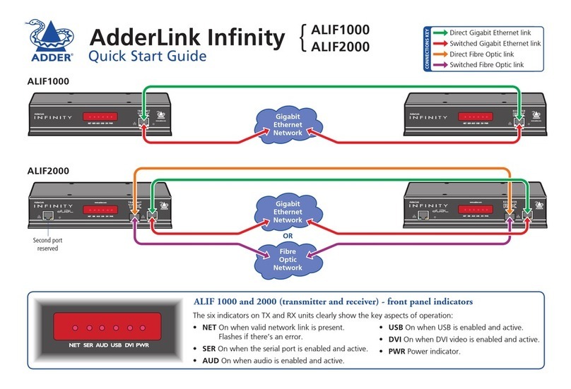
ALIF 1000 and 2000 (transmitter and receiver) - front panel indicators
NET SER AUDUSB DV IPWR
The six indicators on TX and RX units clearly show the key aspects of operation:
NET On when valid network link is present.
Flashes if there’s an error.
SER On when the serial port is enabled and active.
AUD On when audio is enabled and active.
USB On when USB is enabled and active.
DVI On when DVI video is enabled and active.
PWR Power indicator.
ALIF1000
ALIF2000
{
CONNECTIONS KEY
Direct Gigabit Ethernet link
Switched Gigabit Ethernet link
Direct Fibre Optic link
Switched Fibre Optic link
www.adder.com
AdderLink
RECEIVER
NETSER AUDUSB DVIPWR
www.adder.com
AdderLink
NET SERAUD USBDVI PWR
TRANSMIT
Gigabit
Ethernet
Network
ALIF1000
www.adder.com
AdderLink
NET SERAUD USBDVI PWR
TRANSMIT www.adder.com
AdderLink
NET SER AUDUSB DVIPWR
RECEIVER
Gigabit
Ethernet
Network
Fibre
Optic
Network
OR
ALIF2000
Second port
reserved

Configuration
on each unit (see below).
to specify their network address details. This can be done by
altered.
Note: For basic one-to-one installations, the factory default
addresses may be acceptable for immediate use within your
network without the need to use a configuration utility or change
their values: TX unit (169.254.1.33), RX unit (169.254.1.32).
Manual factory reset
socket.
of three seconds to indicate a successful reset operation.
APower input
B
E
F
CUSB port(s)
DVideo input
GVideo output
INDOOR
USE ONLY OPTIONS AUX
LINE IN/ LINE OUT
DVI-D
12
USER CONSOLE
5V
2.5A
ON
21
MIC IN
ALIF1000 receiver - rear panel
AC E
BF
G
ALIF1000 transmitter - rear panel
AUX
LINE IN
LINE OUT
COMPUTER
ON
21
INDOOR
USE ONLY OPTIONS
12
5V
2.5A
DVI-D
ACDE
BF
AUX
COMPUTER
ON
21
INDOOR
USE ONLY OPTIONS
12
DVI-D-1
5V 2.5A
DVI-D-2
IN OUT
ACDE
B
F
ALIF2000 transmitter - rear panel
D
12
DVI-D-2
5V 4A
DVI-D-1
ALIF2000 receiver - rear panel
ACGE
B
F
G
1
2
units use
12.5W
power
adapters.
units use
20W
power
adapters.

Infinity browser-based configuration utility
To access the browser-based configuration utility
http://169.254.1.33 or http://169.254.1.33
TX units169.254.1.33
RX units169.254.1.32
Note: Where the address of a unit is not known, perform a
manual factory reset (see left) to restore the default address.
TX (transmitter) unit configuration
Configuring
the RX unit
Video Configuration
RX (receiver) unit configuration

RX (receiver) unit configuration
operation: either Unicast or Multicast
Configuring the RX unit
1 Display the System Configuration
locations (click the blue arrow to reveal the separate addresses).
Multicast Settings section.
The address that you enter will be used by the RX unit to
Other manuals for ALIF1000
1
This manual suits for next models
1
Other ADDER Transmitter manuals
Popular Transmitter manuals by other brands
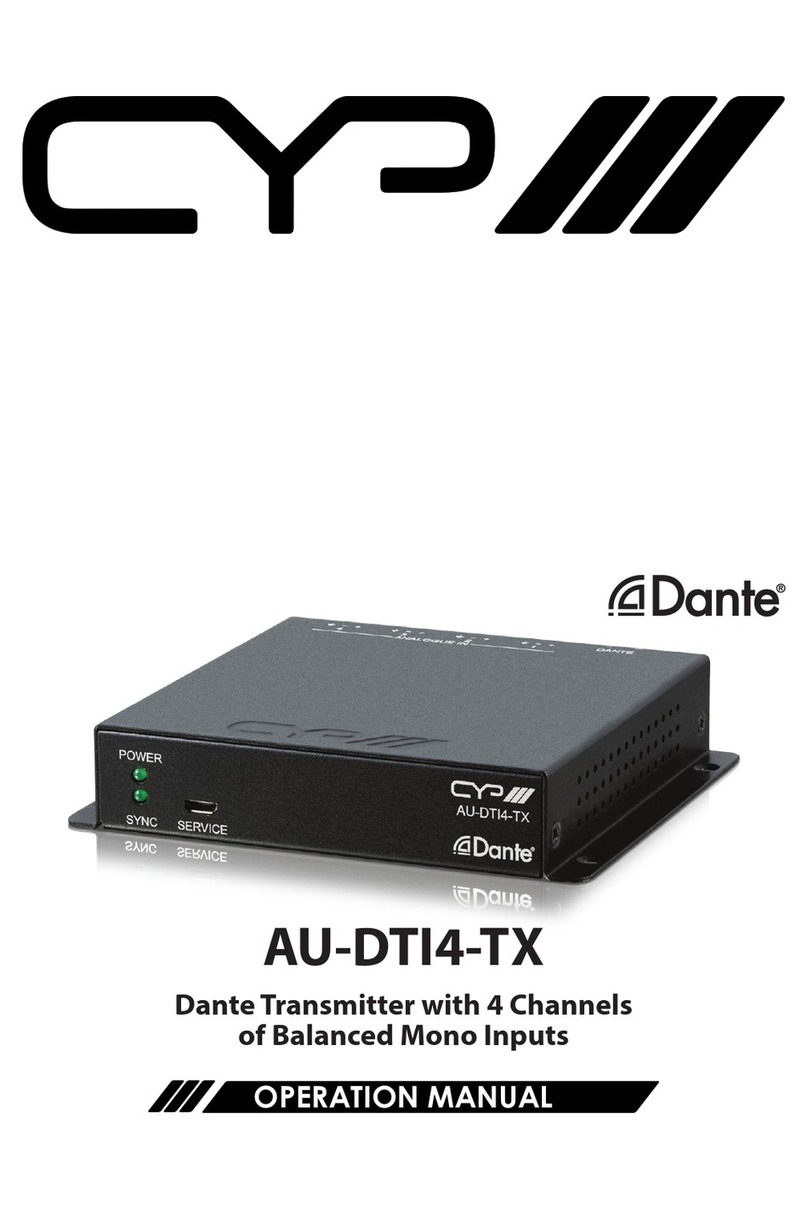
CYP
CYP Dante AU-DTI4-TX Operation manual

Marconi
Marconi PN1A Installing and operating instructions

Abilia
Abilia Gewa IR-1SP Micro manual

RC System
RC System SENSMART 2000 user manual

Altinex
Altinex VGA to CAT-5 Transmitter Card MT103-115 user guide
Camille Bauer
Camille Bauer KINAX 3W2 operating instructions
Wikk Wireless
Wikk Wireless SWTRAN915 Programming instructions

Viatran
Viatran 510 Installation data manual

PR electronics
PR electronics PRetop 5334 manual
NEC
NEC DTU-70 instruction manual

MultiDyne
MultiDyne HD-3500 series instruction manual

Mil-Ram Technology, Inc.
Mil-Ram Technology, Inc. TA-2102 instruction manual
