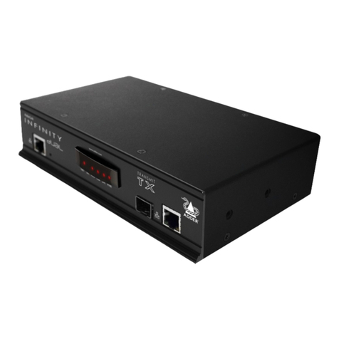
ADDER ALIF1000 User manual

AdderLink Infinity
Quick Start Guide
ALIF 1000 and 2000 (transmitter and receiver) - front panel indicators
NET SER AUDUSB DV IPWR
The six indicators on TX and RX units clearly show the key aspects of operation:
• NET On when valid network link is present.
Flashes if there’s an error.
• SER On when the serial port is enabled and active.
• AUD On when audio is enabled and active.
• USB On when USB is enabled and active.
• DVI On when DVI video is enabled and active.
• PWR Power indicator.
ALIF1000
ALIF2000
{
CONNECTIONS KEY
Direct Gigabit Ethernet link
Switched Gigabit Ethernet link
Direct Fibre Optic link
Switched Fibre Optic link
www.adder.com
AdderLink
RECEIVER
NETSER AUDUSB DVIPWR
www.adder.com
AdderLink
NET SERAUD USBDVI PWR
TRANSMIT
Gigabit
Ethernet
Network
ALIF1000
www.adder.com
AdderLink
NET SERAUD USBDVI PWR
TRANSMIT www.adder.com
AdderLink
NET SER AUDUSB DVIPWR
RECEIVER
Gigabit
Ethernet
Network
Fibre
Optic
Network
OR
ALIF2000
Second port
reserved

Configuration
• IfALIFTXandRXunitsaredirectlyconnected,noconguration
actionisrequired,providedthattheyhavetheirfactorydefault
settingsinplace.Ifthestandardsettingshavebeenchangedina
previousinstallation,youmerelyneedtoperformafactoryreset
on each unit (see below).
• WhereALIFunitsareconnectedvianetworklinks,youwillneed
to specify their network address details. This can be done by
connectingacomputersystemtemporarilytoeachALIFunit
andusingtheInnitybrowser-basedcongurationutility.This
congurationutilityalsoallowsnumerousothersettingstobe
altered.
Note: For basic one-to-one installations, the factory default
addresses may be acceptable for immediate use within your
network without the need to use a configuration utility or change
their values: TX unit (169.254.1.33), RX unit (169.254.1.32).
Manual factory reset
UsetoreturnaTXorRXunittoitsdefaultconguration.
1 RemovepowerfromtheALIFunit.
2 Locatethesmallholeonthefrontpanel:ALIF1000-Nexttothe
onlyEthernetsocket;ALIF2000-Nexttotheleft-handEthernet
socket.
3 Pushanarrowimplement(e.g.astraightened-outpaperclip)into
theholeandholditin.Meanwhile,powerontheunit.
Afteraroundeightseconds,whenthefactoryresethas
completed,veofthefrontpanelindicatorswillashforaperiod
of three seconds to indicate a successful reset operation.
4 Removetheimplementandthenre-applypowertostarttheunit
initsdefaultconguration.
APower input
B Congswitches
E Audiolinein/out
F Serialcongport
CUSB port(s)
DVideo input
GVideo output
INDOOR
USE ONLY OPTIONS AUX
LINE IN/ LINE OUT
DVI-D
12
USER CONSOLE
5V
2.5A
ON
21
MIC IN
ALIF1000 receiver - rear panel
AC E
BF
G
ALIF1000 transmitter - rear panel
AUX
LINE IN
LINE OUT
COMPUTER
ON
21
INDOOR
USE ONLY OPTIONS
12
5V
2.5A
DVI-D
ACDE
BF
AUX
COMPUTER
ON
21
INDOOR
USE ONLY OPTIONS
12
DVI-D-1
5V 2.5A
DVI-D-2
IN OUT
ACDE
B
F
ALIF2000 transmitter - rear panel
D
12
DVI-D-2
5V 4A
DVI-D-1
ALIF2000 receiver - rear panel
ACGE
B
F
G
1
2
Note:
ALIF1000
units use
12.5W
power
adapters.
Note:
ALIF2000
units use
20W
power
adapters.

Infinity browser-based configuration utility
Tousethebrowser-basedcongurationutility,linkacomputervia
anetworkswitchtotheALIFunit(GigabitEthernetisnotessential
forthecongurationstage).Thiscongurationutilityallowsyouto
performallofthefollowingfunctions:
• View/edittheIPnetworkaddressandnetmask,
• CongureseparateIPnetworkaddressesforvideo,audioandUSB,
• Conguremulticastsettings(onRXunits),
• Congurevideobandwidthsettings(onTXunits),
• Viewthecurrentvideooutput(onTXunits),
• Performarmwareupgrade,
• Performafactoryreset.
To access the browser-based configuration utility
1 ConnecttheInnityunitandacomputerviaanetwork.
2 RunawebbrowseronyourcomputerandentertheIPaddressof
theInnityunit,e.g.http://169.254.1.33 or http://169.254.1.33
Thedefaultsettingsareasfollows:
• TX units-IPaddress:169.254.1.33Netmask:255.255.255.0
• RX units-IPaddress:169.254.1.32Netmask:255.255.255.0
Note: Where the address of a unit is not known, perform a
manual factory reset (see left) to restore the default address.
TX (transmitter) unit configuration
IntheALIFsystem,themostimportantcongurationdetailsare
dictatedbyRXunits.Thus,theTXunitsetupisconcernedonlywith
threemainfactors:
• ItsIPaddress,
• Thedatastreamstoenable/disable,and
• Videosignaloptimization.
ThemethodtosettheIPaddressanddatastreamsisexactlythe
sameasfortheRXunit-pleasefollowsteps1to3ofConfiguring
the RX unitsectionontherearpage.InaGigabitEthernetnetwork
withsufcientbandwidth,changestotheVideo Configurationpage
shouldnotbenecessary.Ifadjustmentsarerequired,pleaseseethe
AdderLinkInnityfulluserguidefordetails.
RX (receiver) unit configuration
Pleaseseetherearpage.

AdderTechnologyLimited,
SaxonWay,BarHill,
Cambridge,CB238SL,
UnitedKingdom
Tel:+44(0)1954780044
Fax:+44(0)1954780081
www.adder.com
©2011AdderTechnologyLimited•Release1.1b
Alltrademarksareacknowledged.MAN-ALIF-QUICK
AdderCorporation,
350RMerrimacStreet,
Newburyport,
MA01950,
UnitedStatesofAmerica
Tel:+1-888-932-3337
Fax:+1-888-275-1117
AdderAsiaPacic,
8BurnRoad,
#04-10,Trivex,
369977,Singapore
Tel:+6562885767
Fax:+6596161283
IMPORTANT:PleaseseethefullInnityuser
guideforsafety,warrantyandregulatory
information.Thefulluserguideissupplied
ontheCD-ROMwiththeunitandisalso
availablefromwww.adder.com.
RX (receiver) unit configuration
IntheALIFsystem,theRXunitdetermineswhereandhowdata
signalsaresent(andreceived)bytheTXunit.Althoughnumerous
ALIFtopologies(one-to-one,one-to-many,many-to-one,etc.)are
madepossible,theyarealldependentontwounderlyingmodesof
operation: either Unicast or Multicasttransmission.Wheremulticast
transmissionisnotinvokedforvideoand/oraudiodata,operation
willbeautomaticallyservedbyunicastnetworktransmission
technologies.
Configuring the RX unit
1 Display the System ConfigurationpageoftheInnitybrowser-
basedcongurationutility.
2 EnsurethattheIPaddressandnetmaskforthisRXunitarecorrect.
TheSystemIPAddresssetherewillbesenttotheTXunitasthe
destinationfortransmitteddata(wheninunicastmode).
3 Checkthatthedatastreams(VideoTX,AudioTX/RXandUSB
TX/RX)areenabled(ticked)ordisabled(unticked)asappropriate.
TherearesimilaroptionswithintheInnityTXunitconguration
anditisimportantthatthesettingsinbothunitsarethesame.
4 IntheRemoteUnitSettingssection,entertheIPaddressforthe
TXunitthatwillbesupplyingthevideo,audioandUSBdata
streams.Mostoftenallthreestreamsaresuppliedbythesame
TXunit,however,itispossibletoreceivethemfromdifferent
locations (click the blue arrow to reveal the separate addresses).
5 ForinstallationsthatwillincludemorethanoneRXunit,youalso
needtoconguretheMulticast Settings section.
TheVideoandAudiosectionsareconguredinthesameway:
• TicktheEnableMulticastVideo/EnableMulticastAudiobox.
• Next,enteranappropriateMulticastAddressfortheVideo/
Audiodatastream(s).TheIPaddressesbetween224.0.0.0
and239.255.255.255arespecicallyreservedbynetworksfor
multicastoperations.
The address that you enter will be used by the RX unit to
‘listen-in’onthedatastreamfromtheTXunit.ThissameIP
addressneedstobesetoneveryRXunitthatwillsimilarly
receivethedatastream.Thevideoandaudiomulticast
addressescanbethesameordifferent,asrequired.
• ClicktheUpdateNowbuttontosave.
RepeattheIPaddressingandmulticastcongurationstepsforall
RXunitsthatwillbepartoftheone-to-manyinstallation.
Formostinstallations,thesuccessfulimplementationofthese
congurationstepswillresultinacorrectlyworkingsystem.
Other manuals for ALIF1000
1
This manual suits for next models
1
Other ADDER Transmitter manuals
