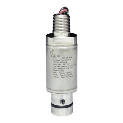
PRODUCT OVERVIEW
NOTE: All information contained in this document is representative of a standard Model 510. If the product you ordered has special
requirements or modi�ications, refer to the Laser Marked information on the product and your purchase order for possible
alteration to the product's con�iguration. Failure to verify product con�iguration before installation may cause permanent product
damage, and in most cases, void the manufacturer's product warranty. If you are unsure or have questions about your product,
please contact our Application Engineers for assistance. Remove and retain all instruction manuals and performance certi�icates
that are shipped with the product. These documents provide important information on the product's calibration, operation, safety
precautions, recommended maintenance, re-calibration requirements, repair service instructions and warranty information. These
documents are updated from time to time as changes to the product occur and should be reviewed at receipt so that proper and safe
installation can occur.
DESCRIPTION
The Viatran Model 510 is a pressure transmitter designed speci�ically for oil �ield service applications. This transmitter provides
a 4-20 mA signal output proportional to pressure. The Hammer Union pressure connection and low-pro�ile design make it ideal
for use at the well site. The �ield calibration feature makes the Viatran 510 Series a leader in oil �ield pressure instrumentation.
GENERAL REQUIREMENTS & CAUTIONS
Note: This is only a partial list. Please refer to the Installation Data section of this manual for speci�ic requirements.
1. All electrical & pressure connections should be compatible with the model speci�ications as outlined in the Installation Data
section of this manual.
2. Installation should occur only after electrical (input power) and line pressure is veri�ied as being off and at zero.
3. The product's internal electrical circuitry is isolated from case ground. It is not recommended that the case or ground of the
unit be connected to the input, output or calibrate pins of the product or wiring system. Ground loops and line noise will
affect the product's performance and will in most cases cause internal electrical failure.
4. All products should be protected from direct or continued exposure to �luids at the electrical connection. It is recommended
that for products installed in areas where the potential for contamination at the electrical connection is possible, protective
measures be taken to eliminate possible deterioration of the product's electrical connection and corrosion that will impede
product performance.
5. At no time should an object be inserted into the pressure port or pressed against the sensing area to de�lect the sensor (to
test or simulate pressure), as on some models, permanent damage to the sensing diaphragm may occur.
6. Never - Remove the transmitter when it is under pressure, if it is hot, or if it exposes noxious gases.
HANDLING
Although there are variations within the series of sensors, the nominal weight of the assembly is about 5.5 lbs. This is of
signi�icant size and a handle is available to facilitate handling. High surface temperatures canremain in place and the unit
should be checked before removing the unit from service if it was operated at high temperatures. Suitable gloves are
recommended for handling the unit under those conditions. There are no sharp edges associated with the instrument.
INSTALLATION REQUIREMENTS & CAUTIONS
1. To comply with CE requirements for electromagnetic compatibility, the transmitter case must be earthed by the ground lug at
the connector.
2. It is recommended that the connector cover be placed on the product's connector after each use. Simple cleaning and
removal of foreign material in the connector will increase the life and operation of the
product.
3. The carrying handle and connector cover should be used when the product is being handled
or transported between locations.
4. Installation of the unit is accomplished by placing the pressure transmitter into the Hammer
Union pressure �itting and securing the unit by tightening the Hammer Union Nut (Fig. 1)
over both the unit and pressure �itting. Once installed, check for leaks and adjust as
necessary.
