AudioBahn A4002J User manual

PLEASE READ THIS MANUAL
BEFORE OPERATING THIS UNIT.
RETAIN FOR FUTURE REFERENCE.
A2002J/A4002J/A8002J/A4004J
A6004J/A8000J/A16000J/A5005J
OWNER’S MANUAL

To bring the product to market that excites the consumer through sound and
vision from an orientation of integrity and customer service. We make you look as
good as you sound. We strive to take car audio to an extreme the world has never
seen, and a world that never stops evolving.
Audiobahn was established in 1997 with one long-term goal in mind, “Build
it Bigger, Badder, & Better, and the people will take notice!” We back this statement
with an engineering team that has brought home several Innovations, Design &
Engineering Showcase Awards, and a marketing team from around the world that
spends countless hours developing our no compromise products to satisfy the most
discriminating enthusiasts.
Our global manufacturing facilities feature ISO9002 ratings (the highest level
of quality control awarded in the electronics manufacturing industry), fully robotic as-
sembly lines and a state of the art, California based R & D laboratory.
Our Technical Department and entire staff look to strive above and beyond
the rest of the pack by going that extra mile to help you out. Whether you happen to
be a veteran competitor, or a beginner car audio enthusiast who does not know a
voice coil from a spider. We are all her to help you get the best system you can with
what you have.
Judge for yourself, and remember what it’s all about, “If it’s not Bigger, Bad-
der & Better, it’s not Audiobahn.” If audio is your life, Audiobahn is the brand for you!
We make you look as good as you sound. People never stop trying to get the best
product, so we will never stop making it.
The Audiobahn Way

Introduction______________________________________________________3
Features and Specications_________________________________________4
Control and Functions 5-16
A2002J_________________________________________________________5
A4002J_________________________________________________________6
A8002J_________________________________________________________7
A4004J / A6004J_________________________________________________8
A8000J / A16000J________________________________________________9
A5005J________________________________________________________10
High Level Input Wiring 17 - 18
A2002J / A4002J / A8002J / A8000J / A16000J / A4004J / A6004J__________17
A5005J________________________________________________________18
Planning / Mounting Your System__________________________________19
Wiring Diagram_________________________________________________20 - 23
A2002J / A4002J / A8002J_________________________________________20
A4004J / A6004J________________________________________________21 - 22
A8000J / A16000J________________________________________________22
A8000J / A16000J________________________________________________23
Adjustments and Tunning_________________________________________24
Trouble Shooting________________________________________________25
Warning / Disclaimer_____________________________________________26
Warranty_______________________________________________________27 - 28
Notes__________________________________________________________29 - 30
TABLE OF CONTENTS

Dear Customer,
Congratulations on your purchase of the worlds nest brand of car audio products. Here at
Audiobahn Inc. we are devoted to making our musical reproduction the vert best, and we
are pleased you have chosen our product. Through years of engineering expertise, hand
craftsmanship, and critical testing procedures, we have created a wide range of products
that reproduce music with all the clarity and richness you deserve.
For maximum performance we recommend you have your Audiobahn product installed by
an Authorized Audiobahn Dealer, as we provide specialized training through our Audiobahn
Installer Training Programs. Please read your warranty, keep your receipt, and original
carton for possible future use.
To get a free brochure on Audiobahn products in the US call (714) 452-1476 or e-mail us at
WARNING
Continuous exposure to sound pressure levels over 100dB may cause permanent
hearing loss. High powered autosound systems may produce sound pressure levels
well over 135dB. Need we say more! Use common sense.
If after reading this manual you still have questions regarding your product, we recom-
mend that you see your nearest Audiobahn Dealer. A list of Authorized Audiobahn
Dealers can be found on our web page. If you need further assistance, feel free to call
us at (714) 452-1476 and ask for the Technical Department. Be sure to have the model
number, date of purchase, and invoice number available when you call.
The model number can be located on the outside of the carton. Record this in the space
provided below along with the date of purchase. It is a good idea to keep your receipt
with this as you will need it in the case of needing a warranty, repair service or ex-
change.
Date of Purchase: _____________________Model Number:___________________
INTRODUCTION
3

A2002J :
75 watts x 2 @ 4 Ohms RMS power
A4002J :
250 watts x 2 @ 2 Ohms RMS power
A8002J :
500 x 2 @ 2 Ohms RMS power
A4004J :
50 watts x 4 @ 4 Ohms RMS power
A6004J :
200 watts x 4 @ 2 Ohms RMS power
A8000J :
500 watts x 1 @ 4 Ohms RMS Power
11 1/16" x 2 1/8" x 6 13/16"
11 1/16" x 2 1/8" x 8 3/8"
11 1/16" x 2 1/8" x 11 7/8"
11 1/16" x 2 1/8" x 9 1/8"
11 1/16" x 2 1/8" x 9 7/8"
11 1/16" x 2 1/8" x 11 7/8"
281 x 55x 173.0mm
281 x 55 x 212.7mm
281 x 55 x 282.6mm
281 x 55 x 231.8mm
281 x 55 x 250.8mm
281 x 55 x 301.6mm
,
remote
&
(A2002J : 25A x 1) (A4002J : 40A x 1) (A8002J : 30A x 2) (A4004J : 20A x 2)
(A6004J : 25A x 2) (A8000J : 30A x 2) (A16000J : 40A x 2) (A5005J : 30A x 3)
A2002J (W x H x D)
A4002J (W x H x D)
A8002J (W x H x D)
A4004J (W x H x D)
A6004J (W x H x D)
A8000J (W x H x D)
A16000J (W x H x D)
A5005J (W x H x D) :
100 watts x 2 @ 2 Ohms RMS power
125 watts x 2 @ 4 Ohms RMS power
500 watts x 1 @ 4 Ohms RMS power
250 watts x 2 @ 4 Ohms RMS power
100 watts x 4 @ 2 Ohms RMS power
1000 watts x 1 @ 2 Ohms RMS power
1000 watts x 1 @ 4 Ohms RMS power
300 watts x 1 @ 4 Ohms RMS power 200 watts x 2 @ 4 Ohms RMS power
100 watts x 4 @ 4 Ohms RMS power
400 watts x 2 @ 4 Ohms RMS power
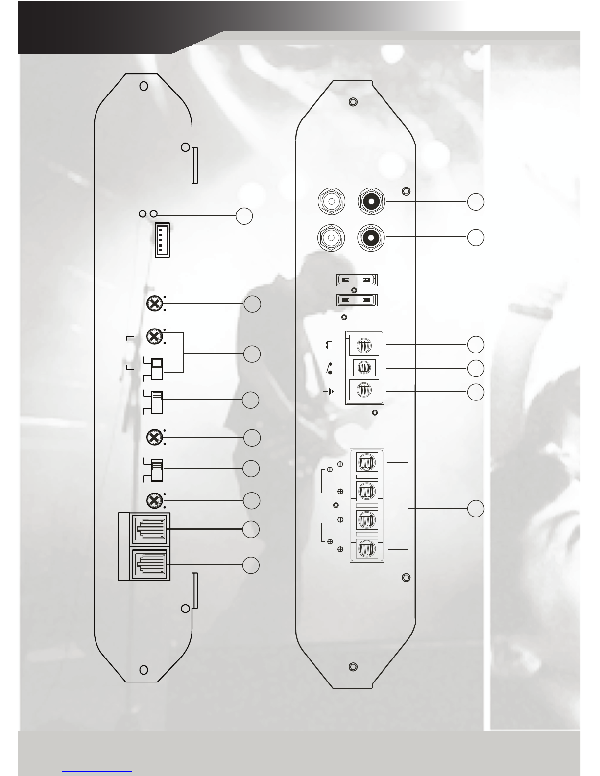
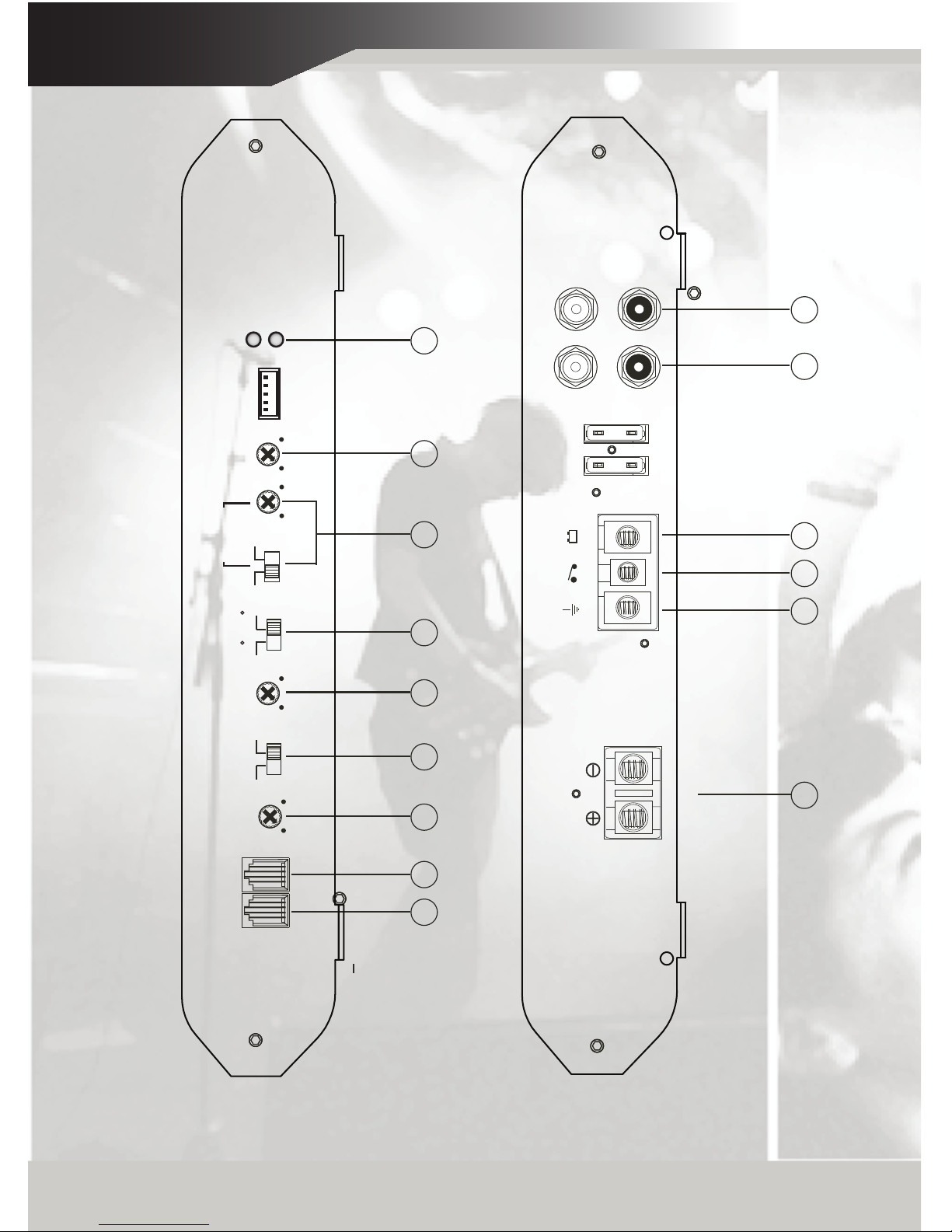
Input Sensitivity 200mV - 8V
On-Board Digital Volt Meter
A16000J :
900 watts x 1 @ 4 Ohms RMS Power
1800 watts x 1 @ 2 Ohms RMS power
11 1/16" x 2 1/8" x 15 5/8" 281 x 55 x 398mm
281 x 55 x 439mm
A5005J :
100 wattsx 4 + 500 x 1 @ 2 Ohms RMS power
50 watts x 4 + 250 x 1 @ 4 Ohms RMS power
200 watts x 2 @ 500 x 1 @ 2 Ohms RMS power
11 1/16" x 2 1/8" x 17 1/4”
FEATURES & SPECIFICATIONS
4

A2002J REAR
A2002J FRONT
1 2 3 4 10 11
LCH
BRIDGED
SPEAKER
RCH
BATT
GND REM
POWER LOW INPUT LINE OUT
L
RR
L
FUSE
13 7 6 14
8 9 5 16
SEAN AND WILSON ROCK
PROTECTION
POWER
HIGH INPUT
LEVEL
MIN MAX20 50
BOOST
BASS
HPF
50 750
X-OVER
LPF
50 120
ON OFFON OFF
LPF HPF FULL
SONIC
SUB
+ L - G- R +
DVM REMOTE
12
CONTROLS & FUNCTIONS
5

A4002J REAR
A4002J FRONT
1 2 3 4 10 11
L
LINE OUT
LOW INPUT
L
RR
FUSE
POWER
REMGND BATT
SPEAKER
BRIDGED
LCH RCH
13 7 6 14
8 9 5 16
SEAN AND WILSON ROCK
POWER
PROTECTION
HIGH INPUT
LEVEL
MIN MAX50 120 50 750 20 50
SUB SONIC
ON OFFON OFF
BASS
BOOST
HPFLPF X-OVER
LPF HPF FULL
REMOTEDVM
+ L - G- R +
12
CONTROLS & FUNCTIONS
6

SPEAKER
BRIDGED
LCH RCH
POWER
GND REM BATT
L
R
LOW INPUT LINE OUT
L
R
1 2 3 4 10 11
A8002J REAR
A8002J FRONT
12 13 7 6 14
8 9 5 16
SEAN AND WILSON ROCK
POWER
PROTECTION
REMOTEDVM
+ L - G- R +
SUB
SONIC
LPF HPF FULL ON OFF ON OFF
50 120
LPF X-OVER
50 750
HPFBASS
BOOST
20 50 MIN MAX
LEVEL
HIGH INPUT
FUSE
CONTROLS & FUNCTIONS
7

POWER
GND REM BATT
1
2
1
2
LOW INPUTLINE OUT
3
4
1 2 3 4 10
11
A4004J/A6004J REAR
A4004J/A6004J FRONT
CH1 CH2 CH3 CH4
CH1 CH2 CH3 CH4
CH1 CH2 CH3 CH4
BRIDGED BRIDGED
7 6 14
8 9 5
16
SEAN AND WILSON ROCK
1+ 2- G 3- 4+
HIGH INPUT
POWER
PROTECTION
DVM REMOTE
LPF HPF FULL
X-OVER
LPF HPFBOOST
BASS
ON OFF ON OFF
SUB SONIC
20 5050 75050 120 MIN MAX
LEVEL
20 50 MIN MAX
ON OFFON OFF
50 120 50 750
CH3/4
LPF HPF FULL
CH1/2
12 13
FUSE
CONTROLS & FUNCTIONS
8

LPF X-OVER BASS
BOOST SUB SONIC LEVEL HIGH INPUT
+ L - G - R -
POWER
PROTECTION
50 120 20 50 MIN MAX
0dB 18dB
1312 7 6 14 9 5 16
SEAN AND WILSON ROCK
SPEAKER
POWER
GND REM BATT
L
R
LOW INPUT LINE OUT
L
R
1 2 3 4 10 11
A8000J/A16000J REAR
A8000J/A16000J FRONT
LPF FULL ON OFF
PHASE
SHIFT
15
180 0
REMOTEDVM
FUSE
CONTROLS & FUNCTIONS
9

12 13
16
SEAN AND WILSON ROCK
1 2 3 4
10
10
11
A5005J REAR
A5005J FRONT
5
8
9
5
68 6
14 7 56
CONTROLS & FUNCTIONS
10

L R
A2002J
A4002J
A8002J
1. Speaker Terminals
CH1 CH2 CH3 CH4
BridgedBridged
CH1 CH2 CH3 CH4
A4004J
A6004J
Speaker
A8000J
A16000J
These chrome plated connectors can accept from 16 to 8 gauge wire. Be careful to observe proper polarity when
connecting the cables
2. B - Terminal (Chassis ground)
REM BATTGND
POWER
A2002J
A4002J
A8002J
A4004J
A6004J
A8000J
A16000J
To avoid unwanted ignition noise caused by ground loops, it is essential that the amplifier be grounded to a
clean, bare, metal surface of the vehicles chassis.
Note: GROUND WIRE SHOULD NOT BE EXTENDED MORE THAN 3 FT. (1 METER)
SPEAKER
Bridged
CONTROLS & FUNCTIONS
11

REM BATTGND
POWER
3. Remote Turn-On Input
A2002J
A4002J
A8002J
A4004J
A6004J
A8000J
A16000J
REM BATTGND
POWER
To remote or power antenna output of car stereo. This amplifier is turned "ON" remotely when the vehicle's stereo
is turned "ON".
Note: IF YOUR RADIO DOES NOT HAVE +12 VOLT OUTPUT LEAD WHEN THE RADIO IS TURNED ON, THE
"REMOTE" TERMINAL ON THE AMPLIFIER CAN BE CONNECTED TO THE VEHICLE'S ACCESSORY
CIRCUIT THAT IS LIVE WHEN THE KEY (IGNITION) IS "ON".
4. B+ Terminal (Battery Positive)
5. Input Sensitivity Adjustment
A2002J
A4002J
A8002J
A4004J
A6004J
A8000J
A16000J
Due to the power requirements of the amplifier, this connection should be made directly to the positive (+)
terminal of the battery. For a safety measure, install an in-line fuse holder (not included) as close to the battery
positive (+) as possible with an apmere rating not to exceed the total value of fuses in the amp.
MIN MAX
MIN MAX
MIN MAX A2002J
A4002J
A8002J
A8000J
A16000J
A4004J
A6004J
This control adjusts the amplifier's sensitivity to match the signal strength coming from the source unit. Input
sensitivity is variable from 200 Millivolts to 8 volts. Clockwise increases sensitivity. Counterclockwise decreases
sensitivity. THE KNOB IS NOT A VOLUME CONTROL. A lower signal level will require increased sensitivity for
full power. A higher signal will require decreased sensitivity.
CONTROLS & FUNCTIONS
12

A2002J
A4002J
A8002J
A4004J
A6004J
A5005J
A2002J
A4002J
A8002J
A8000J
A5005J
A16000J
A8000J
A5005J
A16000J
A4004J
A6004J
A5005J
A2002J
A4002J
A8002J
A4004J
A6004J
50 150
50 150
50 150
CONTROLS & FUNCTIONS
13

A2002J
A4002J
A8002J
A8000J
A5005J
A16000J
A4004J
A6004J
A5005J
5
A5005J
CONTROLS & FUNCTIONS
14

12. DVM (Digital Volt Meter Input) Fig 1
15. Phase Shift Switch
DVM REMOTE
12. DVM (Digital Volt Meter Input) Fig 1
DVM REMOTE
14. Bass Boost Switch and Variable
BASS
BOOST
ON OFF
BASS
BOOST
ON OFF
0180
Phase
Shaft
o o
ON OFF
Remote Control for Digital Display Voltmeter: Optional
Bass Boost Control (MIN / MAX) : Optional
Bass Boost Switch: ON and OFF Bass Boost Variable: 0dB - 18dB @ 45Hz
PHASE SHIFT SWITCH (0 AND 180 DEGREES): Allows you to change the phase of your subwoofer from 0
and 180 degrees to help compensate for timing differences between drivers.
o
A4004J
A6004J
A2002J
A4002J
A8002J
A8000J
A16000J
A8000J
A5005J
A16000J
A8000J
A16000J
BASS
BOOST
0 18dB
CONTROLS & FUNCTIONS
15

16. LED indicator (Status)
POWER
PROTECT
-PWR (Power) : This BLUE LED will illuminate when the amplifier is turned "ON". If it fails to illuminate, check the power
connections to the amplifier and fuses.
- PROT (Protection) : The amplifier protection circuitry will disable the amplifier if input overload, short circuit, or extremely
high temperature conditions are detected. When the protection mode is in operation, the LED indicator on the side
panel will be illuminated, indicating the amplifier has gone into a self-preservation mode.
If you observe that the protection LED is lit, please check the system carefully to determine what has caused the
protection circuit to engage. The amplifier shut down due to a thermal overload condition, please allow it to cool
down before restarting. If the amplifier shut down because of an input overload or short circuit, be sure to repair these
conditions before attempting to power up the amplifier again.
Fig 1.
LINECODE
Fig 2.
LINECODE
MIN MAX
Optional Remote Bass Boost Control
Optional Remote Digital Volt Meter
CONTROLS & FUNCTIONS
16

HIGH LEVEL INPUT WIRING
17

HIGH LEVEL INPUT WIRING
18

Planning Your System
Before beginning the installation, consider the following:
a. If you plan to expand your system by adding other components sometime in the
future, ensure that adequate space is left, and cooling requirements are met.
If your radio/source is equipped with Pre-Amp outputs, it is possible to utilize
them to drive an Amplier and connecting (Amplier) to the 2 rear speakers.
Then, use the built-in power of your radio to drive the 2 front speakers.
NOTE:
DISTORTION LEVEL IS CONSIDERABLY LOWER FROM PRE-AMP (LOW LEVEL) OUTPUTS, THAN
SPEAKER (HIGH LEVEL) OUTPUTS.
b. Are your components matched? The RMS power rating of your speakers must
be equal or greater than the Amplier’s. They also must be 1-8 Ohms
impedance (this information is normally printed on the speaker magnet).
c. Consider both the length of your leads, and routing when determining the mounting
location. Pre-Amp input Jacks require a length of high quality shielded male to male
RCA patch cord.
Mounting Your System
The mounting position of your Amplier will have great effect on its ability to dissipate the heat generated
during normal operation. It has an ample heat sink for heat dissipation, and also is designed with a thermal
shut-down (for heat protection) circuit, having enough air directed over the cooling ns will improve heat dis-
sipation dramatically. DO NOT enclose the amplier in a small box or cover it so that air can not ow around
the ns. Temperatures in car trunks have been measured as high as (155˚F) in the summer time. Since the
thermal shut-down point for the Amplier is (158˚F) it is easy to see that it must be mounted for maximum
cooling capability. To achieve the maximum advantage of convection air ow in an enclosed trunk, mount the
amplier in a horizontal position. Cooling requirements are considerably relaxed when mounting inside the
passenger compartment since the driver will not allow temperatures to reach a critical point. Floor mounting
under the seat is usually satisfactory as long as there is at least 1 inch (2.54cm) above the Amplier’s ns for
ventilation.
a. Select a sutable location that is convenient for mounting, accessible for wiring and has
ample room for air circulation and cooling.
b. Use the amplier as a template to mark the mounting holes. Remove the amplier and
drill holes. Use extreme caution. Inspect underneath the surfaces before drilling!
c. Secure the Amplier using the screws provided.
CAUTION: Before connecting any wires to the amplier, disconnect the ground lead from
the battery. Leave the ground lead disconnected until you are done wiring the
amplier.
PLANNING/MOUNTING YOUR SYSTEM
19
This manual suits for next models
7
Table of contents
Other AudioBahn Car Amplifier manuals

AudioBahn
AudioBahn AMA12004H User manual

AudioBahn
AudioBahn A1500HCT User manual

AudioBahn
AudioBahn A2150HCT User manual

AudioBahn
AudioBahn A12001DJ User manual

AudioBahn
AudioBahn A1004DP User manual

AudioBahn
AudioBahn ABD40J User manual

AudioBahn
AudioBahn A12005DN User manual

AudioBahn
AudioBahn A12001DJ User manual

AudioBahn
AudioBahn A12001DT User manual

AudioBahn
AudioBahn A2002V User manual