AddSecure Asset Series User manual

Version 2.3 2017-01-26 / PEP & FB
Asset Light
&
Asset Pro
AddSecure
Asset
Installation Guide

Installation guide Asset
Content:
1Mounting the unit ....................................................................................................................................................................................1
2Wiring for Asset Light ............................................................................................................................................................................2
3Wiring for Asset PRO with one-wire temperature sensor...............................................................................................3
3.1 Cable for one-wire sensor................................................................................................................................................................................................................4
3.2 Temperature sensor –PRO version only.................................................................................................................................................................................4
4Wireless Sensors .......................................................................................................................................................................................5
4.1.1 Wireless temperature sensor ...........................................................................................................................................................................................6
4.1.2 Wireless Door sensor ............................................................................................................................................................................................................6
5Unit on/off and LED................................................................................................................................................................................7
6Final test........................................................................................................................................................................................................7
7Carrier Transicold....................................................................................................................................................................................8
7.1 Datalogger, Datacold 500, 600 and EuroScan X2 ..............................................................................................................................................................8
7.1.1 Mounting......................................................................................................................................................................................................................................8
7.1.2 Connection..................................................................................................................................................................................................................................8
7.1.3 Ignition Connection ...............................................................................................................................................................................................................9
7.1.4 Configuration of datacold 500, 600 and EuroScanX2........................................................................................................................................9
7.1.5 System configuration............................................................................................................................................................................................................9
8ThermoKing ..............................................................................................................................................................................................10
8.1 Datalogger DAS / SR2 / CargoWatch......................................................................................................................................................................................10
8.1.1 Serial RS 232 connection to CargoWatch..............................................................................................................................................................10
8.1.2 Ignition Connection ............................................................................................................................................................................................................10
8.1.3 Configuration of datalogger..........................................................................................................................................................................................10
8.1.4 System configuration.........................................................................................................................................................................................................10
8.2 i-Box ...........................................................................................................................................................................................................................................................11
9Hultstein.....................................................................................................................................................................................................12
9.1 HUK Datalogger..................................................................................................................................................................................................................................12
10 System configuration..........................................................................................................................................................................12
1
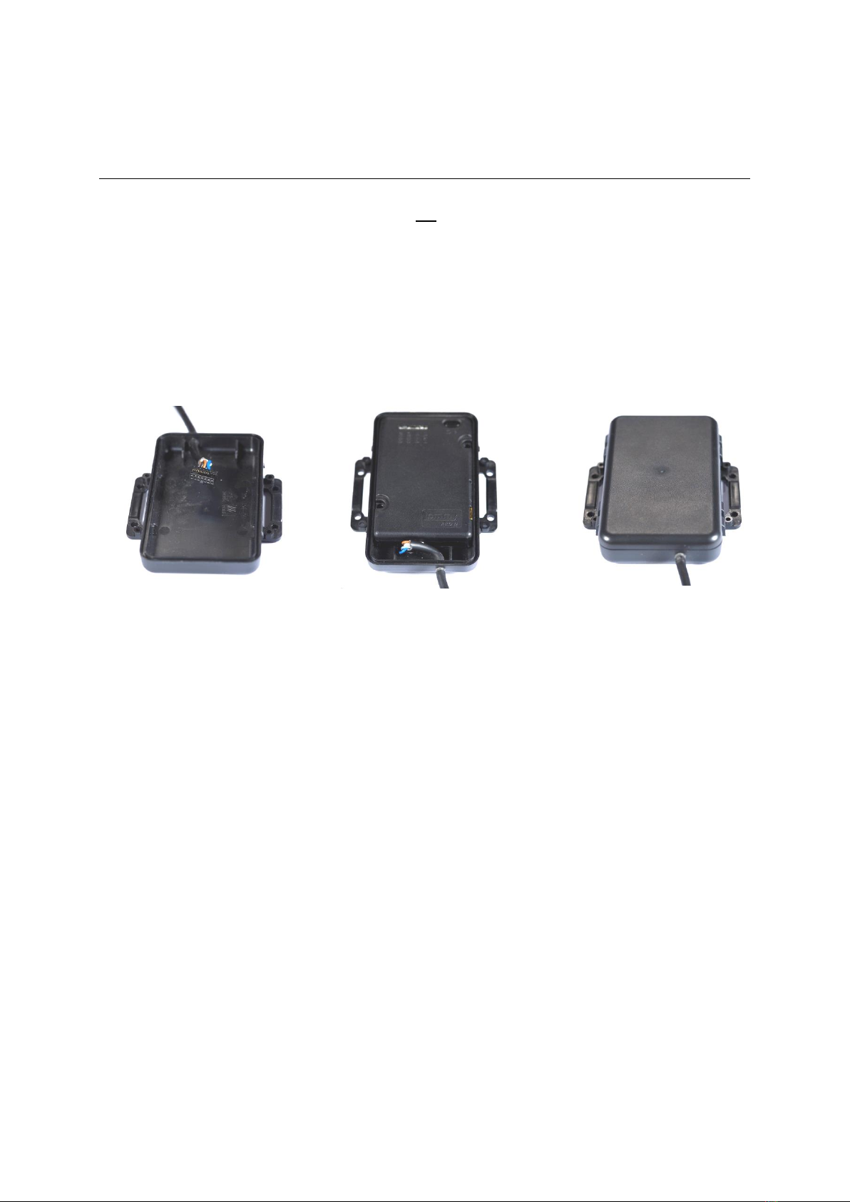
1Mounting the unit
The Asset Light and Asset Light Pro units can be mounted on various places on the vehicle, but to
ensure best possible GPS and GSM signals, it must not be placed under metal. Plastic, fibreglass and
fabric will not affect the signals. The antenna is located at the end opposite the connector. Use the
supplied splash-proof mounting box.
Protect from sunlight and do not expose to temperatures under -20oC and above +45oC Celsius.
Important: Mount the supplied 1A splash-resistant auto fuse on the white wire to permanent supply.
Place the fuse as close to the power source as possible to protect the vehicle.
To obtain a water-proof installation, mount the supplied four locking devices.
Mount the unit on a suitable place where it is protected from water. Never clean the unit with a high-
pressure cleaner.
The wire output must face downwards.
When attaching the power-/multi connector to the unit, you have to hear a click sound to ensure, that
the connector is attached properly. Possibly you have to press it gently further into the connector with
a tool, until you can hear the click.
Up to 5 minutes may pass from power on till the unit is charged and ready for use.
2
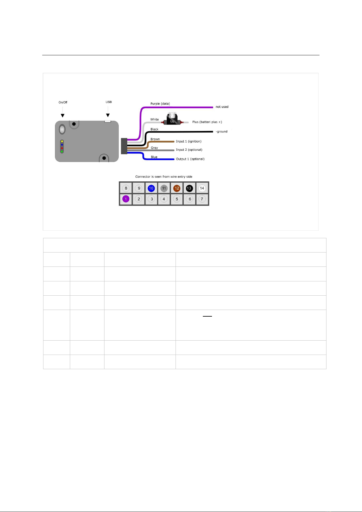
2Wiring for Asset Light
Asset Light is supplied with the following wires:
Wire chart
Pin
Colour
Function
Note
1
Purple
Not used
Dallas 1-wire –for temperature sensor
10
Blue
Not used
Digital Output
11
Grey
Not used
Digital Input
12
Brown
Terminal 15 ignition
Ignition (has to be connected –if there is no ignition
signal in the vehicle connect the cable to terminal 30
+24 Volt)
13
Black
Terminal 31 ground
Battery minus terminal
14
White
Terminal 30 +24 Volt
Constant supply between +10 Volt to +60 Volt

3
3Wiring for Asset PRO with one-wire temperature sensor
Asset Pro with temperature sensor(s) is supplied with the following wires:
Wire chart
Pin
Colour
Function
Note
1
Purple
Temperature
Dallas 1-wire –for temperature sensor
2
Orange
TX (RS 232)
Used for ThermoKing / Carrier
3
Green
RX (RS 232)
Used for ThermoKing / Carrier
4
Black/Whit
e
CAN
Not used
5
Red/White
CAN
Not used
10
Blue
Outout
Not used
11
Grey
Input 2
Not used
12
Brown
Terminal 15
ignition
Ignition (has to be connected –if there is no ignition signal in
the vehicle connect the cable to terminal 30 +24 Volt)
13
Black
Terminal 31
ground
Battery minus terminal
14
White
Terminal 30
+24 Volt
Constant supply between +10 Volt for +60 Volt
4
To test that the temperature sensors are detected and what temperatures are being measured, send a
SMS with the text OWTEMP-SHOW to the data number of the SIM-card mounted in the unit. The unit
will return a SMS with a list of the detected temperature sensors and the measured temperature. If the
returned value is “No sensors defined”, the sensor is not responding – check the installation! The
answer can be divided into several SMS if the content of the response contains too many characters.
The responds SMS can look as follows:
283326B30100007C = 27.3
2974E541564B1575 = 7.3
(Serial number) (measured temperature)
3.1 Cable for one-wire sensor
It is very important to use a twisted pair cable when an extension is needed. The cable should
preferably be the same type as the original sensor cable. The cable is with silicone outer jacket and
Teflon inner jackets so it is durable in high and low temperatures. The capacity between wires must
not be higher than 10 –15 pF per meter. Total length (added) for all sensors is maximum 20 meters.
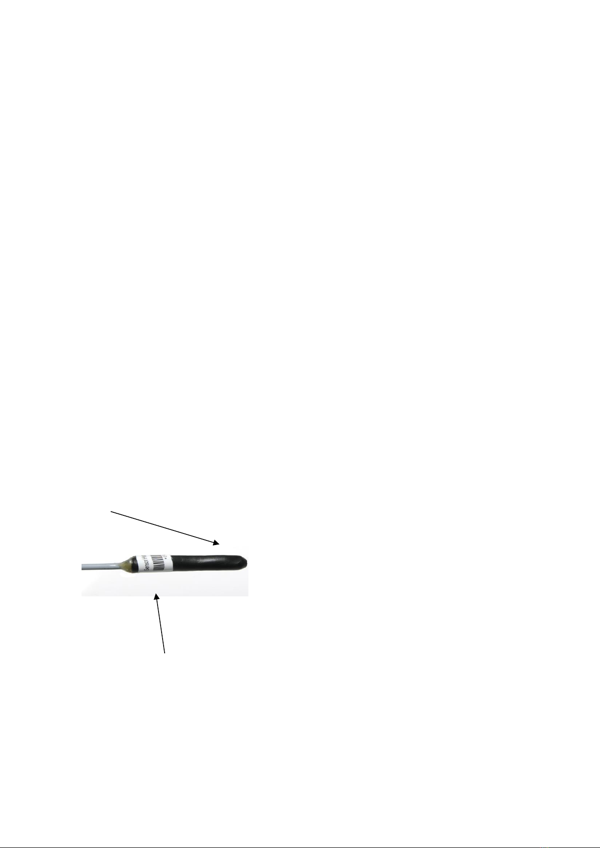
3.2 Temperature sensor –PRO version only
Where to mount the temperature sensor
Possible places to mount the temperature sensor:
•At the air intake of the cooling system
•At the air out of the cooling system
•On a central place in the compartment
AddSecure recommends that you agree on a mounting place with the customer.
Mounting/fixing the temperature sensor
Take care not to damage the temperature sensor when mounting/fixing it and make sure it is placed
well protected.
The sensor head must be free, i.e. it must not be covered by a bracket, glue, etc.
Sensor ID
Each sensor is labelled with a unique ID No. Enter this ID number and state the mounting place on the
data sheet.
The data sheet must be given to the AddSecure support.
More temperature sensors
5
Up to 8 external temperature sensors can be connected to an Asset Pro. If more temperature sensors
are connected they must be parallel mounted. White core to white core, and brown core to brown
core. Wires may be extended. All soldering must be isolated.
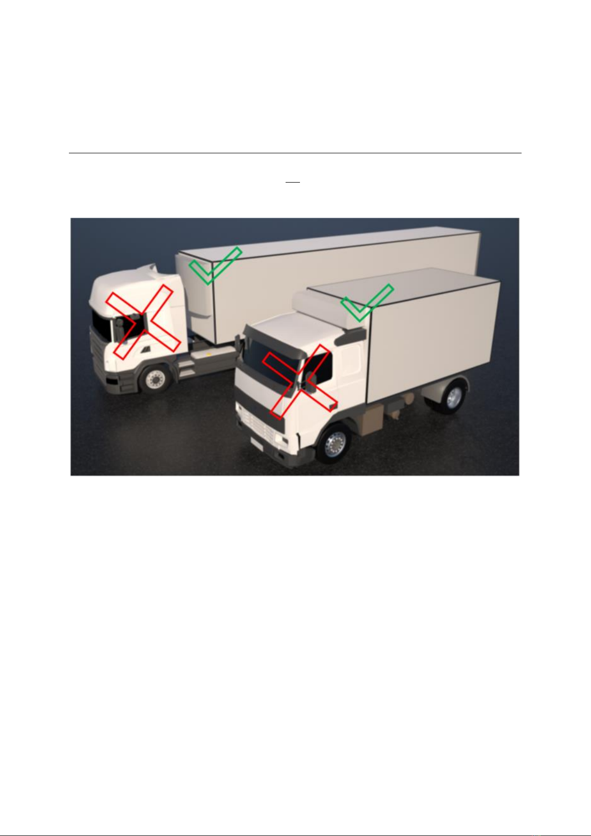
4Wireless Sensors
When mounting wireless sensors the Asset unit is not allowed to be placed in the trucks cabin.
The Asset unit should be mounted on the trailer or cargo unit.

6
4.1.1 Wireless temperature sensor
4.1.2 Wireless Door sensor
.
Awireless door sensor consists
of two parts, the Sensor (the
larger of the two) and a Magnet
(the smaller one).
It’s important that the sensor is
fitted to the door and that the
magnet is mounted to the
ceiling.
Depending on materials
between and around the sensor
and Asset unit, the range will
vary. e.g. the Asset unit cannot
be mounted in the trucks cabin
and communicate with the
sensor.
Note!
Write down the serial number of
the sensor located on the back
of the sensor.
Awireless temperature sensor consists of only one part,
the Sensor. Depending on materials between and
around the sensor and Asset unit, the range will vary.
e.g. the Asset unit cannot be mounted in the trucks
cabin and communicate with the sensor.
Note!
Write down the serial number of the sensor located on
the back of the sensor.
7
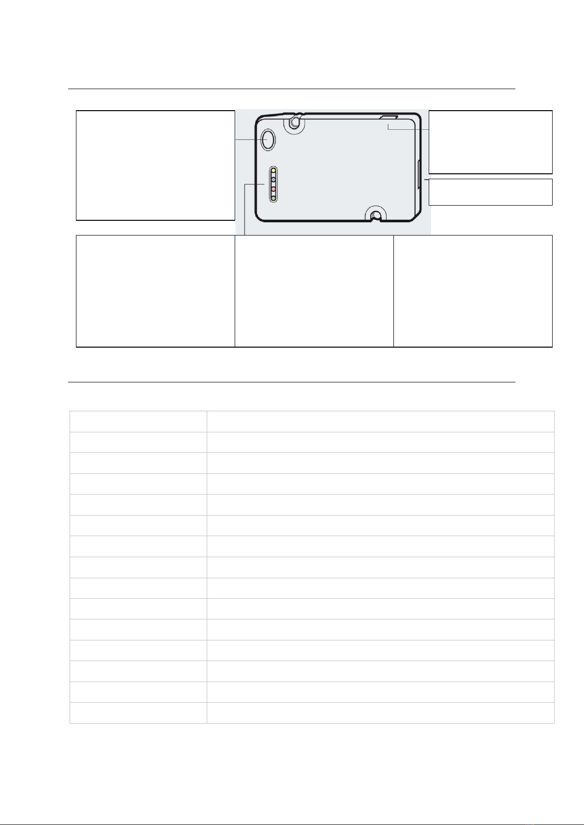
5Unit on/off and LED
6Final test
Send a SMS with the text: STAT to the GSM number of the unit. The following reply must be received
Reply
Meaning
Version=Blackbird 0.11
Software version
OPT2
Firmware Version in OPT2 board (PRO version only)
FW=0.35
Firmware program version
NodeID=3090818019
The serial number (S/N) of the unit
BattV=3987
Current battery voltage in mV –typically between 3650mV and 4200mV
Runtime= 3239
Number of seconds that the unit has been on
MCC=23802
Provider network code
Signal= 81
GSM signal strength –must be between 100 and 50. Low is best
Sat=11
No of satellites
HDOP=10
GPS HDOP value GPS quality
Ichg=127.6
Charging power
Bt=35.60
Battery temperature
Odo
Current Odometer value
Vt
0/1 valid time or not on unit
All values stated after = are examples.
ON/OFF button
When the unit is off it must not be
connected to a power source.
•Press button for 5 seconds till yellow lamp
starts to flash differently.
•Release the button and press it briefly
again. Turn off the unit.
Yellow. System service
•Constant light: System starts.
•1 flash: System is on, but not connected
to GSM data.
•2 fast flashes: System is on server.
Blue. GPS receiver
•1 quick flash: No GPS satellites received
•1 long flash followed by a number of quick
flashes: Receiving GPS. The number of
short flashes states the number of
satellites being received.
Red. Power/Charging status Constant light:
Fully uploaded
•1 flash: battery low level
•2 flashes: Charging
Green. GSM service
•Flashing sporadic: OK
•Flashing constant: SIM card error
USB-input for charger
230 V charger and
12/24 V cigarette charger
available as option.
Installation inputs
Yellow
Blue
Red
Green

8
7Carrier Transicold
7.1 Datalogger, Datacold 500, 600 and EuroScan X2
7.1.1 Mounting
The Asset Pro can be mounted on the rear of the datalogger
7.1.2 Connection
It mush flush with the edges
Make sure that there is room for the
printer cable

9
7.1.3 Ignition Connection
The ignition input (Brown –pin 12) can be connected to the trailer 24 volt (Light). It will then show if
the trailer is connected to a truck with ignition on (Light turned on). Trailer and datalogger has
separated ground. Remember to mount the 1 kohm resistor R2. On trucks the ground is normally
common and the resistor is not needed.
Can also be connected to the ignition of the refrigeration unit and used to indicate is the cooler is
running.
If this option is not used, the brown wire must be connected to the white wire (Datacold 12 volt).
7.1.4 Configuration of datacold 500, 600 and EuroScanX2
The configuration of the datacold must be done before the Lommy works.
•Hold the green button for 2 seconds.
•The display shows "Enter PIN“
•Factory code is 1111 (press 4 times the blue)
•Select menu 11 with the arrow keys
•Datacold 500 - Com 1 should be “Thirdparty”
•Datacold 600 –Com 1 should be “Partner Protocol”
•EuroScan –Com 1 should be “Old ES Protocol”
•Com 2 should be Vector, TM or R / T depending on the unit which is mounted.
7.1.5 System configuration
Note the placement and names of the different temperature sensors and set-points. Needed for system
configuration.

10
8ThermoKing
8.1 Datalogger DAS / SR2 / CargoWatch
8.1.1 Serial RS 232 connection to CargoWatch.
Solder the TX and RX connections on the connector on the controller board or use a connector.
The 1 kohm resistor R1 secures that the CargoWatch Port is not blocked when connection in parallel
with the connector. When a connector is used R1 is not necessary.
8.1.2 Ignition Connection
The ignition input (Brown –pin 12) can be connected to the trailer 24 volt (Light). It will then show if
the trailer is connected to a truck with ignition on (Light turned on). Trailer and datalogger has
separated ground. Remember to mount the 1 kohm resistor R2. On trucks the ground is normally
common and the resistor is not needed.
Can also be connected to the ignition of the refrigeration unit and used to indicate is the cooler is
running.
If this option is not used, the brown wire must be connected to the white wire (CargoWatch 12 volt).
8.1.3 Configuration of datalogger
(Will be described later)
8.1.4 System configuration
Note the placement and names of the different temperature sensors and set-points. Needed for system
configuration.

11
8.2 i-Box

12
9Hultstein
9.1 HUK Datalogger
To connect to a HUK, you will need a
male
DB9 connector.
Power is connected as usual.
PINOUT
Asset
DB9
Green
2
Orange
3
Black
5
Jumper between 7 & 8
10 System configuration
See the document: Asset configuration AddSecure.
This manual suits for next models
2
Table of contents
Popular Automobile Accessories manuals by other brands

Thule
Thule Rapid System 1362 Fitting instructions

Bestop
Bestop HighRock 4x4 Element 51814 installation instructions

Sony
Sony DCC-E34CP - Car Battery Cord operating instructions

Loughbless
Loughbless BC28 user manual

Airxcel
Airxcel Aqua-Hot GEN1 Series installation manual

LSD-Doors
LSD-Doors 50075004 installation instructions


