OVERVIEW
Safety Instructions
This manual, provided by the manufacturer, is part of the
air conditioner, which must be read by users carefully. The
information provided in the instructions, if correctly observed,
can ensure the correct use of the machine and help users
eliminate or reduce the risk of accidents and injuries.
Safety Symbol
This is a safety warning sign. When you see this sign in this
manual, the corresponding contents may cause personal
injury, so you must follow the recommended preventive
measures and safe operation instructions.
Sign:
WARNING or CAUTION signs are used simultaneously,
which indicate the potential risk level.
WARNING
Indicate a potentially dangerous situation that may lead to
death or serious injury.
NOTE
Indicate a potentially dangerous situation, which may lead
to minor or moderate injury.
CAUTION
Indicate a potentially dangerous situation, which may
cause property damage.
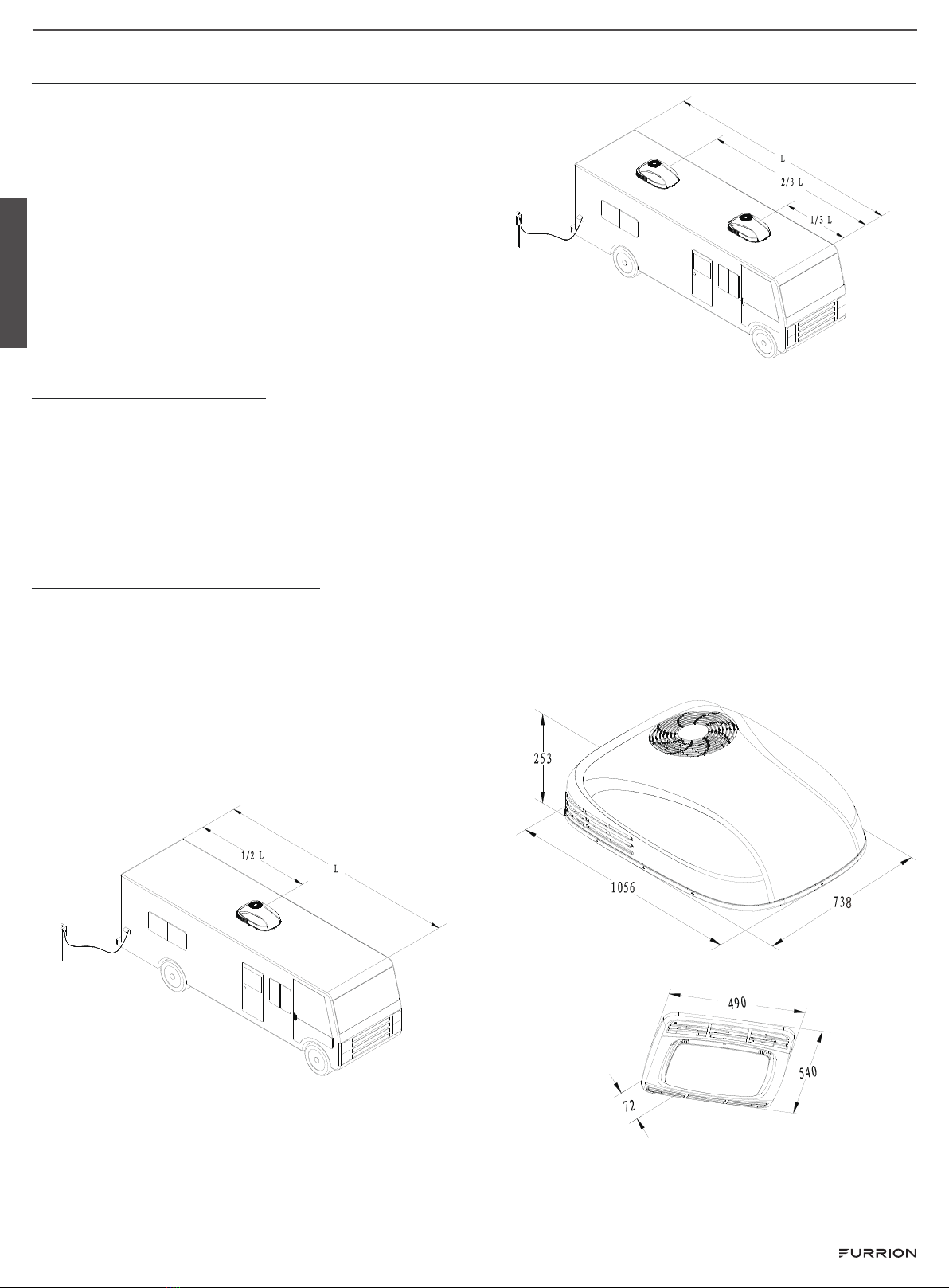
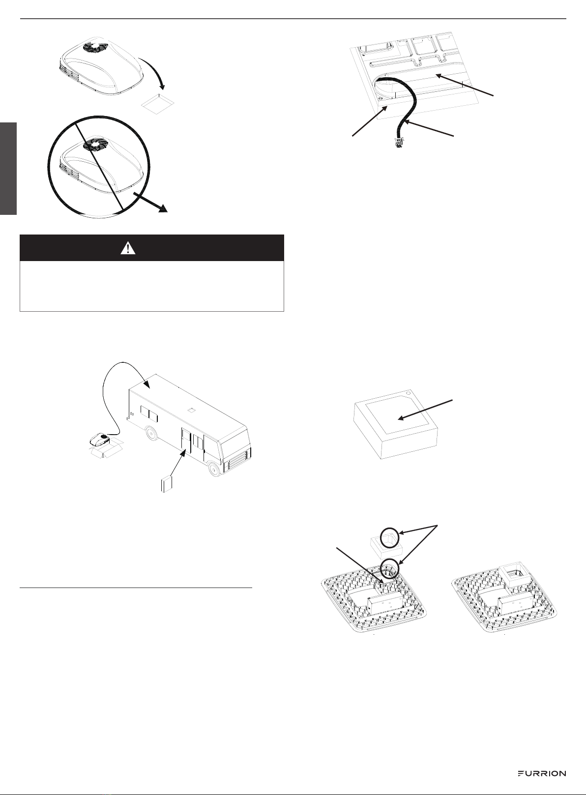
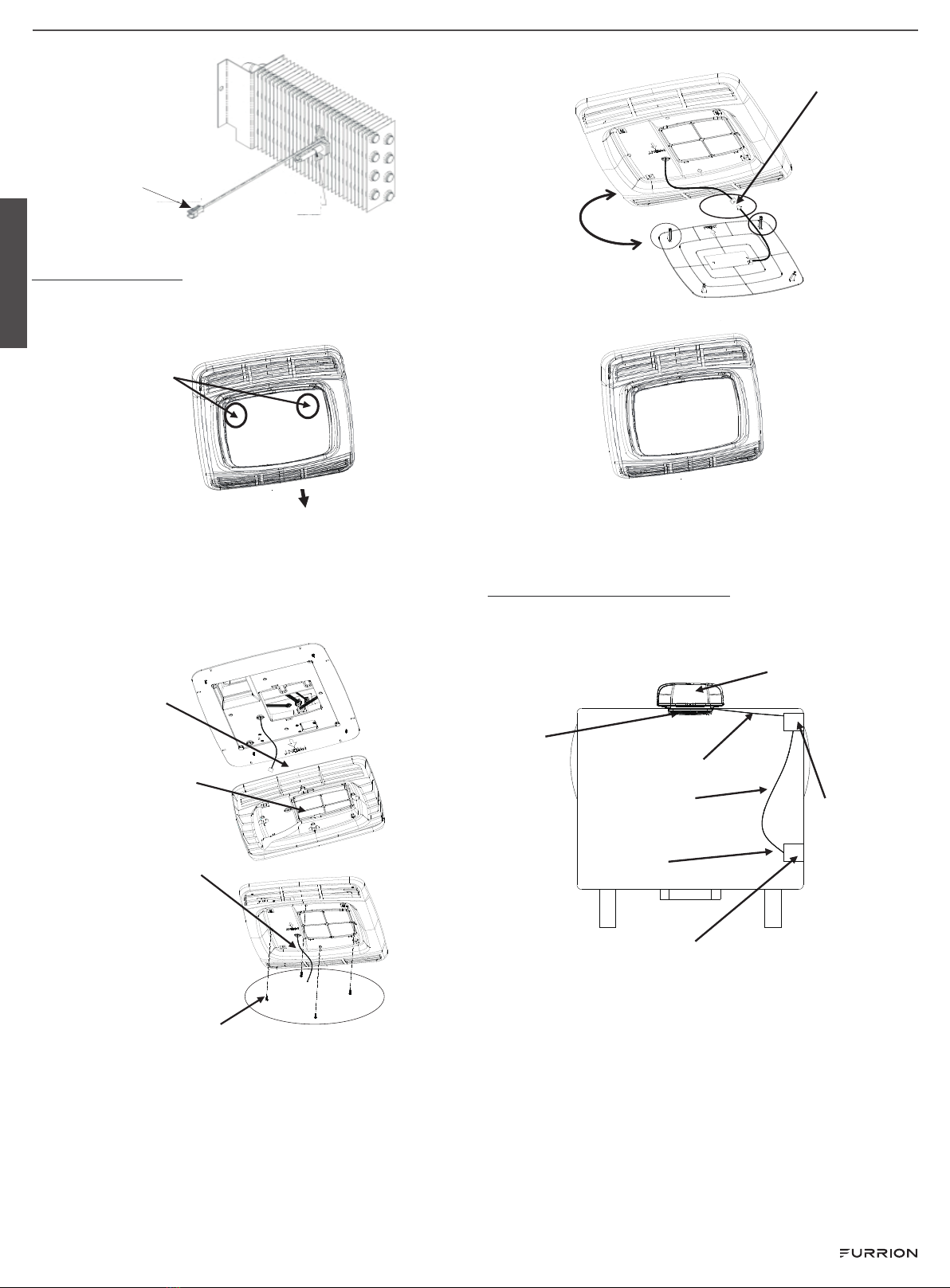
Installation Environment of Air
Conditioner
●It can be installed during the production or after the
completion of RV.
●The air conditioner can only be installed horizontally on
the top of the RV.
●The minimum spacing between rafters and joists on the
roof structure is 15¾" (400mm).
●The minimum thickness of the roof of RV is 1" (26mm) and
the maximum thickness is 3⅞" (100mm).
●When the roof thickness is greater than 3⅞" (100mm),
additional air duct is required for connection.
Introduction of Air Conditioner
The design and installation of this machine is suitable for RV
to improve its internal temperature and provide a comfortable
environment. It can cool the RV when it’s hot and warm up the
RV when it’s cold. Its temperature can be adjusted in the two
environments.
User Guide
The performance of air conditioner is related to the heating
condition of insulation box of RV itself. Users can take some
preventive measures to reduce heat entry, so as to improve
the refrigeration performance of air conditioning equipment.
When outdoor temperature is high, the following methods
can be adopted to reduce the heat entry of RV and improve
work efficiency:
●Park the RV in a cool place.
●Strengthen thermal insulation of the compartment,
remove or block the opening in the vehicle, and block
the window with shade curtains (shutters or hanging
curtains).
●Close doors and windows or avoid frequent opening and
closing of them.
●Avoid using heating devices inside the vehicle. Turn on
the air conditioner in advance to achieve better effect.
When the indoor or outdoor temperature is high, setting
the air conditioner in cooling mode and turning on high
wind speed will bring the performance of air conditioner
into full play.
NOTE: During the use of this product, due to the great
change of air temperature in the vehicle, when the
temperature drops rapidly, part of condensate will adhere to
the surface of objects near the air outlet, which is a normal
phenomenon. After the air conditioner works normally for
a certain period, it will be automatically dried and detached
from the surface of objects. Therefore, when the air
conditioner works, please close the doors and windows as
much as possible to reduce the coagulation of water vapor
on the surface of objects inside the vehicle.
The manufacturer will not be responsible for any
damage arising from condensation on the ceiling or the
surface of other objects caused by the condensate of
this product.
Main Parameters
FACR09SM-PS FACR12SM-PS
Rated cooling capacity 9000BTU 12000BTU
Rated heating capacity 9500BTU 12500BTU
Power supply 220-240 VAC/ 50Hz
Compressor
Running current - 4.2A Running current - 5.5A
Locked -rotor current
- 22.5A
Locked -rotor current
- 28A
Rated cooling power 1000W 1300W
Rated heating power 800W 1060W
Air volume (high
speed)
490m/h 480m/h
Refrigerant (R 410 A) 620g 740g
Cable standard 12AWG Copper wire with the length of no more
than 8m
Circuit protection 20A safety wire or fuse
NOTE:
●Please use the connecting wires complying with the
national regulations.
●During model selection of the generator, the total power
consumption of RV must be considered.
Tip: the generator will lose power due to high altitude and
lack of maintenance.
●Circuit protection: please use leakage circuit breaker all
the time.
English
Rev: 06-30-22
- 2 - CCD-0005745