Inventure Automotive G2 User manual

FMS Gateway G2™
interface

User’s Manual
Inventure
FMS Gateway G2™interface

User’s Manual FMS Gateway G2™ interface
© Inventure Automotive Electronics R&D, Plc.
Legal Notice
Information furnished in this publication is believed to be accurate and reliable. However,
Inventure assumes no responsibility for the consequences of use. Information contained in this
publication regarding the device applications and the like is intended through suggestion only.
Product specifications are subject to change or modification without notice.
This document is for use by the intended recipient and contains confidential information under
applicable law. You are hereby formally notified that any use, copying or distribution of the
document, in whole or in part, is strictly prohibited.
This publication supersedes and replaces all information previously supplied.
Trademarks
The Inventure logo and product names are trademarks of Inventure, Inc. and are protected by
copyright law.
All rights reserved.
Copyright Notice
© Copyright 2020, Inventure, Inc.
Revision
D01-018-09-04-00-30EN
Contact
INVENTURE Automotive Electronics R&D, Plc.
11 Tarcali Street
H-1113 Budapest
HUNGARY
Phone: +36 1 381-0970
E-mail: support@inventure-automotive.com
URL: www.inventure-automotive.com

User’s Manual FMS Gateway G2™ interface
© Inventure Automotive Electronics R&D, Plc.
Table of contents
1INTRODUCTION .............................................................................................................5
2THE FMS GATEWAY G2™ INTERFACE........................................................................5
2.1 MAIN FEATURES........................................................................................................5
2.2 FEATURES IN COMPARISON TO FMS GATEWAY G1™..................................................5
2.3 ADDITIONAL FEATURES..............................................................................................6
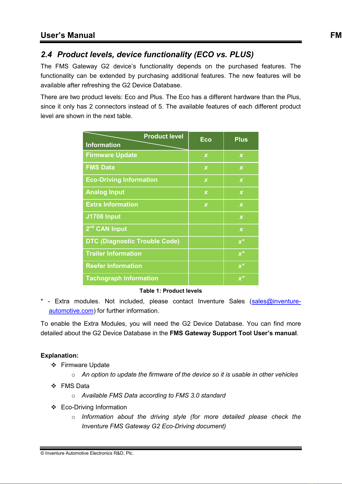
2.4 PRODUCT LEVELS,DEVICE FUNCTIONALITY (ECO VS.PLUS) ......................................7
2.5 HOW TO USE INVENTURE FMS GATEWAY G2™..........................................................9
3SAFETY NOTICES........................................................................................................10
4PACKAGE CONTENTS ................................................................................................11
5CONNECTION OVERVIEW...........................................................................................12
5.1 V_CAN 1CONNECTOR............................................................................................12
5.2 MAIN CONNECTOR .................................................................................................13
5.3 V_CAN 2CONNECTOR............................................................................................13
5.4 TACHO CONNECTOR (OPTIONAL EXTRA FEATURE) ..................................................14
5.5 DIAG CONNECTOR .................................................................................................15
5.6 USB MINI CONNECTOR ...........................................................................................15
6INSTALLATION TO VEHICLE ......................................................................................16
7TROUBLESHOOTING, LED STATUS ..........................................................................17
7.1 PROPER OPERATION ...............................................................................................18
7.2 V_CAN 1ERROR ...................................................................................................18
7.3 V_CAN 1IDLE........................................................................................................18
7.4 DIAG IDLE .............................................................................................................19
7.5 UNKNOWN VEHICLE.................................................................................................19
7.6 V_CAN 2ERROR ...................................................................................................19
7.7 V_CAN 2IDLE........................................................................................................19
7.8 K-LINE IDLE............................................................................................................20
7.9 FMS CAN OUTPUT ERROR .....................................................................................20
7.10 BOOTLOADER STATE (USB CONNECTED) .................................................................20
8INVENTURE SUPPORT INFORMATION ......................................................................21
9SYSTEM CHARACTERISTICS .....................................................................................22
10 WARRANTY..................................................................................................................23
11 HOW TO CONTACT INVENTURE? ..............................................................................24
12 LIST OF FIGURES ........................................................................................................25
13 LIST OF TABLES..........................................................................................................26
14 NOTES ..........................................................................................................................27

User’s Manual FMS Gateway G2™ interface
© Inventure Automotive Electronics R&D, Plc.
1 Introduction
Thank you for purchasing an Inventure product. Your new FMS Gateway G2™interface is a
carefully engineered, high quality durable product with intelligent features and robust styling.
It is designed to give you the quality and convenience you expect from an automotive
measuring instrument.
To familiarize yourself with all the features of your unit please read the following instructions
carefully. Retain this guide for future reference.
2 The FMS Gateway G2™ interface
The interface connects to vehicle electronic communication channels, acquires and transfers
real vehicle sensor data on its output. The output format can be standard FMS CAN, and/or
RS232. The output data can be transferred via hardwire (FMS Gateway output cable –FMS
CAN and/or RS232) method.
The FMS Gateway G2™ has only one firmware for each manufacturing group and it
uses Automatic Vehicle Detection which means that after installing the device will detect
your vehicle by itself.
2.1 Main features
This intelligent interface provides solution for different needs, as listed below:
1 firmware for each manufacturing group
Automatic vehicle detection
FMS functionality (according to FMS 2.0 / 3.0 standard) to monitor vehicle
parameters
Eco-Driving functionality to monitor driver behavior
Additional CAN input for flexible CAN data capture
Analog input to monitor analogue signal
Tachograph functionality1to manage vehicle availability
Trailer information2to monitor vehicle gross weight, ABS activity, lamp status, etc.
Diagnostic Trouble Code3to assist vehicle maintenance
2.2 Features in comparison to FMS Gateway G1™
In comparison to FMS Gateway G1™interface the new generational device provides
additional features to the user, such as:
1 firmware for each manufacturing group
Automatic vehicle detection
1Extra feature: please contact Inventure Automotive for details
2Extra feature: please contact Inventure Automotive for details
3Extra feature: please contact Inventure Automotive for details

User’s Manual FMS Gateway G2™ interface
© Inventure Automotive Electronics R&D, Plc.
Additional vehicle parameters (according to FMS 2.0 / 3.0 standard)
Eco-Driving functionality to monitor driver behavior
Additional CAN input for flexible CAN data capture
Analog input to monitor analogue signal
Tachograph functionality1to manage vehicle availability
Trailer information2to monitor vehicle gross weight, ABS activity, lamp status, etc.
Diagnostic Trouble Code or MIL status3to assist vehicle maintenance
2.3 Additional features
The FMS Gateway G2 interface has advantageous features that are accessible via mini USB
connector, such as:
Flexibility: vehicle related firmware can be uploaded or updated
Configurability: interface output parameters can be set or filtered
Vehicle measurement: If the vehicle is not supported, then you can easy make a CAN
measurement using FMS Gateway G2. You just send this measurement to Inventure
Support (support@inventure-automotive.com), we analyze the files and update new
firmware as soon as possible
Troubleshooting: should you need further assistance during installation,
measurements can be recorded from the Support Tool PC software. The
measurement can be analyzed by Inventure experts and effective support can be
provided.

User’s Manual FMS Gateway G2™ interface
© Inventure Automotive Electronics R&D, Plc.
2.4 Product levels, device functionality (ECO vs. PLUS)
The FMS Gateway G2 device’s functionality depends on the purchased features. The
functionality can be extended by purchasing additional features. The new features will be
available after refreshing the G2 Device Database.
There are two product levels: Eco and Plus. The Eco has a different hardware than the Plus,
since it only has 2 connectors instead of 5. The available features of each different product
level are shown in the next table.
Product level
Information
Eco
Plus
Firmware Update
x
x
FMS Data
x
x
Eco-Driving Information
x
x
Analog Input
x
x
Extra Information
x
x
J1708 Input
x
2nd CAN Input
x
DTC (Diagnostic Trouble Code)
x*
Trailer Information
x*
Reefer Information
x*
Tachograph Information
x*
Table 1: Product levels
* - Extra modules. Not included, please contact Inventure Sales (sales@inventure-
automotive.com) for further information.
To enable the Extra Modules, you will need the G2 Device Database. You can find more
detailed about the G2 Device Database in the FMS Gateway Support Tool User’s manual.
Explanation:
Firmware Update
oAn option to update the firmware of the device so it is usable in other vehicles
FMS Data
oAvailable FMS Data according to FMS 3.0 standard
Eco-Driving Information
oInformation about the driving style (for more detailed please check the
Inventure FMS Gateway G2 Eco-Driving document)

User’s Manual FMS Gateway G2™ interface
© Inventure Automotive Electronics R&D, Plc.
Analog Input
oAn option to connect analog voltage sensor (e.g. fuel level sensor)
Extra Information
oUseful information that are not part of the FMS Standard, like information
about the doors, lights and seatbelt.
oOnly available if the sensor is present in the vehicle
J1708 Input
oProvides an input connection possibility for J1708 buses.
2nd CAN Input
oA second CAN input where other can bus or one of the extra modules can be
connected.
DTC (Diagnostic Trouble Code)
oProvides the decimal or hexadecimal error codes that are currently active or in
some vehicles MIL status information
oExtra module, please contact sales@inventure-automotive.com for further
details
Trailer Information
oCan provide information about the attached trailer such as ABS Status,
Retarder status, Trailer speed, Acceleration, Trailer distance, Trailer ID, Stop
lamp, Tyre pressure, Braking information (pressure, temperature, etc.), Axle
load, etc.
oSome information are only available if a sensor is present in the vehicle
oExtra module, please contact sales@inventure-automotive.com for further
details
Reefer Information
oProvides multi zone temperature monitoring and other information such as
operating mode, engine mode and total hours of operation.
oExtra module, please contact sales@inventure-automotive.com for further
details
Tachograph Information
oProvides driving information such as driving time, driver ID, cumulated driving
time, etc.
oExtra module, please contact sales@inventure-automotive.com for further
details

User’s Manual FMS Gateway G2™ interface
© Inventure Automotive Electronics R&D, Plc.
2.5 How to use Inventure FMS Gateway G2™
Identify your vehicle
oTo properly set up your device you will need to know your vehicle’s
manufacturer, type and in some cases the year it was manufactured. Check
your vehicle in the Inventure Supported Vehicle list. (support@inventure-
automotive.com)
E.g.: INV_FMSGW_G2_Supported_Veh_List_v04_20180618.pdf
Firmware update process
oInstall FMS Gateway Support Tool
See further details in the FMS Gateway Support Tool User’s manual
Check Fuel Tank size
oOn some vehicles the fuel tank capacity needs to be set manually. Because of
this, this information is present on every G2 related installation guide’s first
page with bold red font.
If you need to change the value, the exact value is written in the
manual
If you don’t need to change it, it is also stated in the document
oThe FMS Gateway G2™ uses automatic vehicle detection, it recognizes your
vehicle after connection. The firmware file has .i2b extension (E.g.:
G2_02_02_01_20__TRUCK.i2b)
oIf you wish to use any Extra Features (see Section 2.4), you need to have a
G2 Device Database. Please contact Inventure Sales (sales@inventure-
automotive.com) for further information.
Vehicle installation process
oDuring installation please refer to the vehicle specific Installation guide. Please
contact Inventure Support (support@inventure-automotive.com) for the install
guide.
E.g.: FORD_FOCUS_Mk3_2011-2014_INSTALL_GUIDE_G2_Plus_v06.pdf
oAfter device installation, please connect input cables (Power, Ground, Vehicle
CAN input and other inputs when needed). See Section 5 for more details.
oPlease connect the FMS Gateway G2™ output cables to the input of your AVL
device.
After successful installation and power-up, the device testing can be started.
oThe FMS Gateway G2™ has an in-built Status LED that indicates its operating
status. If everything works as it should, the LED flashes green once in every 6
seconds. If not, please check Section 7 for further information.

User’s Manual FMS Gateway G2™ interface
© Inventure Automotive Electronics R&D, Plc.
oThe complete vehicle tracking system can be tested online, by visiting your
fleet tracking system’s website, where you are able to see the vehicle data
beside the GPS position.

User’s Manual FMS Gateway G2™ interface
© Inventure Automotive Electronics R&D, Plc.
3 Safety notices
Please read the following safety instructions carefully. Inventure Automotive
accepts no liability for damage that results from disregarding the safety
instructions.
Usage of the interface is permitted for industrial purposes only.
The interface must not be used in situations in which human lives depend upon
the operation of this equipment.
Product must be installed by professional and this fact should be recorded legally
The interface may be damaged by contact with water or any liquids. Use and
store the interface in an area protected from water
Do not expose the interface to direct sunlight or high temperature (see section 11
for reference) to ensure proper operation

User’s Manual FMS Gateway G2™ interface
© Inventure Automotive Electronics R&D, Plc.
4 Package Contents
Please make sure that the package contains the items listed below.
FMS Gateway G2™ interface
CL-CAN (contactless CAN) sensor and/or CL-J1708 sensor (optional)
Cable set (optional)
User’s Manual (this guide)
Installation guide on the specific vehicle model

User’s Manual FMS Gateway G2™ interface
© Inventure Automotive Electronics R&D, Plc.
5 Connection overview
INPUT DESCRIPTION
CONNECTOR
Vehicle CAN 1 channel
V_CAN 1
Vehicle CAN 2 channel
V_CAN 2
Diagnostics channel
DIAG
Tachograph connection
TACHO
Main harness (Power, FMS CAN, RS232, Analog)
MAIN
Programming / Configuring / Measuring channel
mini USB B
Table 2: Input description
Figure 1: Device connectors
For the device proper functioning, please make sure to connect only to the following points
according to the charts. The rest should be left as is (DNC - Do Not Connect).
5.1 V_CAN 1 connector
4 3
12
V CAN_H 1
CL_PWR
V CAN_L 1
GND
Figure 2: Micro Fit 4-pin (V_CAN 1) assignment
Pin Nr.
Designation
Description
1
GND
Ground
2
V CAN_L 1
Vehicle CAN 1 bus CAN Low line
3
CL_PWR
Power output for CL-CAN sensor
4
V CAN_H 1
Vehicle CAN 1 bus CAN High line
Table 3: Micro Fit 4-pin (V_CAN 1) assignment

User’s Manual FMS Gateway G2™ interface
© Inventure Automotive Electronics R&D, Plc.
5.2 MAIN connector
89
10 67
12345
FMS TER1
FMS TER2
FMS CAN_L
RS232 RXD
FMS CAN_H
RS232 GND
RS232 TXD
ANALOG IN
IGN / BATT
Figure 3: Micro Fit 10-pin (MAIN) assignment
Pin Nr.
Designation
Description
1
GND
Ground
2
RS232 GND
RS232 Ground
3
RS232 RXD
RS232 channel receive data line
4
FMS CAN_L
FMS CAN bus CAN Low line
5
FMS TER 2
FMS CAN bus terminating resistor activation loop 2
6
IGN / BATT
Ignition / Battery + input
7
ANALOG IN
Analog sensor input (e.g.: fuel level sensor)
8
RS232 TXD
RS232 channel transmit data line
9
FMS CAN_H
FMS CAN bus CAN High line
10
FMS TER 1
FMS CAN bus terminating resistor activation loop 1
Table 4: Micro Fit 10-pin (MAIN) assignment
5.3 V_CAN 2 connector
4 3
12
V CAN_H 2
CL_PWR
V CAN_L 2
GND
Figure 4: Micro Fit 4-pin (V_CAN 2) assignment
Pin Nr.
Designation
Description
1
GND
Ground
2
V CAN_L 2
Vehicle CAN 2 bus CAN Low line
3
CL_PWR
Power output for CL-CAN sensor
4
V CAN_H 2
Vehicle CAN 2 bus CAN High line
Table 5: Micro Fit 4-pin (V_CAN 2) assignment

User’s Manual FMS Gateway G2™ interface
© Inventure Automotive Electronics R&D, Plc.
5.4 TACHO connector (Optional Extra feature)
TCOTER2
TCOCAN_L
456
23 1
DNC
TCO CAN_H
TCO D8
TCOTER1
Figure 5: Micro Fit 6-pin (TACHO) assignment
Pin Nr.
Designation
Description
1
DNC
Do Not Connect
2
TCO CAN_L
Tachograph CAN 2 bus CAN Low line
3
TCO TER2
Tachograph CAN bus terminating resistor activation loop 2
4
TCO D8
Tachograph D8 line
5
TCO CAN_H
Tachograph CAN 2 bus CAN High line
6
TCO TER1
Tachograph CAN bus terminating resistor activation loop 1
Table 6: Micro Fit 6-pin (TACHO) assignment
Tachograph connection:
1
2
3
4
5
6
7
2
3
4
5
6
8
1
2
3
4
5
6
7
8
1
2
3
4
5
6
7
8
1
DD C BA
Battery
4 1
52
6 3
TCO TER
TCO CAN_LTCO CAN_H
7
1
TCO D8
Inventure FMS Gateway
G2
TACHO Connector
DTCO
8
Figure 6: Tachograph connection
Notice!
Prior to installation please make sure that the Inventure FMS Gateway G2
firmware has enabled Tachograph functionality.

User’s Manual FMS Gateway G2™ interface
© Inventure Automotive Electronics R&D, Plc.
5.5 DIAG connector
4 3
12
DIAG A
GND
DIAG B
CL_PWR
Figure 7: Micro Fit 4-pin (DIAG) assignment
Pin Nr.
Designation
Description
1
GND
Ground
2
DIAG A
DAG bus A line
3
CL_PWR
Power output for CL-J1708 sensor
4
DIAG B
DAG bus B line
Table 7: Micro Fit 4-pin (DIAG) assignment
5.6 USB Mini connector
Please make sure to follow the below steps:
Connect FMS Gateway to computer (use Mini USB –USB cable)
Figure 8: USB Mini B to USB A cable
Install device driver
Install FMS Gateway Support Tool software
Activate FMS Gateway Support Tool software using license file (Send the activation
request file in e-mail to Inventure Automotive support)

User’s Manual FMS Gateway G2™ interface
© Inventure Automotive Electronics R&D, Plc.
6 Installation to vehicle
In order to avoid damaging the vehicle or the device the installation must be performed by
professional, skilled person.
During installation please consider safety instructions (see Section 3) and follow the
instructions below:
1. Make sure that the FMS Gateway G2™ device has the newest firmware and it is
appropriate for the vehicle model (check firmware version by using FMS Gateway
Support Tool)
2. Update the appropriate firmware to the device if necessary (by using FMS Gateway
Support Tool)
3. Update the settings if you need specific configuration (by using FMS Gateway Support
Tool)
4. Connect the vehicle communication bus wires to the interface input connectors by using
vehicle specific Installation guide
oConnect CL-CAN sensor to V_CAN 1
oConnect CL-J1708 sensor to DIAG if applicable
oConnect tachograph harness to TACHO if applicable
5. Tighten the device to avoid damaging the unit. You can use the 2 holes in the box to
secure the device with zip ties.
Figure 9 - Securing the device

User’s Manual FMS Gateway G2™ interface
© Inventure Automotive Electronics R&D, Plc.
6. Connect device output to the telematics device
oFMS CAN and/or
Default baudrate: 250 kb/s, according to FMS Standard
oRS232 and/or
Default baudrate: 115200 b/s
7. Turn vehicle ignition ON, start engine and check FMS Gateway device LED status. LED
should be flashing green once in every 6 seconds. Should it be different, please see
Troubleshooting on Section 9.)
8. Check telematics device’s operating status (LED indicator if available) then verify the
dataflow from vehicle on remote server database.
7 Troubleshooting, LED status
The FMS Gateway has a status LED on the face of the enclosure which indicates the current
operational mode.
When ignition turns ON the status LED lights RED for 5s (initialization process), after this the
status LED indicates the current operation state. The status LED flashes 1-5 times in 5s
period with different color, see attached table.
Status LED flashing states:
State
Status LED
Flashing / 5s
Proper operation
Green
1
No communication on device input
Not flashing
0
V_CAN 1 input Error
Red
2
V_CAN 1 input Idle
Red
3
DIAG input Idle
Red
4
Unknown Vehicle
Red
6
V_CAN 2 input Error
Red
7
V_CAN 2 input Idle
Red
8
K-Line input Idle
Red
9
FMS CAN output Error
Yellow
5
Bootloader state (USB Connected)
Yellow
rapid
Table 8: Device working status

User’s Manual FMS Gateway G2™ interface
© Inventure Automotive Electronics R&D, Plc.
LED STATUS: CAN Diag FMS
IDLE
OK
ERR
OK IDLE
ERR
OK OK
OK OK
OK
OK
IDLE IDLE
Firmware update
Figure 10: Status LED flashing
7.1 Proper operation
Device works correctly, LED flashes GREEN 1 time in 5s period.
In this working state the device gets power supply (voltage and current OK) and detects the
input CAN and/or DIAG communication channels’messages.
In this operating state the device and the GPS device connection are correct, the GPS
device sends CAN acknowledges (in case of FMS CAN connection).
7.2 V_CAN 1 Error
In case of the status LED flashes RED 2 times in 5s period the FMS gateway detects error
on V_CAN input channel. The device detects CAN errors on vehicle CAN communication
bus.
Possible Faults:
FMS Gateway Firmware does not fit for this vehicle model
oCheck the updated firmware version, use FMS Gateway Support Tool to read
firmware version. Update firmware if necessary.
V_CAN 1 bus connection wrong:
oCheck V_CAN 1 connections (CAN Low ~2,3V, CAN High 2,7V DC)
V_CAN 1 bus lines reverse connection:
oCheck V_CAN 1 connections reverse polarity (CAN Low ~2,3V, CAN High
2,7V DC)
7.3 V_CAN 1 Idle
In case of the status LED flashes RED 3 times in 5s period the FMS Gateway does NOT
detect any communication in V_CAN 1 input CAN bus, while detecting active communication
on DIAG bus
Possible Faults:
No communication on input channel:
oTurn Ignition ON and start the engine
V_CAN 1 bus connection is wrong:

User’s Manual FMS Gateway G2™ interface
© Inventure Automotive Electronics R&D, Plc.
oCheck V_CAN 1 connections (CAN Low ~2,3V, CAN High 2,7V DC)
V_CAN 1 bus lines have reverse connection:
oCheck V_CAN 1 connections for reverse polarity (CAN Low ~2,3V, CAN High
2,7V DC)
7.4 DIAG Idle
In case of the status LED flashing 4 times RED in 5s period the FMS gateway does NOT
detect any communication in DIAG input bus, while detecting active communication on
V_CAN1 bus
Possible Faults:
No communication on input channel:
oTurn Ignition ON, and start the engine
DIAG bus connection is wrong:
oCheck DIAG connections
DIAG bus lines have reverse connection:
oCheck DIAG connections for reverse polarity
7.5 Unknown vehicle
In case of the status LED flashes RED 6 times in 5s period the FMS Gateway has detected
an unknown vehicle. Please check the latest Inventure Supported Vehicle List or contact
support@inventure-automotive.com.
7.6 V_CAN 2 Error
In case of the status LED flashes RED 7 times in 5s period the FMS gateway detects error
on V_CAN 2 input channel. The device detects CAN errors on vehicle CAN communication
bus.
Possible Faults:
FMS Gateway Firmware does not fit for this vehicle model
oCheck the updated firmware version, use FMS Gateway Support Tool to read
firmware version. Update firmware if necessary.
V_CAN 2 bus connection wrong:
oCheck V_CAN 2 connections (CAN Low ~2,3V, CAN High 2,7V DC)
V_CAN 2 bus lines reverse connection:
oCheck V_CAN 2 connections reverse polarity (CAN Low ~2,3V, CAN High
2,7V DC)
Other manuals for G2
1
Table of contents
Other Inventure Automotive Automobile Accessories manuals
Popular Automobile Accessories manuals by other brands

Thule
Thule AeroBlade 7601 instructions

BPW
BPW AirSave Operating and installation instructions

Scosche
Scosche POWERUP 400 manual

Webasto
Webasto Thermo Pro 50 Eco installation instructions

Havis-Shields
Havis-Shields Side Slide-Out Step 1997-2007 Chevrolet Full Size Van... installation instructions

Mongoose
Mongoose MDVR-M Series Quick start up guide