Adel System MRF102 User manual

Via Luigi Barchi 9/B –Reggio Emilia 42124 –Italy
Tel. +39 0522 345518 –Fax +39 0522 345551 –www.adelsystem.com
Instruction Manual MRF102_7.docx
Page 1
MRF102
2- Channels Electronic Circuit Breaker
Instruction Manual
Thank you for having chosen one of our products for your work.
We are certain that it will give the utmost satisfaction and be a notable
help on your job and application.
1 Product Description
The MRF102 2-channel electronic circuit breaker with Din Rail and Wall
mounting is designed for current distribution and protection of 12V or
24V load circuits.
2 Safety and warning notes
WARNING –Explosion Hazard Do not disconnect
Equipment unless power has been switched off or the area
is known to be non-hazardous.
WARNING –Explosion Hazard. Substitution of components
may impair suitability for class I, Division 2.
WARNING –Switch off the system before connecting the module. Never
work on the machine when it is live. The device must be installed in
according to EN61010 or EN62368-1. The device must have a suitable
isolating facility outside the power supply unit, via which can be switched
to idle. Danger of fatal Injury!
WARNING –The device is equipped whit an internal fuse. If the internal
fuse blows Up (fails opens), it is most probable that there is a fault in the
device. If this failure occurs, the device must be returned to the factory.
3 How to Install
Mounting
Fig. 1 –Drawing of the MRF102
Din Rail or Panel Mounting
Fig. 1 shows a dimensional drawing of the MRF102. It is possible to
mount the device on Din rail or in panel and fix it by 4 screws 2.9x8-16.
There is no limit for the Panel thickness.
How to Supply MRF102
The MRF102 is supplied directly from the power source which provide
power to the load. The device it is protected by internal physic fuse, also
in worst case situations. The input rating is 8 –35Vdc.
Device Connection (Fig.2)
The following cable cross-sections may be used:
Solid
(mm2)
Stranded
(mm2)
AWG
Torque
(Nm)
Stripping Length
In:
0.2–2.5
0.2–2.5
24 –14
0.5–0.6
7 mm
Out:
0.2–2.5
0.2–2.5
24–14
0.5–0.6
7 mm
Signal:
AMP Modu II
Connection by the screw, type 2.5 mm2. Wiring terminal shall be
marked to indicate the proper connection for the power supply. Use
copper cables only, for supply connections, use wires suitable for at
least 75°C.
Fig. 2 –Connections to MRF102
Connection terminal and wiring
Reference
Description
1
+ Input Power
2
- Input Signal
3
Push Botton: ON / OFF Channel 1 and 2 / Config.Mode
4
LED Green, Orange, Red: Channel controls / Config.Mode
5
LED Green, Orange, Red: Channel controls / Config.Mode
6
Output 1
7
Output 2
8
Output Fail CN1 and CN2 or ADELBus connection
4 Drive a Channel
Turn On Channel
On the first power up, all channel are OFF.
To enabling channel 1(LED Blink Red for short time) push the set button
for short time: one time; < 1 sec.
To enabling channel 2(LED Blink Red for short time) push the set button
for short time: two time; < 1 sec.
Each channel could be enabled after a Switch off for Overload or Short
circuit, (LED Red ON). When the LED Red flash for 3 time, the devise it’s
ready to turn ON the channel. If the channel is ON, the device maintains
in memory the state also without the power; this function it is not enabled
if the device is in configuration mode.
Turn Off Channel
When the channel 1 is ON (LED Blink Green or Orange for short time)
push button for short time: one time and the channel turn OFF; < 1 sec.
When the channel 2 is ON (LED Blink Green or Orange for short time)
push button for short time: Two time and the channel turn OFF; < 1 sec.
If the channel is OFF, the device maintains in memory the state also
without the power.
5 LED indication
•Led RED ON: the channel is in protection due to Overtemperature,
Overcurrent, Over/Under voltage (<8.5V or >32.5V).
The device could be in this situation for some sec.
In this condition it is not possible turn ON the device.
•Led RED flashes three times for short time: the channel is OFF after
switch protection, but is ready to be turned ON.
Push the set button to turn ON the device.
•Led RED flashes one for short time, the channel is OFF but ready
for turn ON. Push the set button to turn ON the device.
•Led GREEN blinks for short time: the channel is ON and the current
through the channel is <80% of the tipping point switch.
•Led ORANGE blinks for short time: the channel is ON and the
current through the channel is >80% of the tipping point switch.
•Config. Mode: One Led OFF and the second Led ORANGE blinks,
in this condition it is enabled the procedure:
•Verify the trip current set for each channel
•Configure the trip current for each channel
7Out 1
6Out 2
1Input +
2Input -
4LED CN1
5LED CN2
3
ON / OFF out 1: Tich -
ON / OFF out 2: Tich –Tich -
PROG: Press 2 sec. -
8 Fail _ ADELBus
Via Luigi Barchi 9/B –Reggio Emilia 42124 –Italy
Tel. +39 0522 345518 –Fax +39 0522 345551 –www.adelsystem.com
Instruction Manual MRF102_7.docx
Page 2
6 Control and Programming
How to verify the trip current sett
Press the set button for more than 2 sec. until LED channel 1 start to blink
Orange.
•The number of Orange blink provide the number of Ampere set for
the trip current: 1 Blink = 1A … 10 Blink 10A
•Press the push button for more than 2 sec. until LED channel 2 start
to blink Orange.
•The number of Orange blink provide the number of Ampere set for
the trip current: 1 Blink = 1A … 10 Blink 10A
•End the procedure by holding down the button for 2 seconds until
the LEDs resume their regular flashing.
If the button is not pressed for 20 seconds, the procedure ends
automatically and the LEDs resume their regular flashing.
How to set the trip Current
Press the push button for more than 2 sec. until LED channel 1 start to
blink Orange.
•Option: it is possible count the number of orange blinks according to
the number of Ampere set for the trip current: 1 Blink = 1A … 10
Blinks = 10A
•Press the push button for a number of time equivalent to the desired
number of tripping Ampere.
•Verify option: successively press the desired Ampere, the device will
return the set number after 2 sec
•Correction option: correction of the current setting by pressing one
more time the set button: e.g., 6A + 1A more = 7A. When 10A is
reached, the counter restart from 1A.
•To confirm the New Trip Current setting, press the push button for 2
sec. until LED channel 2 start flashing orange.
Set the current limit for channel 2 in the same way as for channel 1.
•Confirm the new Trip Current of the channel 2 and finish the
Configuration procedure by holding the button for 2 seconds until the
LEDs start flashing regularly again.
•Mandatory: to ensure the new value is set, the procedure must be
completed. If the button is not pressed for 20 seconds, the procedure
automatically ends and the LEDs resume flashing regularly. The
device retains the old value.
Note: On the first power up the device is programmed at 3A for each
channel.
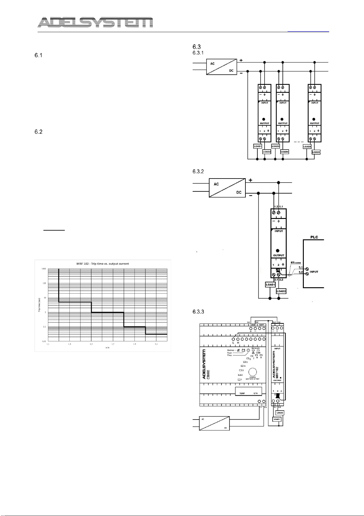
Connection Diagram
Multiple Devices
PLC Fail Connection
CBI60 –MRF102 Driver
Via Luigi Barchi 9/B –Reggio Emilia 42124 –Italy
Tel. +39 0522 345518 –Fax +39 0522 345551 –www.adelsystem.com
Instruction Manual MRF102_7.docx
Page 3
7 Technical data
Input Data
Supply voltage / at DC / Rated
value
12 –24 V
DC Input Voltage range (Vdc)
8 –35 V
Overvoltage overload capability
35 V
Input current / at rated input
voltage 12 - 24 V / Rated Value
20 A max (30A peak max 10
sec)
Maximum current consumption
10mA (12 VDC) - 10mA (24
VDC)
Required Back Up Fuse
Not required. Integrated
failsafe element (internal fuse)
Input Voltage Reset Output
7 …32 Vdc
Output Data
Voltage curve / at output
Controlled DC voltage
Drop Out
0.2 V
Number of outputs
2
Output current / up to 60 °C / per
output / rated value
10 A
Adjustable switch Off out current
1 …10A
Type of response value setting
via Blink code Led
Parallel switching of outputs
Yes
Bridging of equipment’s
No
Start Up
< 0.5 sec.
Surge voltage shutdown load
circuit
>32 Vdc
Max Capacitive Load
50.000 uF
Rated Surge Voltage
0.5 KV
Efficiency
Efficiency
97%
Power loss [W] (max)
1.5W (Nominal Operation)
Power dissipation
0.9 W (No Load operation)
Switching - off per output
Iout = 1.0 ...1.5 x set value
switch-off after approx. 5 s
Iout = 1.5 ...1.8 x set value
switch-off after approx. 1 s
Iout = 1.2 ...2 x set value
switch-off after approx. 0,1 s
Iout > 2 x set value
switch-off after approx. 0,03 s
Iout > set value and Vin < 15%
(24V); (12V)
switch-off after approx. 0,03 s
Turn On Output after Switch Off
-Manual Reset
-By Press Button
Waiting time after switch off Out
-5 sec max. (Hover load / Short
Circuit)
Protection and Monitoring
Internal Fuse protection type
16A per output (not replaceable)
Dielectric strength
Max 32 Vdc (on Load Circuit)
Display version
Three-color LED per output:
-green LED for "Output switched
through"
-Red LED for "Output switched off
manually"
-Red LED Blink for "Output
switched off due to overcurrent"
-Orange LED: Verify and Config
Connection for monitoring
device:
AUX1: connection 2 pin AMP
Configuration Aux1
1: as ADELBus for Driving,
Monitoring, Configuring
2: Out Alarm for For SwitchOff
Output
Diagnosis
-Common Signaling for
disconnection Last Output
-Single Channel: Current, set current
threshold, Status On/Off
- Reason of Output disconnection
Connection
Input 12 or 24V
1 Screw Type
0.2 - 2.5 mm2
(24 –12 AWG);
0.6 - 0.8 Nm
Input 0V
1 Screw Type
Outputs
1 Screw Type
Signal Output:
AUX1: connection 2 pin AMP
Ambient Conditions
Nominal Temperature
operation
-25 up to+60°C (>60°derating
2.5%°C)
Ambient Temperature
operation
-25 up to +70 °C
Ambient Temperature Storage
-40 up to +85 °C
Humidity at 25 °C, no
condensation
95 % to 25 °C (acc. to IEC 60721)
Vibration (operation) IEC
60068-2-6
<15 Hz, amplitude 2.5mm
<15Hz-150Hz, 2.3G 90 min.
Altitude: 0 to 2 000m - 6560
to 20 000ft
No restrictions
General Data
Protection Class (EN/IEC
60529)
IP20
Reliability: MTBF IEC 61709
> 700.000 h (Automatically Switch
Off Beck Light after 30 sec)
Protection class
III
Housing material
Polycarbonate
Foot latch material
Plastic POM
Screw type connection
0.2 - 2.5 mm2(24 –12 AWG
0.6 - 0.8 Nm
Dimension (w-h-d) mm
18 x 90 x 61
Weight
0.1 kg approx.
8 Norms
Immunity and Emission
The CE mark in conformity to EMC 2014/30/EU: Electromagnetic
Compatibility Directive; 2014/35/EU: Low Voltage Directive; ROHS
2011/65/EU: Restriction of the use of certain Hazardous Substances in
Electrical and Electronic Equipment (RoHS), as amended by
2015/863/EU
•EMC Immunity: EN61000-6-2
•EMC Emission: EN61000-6-3, EN 55022 ClassB
Electrical Safety for mounting
According to:
•Electrical Equipment for Machinery EN 60204
•Electrical safety (of information technology equipment)
IEC/EN EN62368-1.
•Safety requirements for electrical equipment for
measurement, control and Laboratory use IEC/EN 61010
9 Accessory
•RTConn: connector cable for the connection to AUX1. It is
possible drive the device through the ADELBus network.


