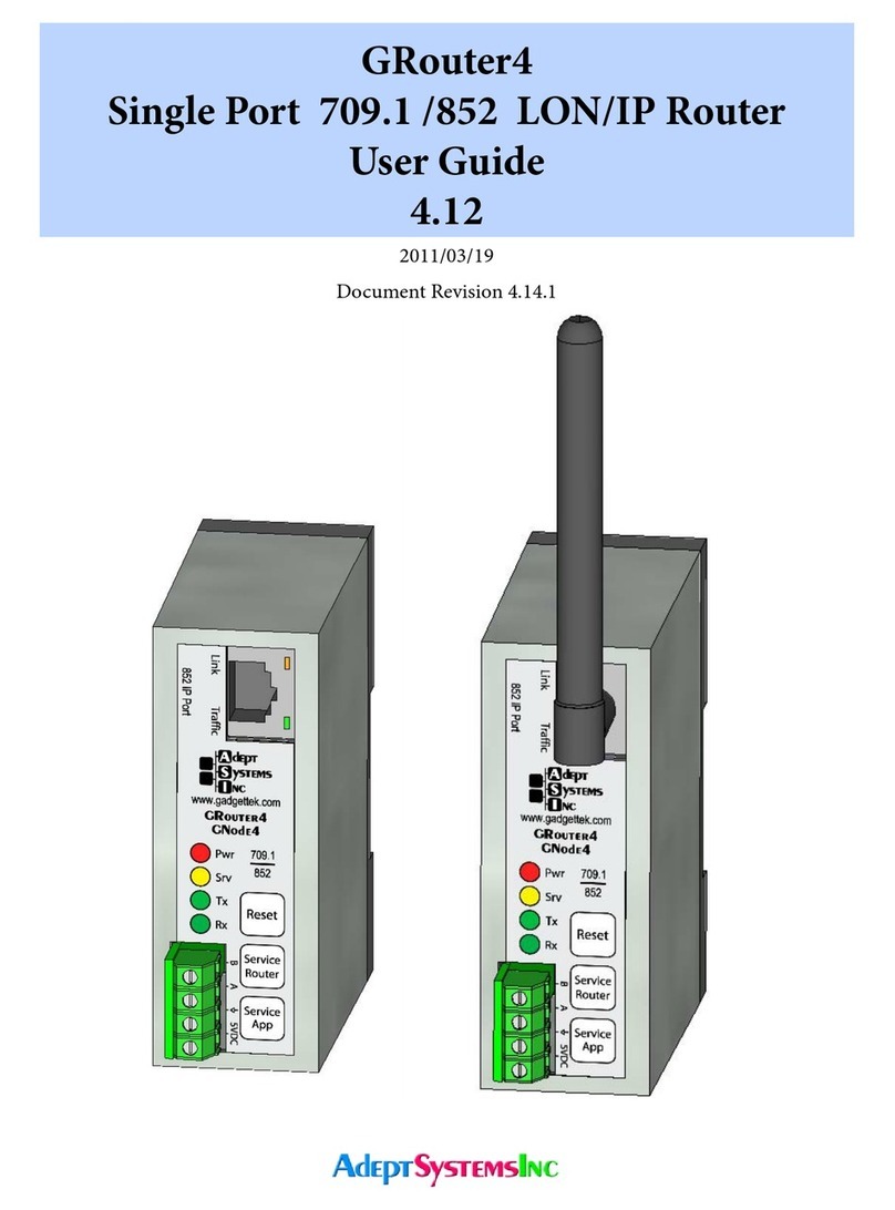
adept technology GRouter3 User manual

GRouter3
Single Port 709.1 /852 Router
User Guide
3.03
2007/02/10

Copyright © 2006 by Adept Systems, Inc. All Rights Reserved.
Printed in USA.
Version 3.0A, January 2006.
is document, the associated soware, and the associated online documentation are the
property of Adept Systems, Inc. and are loaned to the user under the terms of the End User
License Agreement. No title to or ownership of the soware described in this document or any of
its parts is transferred to customers. No part of this document may be reproduced or transmitted
in any form or by any means without the express written permission of Adept Systems, Inc.
Unauthorized copying or use of the soware or any associated materials is contrary to the
property rights of Adept Systems, Inc. and is a violation of state and federal law. is material
must be returned to Adept Systems upon demand.
Disclaimer:
Adept Systems makes no representations or warranties regarding the contents of this document.
Information in this document is subject to change without notice and does not represent a
commitment on the part of Adept Systems, Inc.
Trademarks:
GadgetStack and the Adept Systems Logo are registered trademarks of Adept Systems, Inc.
GRouter, GRouter3, GR3, GNode, GNode3, GN3, GRN3, GadgetNode, GadgetNIC, and
GadgetTek are trademarks of Adept Systems, Inc.
All other product and company names are trademarks or registered trademarks of their respective
holders.
Contact Information:
Adept Systems Incorporated
2966 Fort Hill Road
Eagle Mountain, Utah 84043 USA
Voice: 801.766.3527
Fax: 801.766.3528
Web: www.adeptsystemsinc.com
Email: info@adeptsystemsinc.com
-2-

Table of Contents
1. Overview ...................................................................................................7
1.1. Introduction ...........................................................................................7
1.2. Conguration Parameters .....................................................................9
1.3. Modes of Operation ............................................................................10
1.3.1. Manual Mode..................................................................................10
1.3.2. Normal Mode .................................................................................10
1.4. Applications of the GRouter3 router...................................................11
1.4.1. Multi-site building automation networks.....................................11
1.4.2. IP backbones for LON traffic aggregation ....................................11
1.4.3. Roaming Connections ...................................................................12
1.5. IP Addressing Modes ...........................................................................13
1.6. 852 to 852 Bridging Router Mode .......................................................15
1.7. Redundant Twin Mode ........................................................................15
1.7.1. Denitions ......................................................................................17
1.7.2. Status SNVT ...................................................................................18
1.7.3. Alarm SNVT...................................................................................19
1.7.4. Status Report UNVT......................................................................19
1.8. System Requirements...........................................................................20
1.8.1. System Requirements.....................................................................20
1.8.2. Button, Indicators, and Connectors for GRouter3 ......................21
1.8.3. Wiring .............................................................................................22
2. Web Conguration..................................................................................24
2.1. Default IP Conguration.....................................................................24
2.1.1. Ethernet ..........................................................................................24
2.1.2. WiFi (802.11b)................................................................................25
2.1.3. Establishing Connection................................................................26
2.1.4. Restoring Factory Defaults............................................................28
2.1.4.1. IP and WiFi settings.................................................................28
2.1.4.2. Web user name, password, and http port ...............................28
2.1.4.3. All parameters ..........................................................................28
2.2. Status Page ............................................................................................28
2.3. Router Setup .........................................................................................30
2.3.1. Normal Mode Router Setup...........................................................30
2.3.2. Manual Mode Router Setup...........................................................35
2.3.3. Bridging Router Setup ...................................................................35
-3-

2.4. IP Setup Page ........................................................................................37
2.5. WiFi Setup Page....................................................................................39
2.6. 709 Setup Page......................................................................................42
2.6.1. Node Parameters ............................................................................42
2.6.2. Forwarding Tables..........................................................................43
2.7. Channel List Page.................................................................................44
2.7.1. Normal Mode Channel List Page ..................................................44
2.7.2. Manual Mode Channel List Page ..................................................45
2.8. Device Detail Page................................................................................47
2.9. Diagnostics Page...................................................................................48
2.10. DDNS Setup Page.................................................................................50
2.11. Twin Setup Page ...................................................................................52
2.12. Twin Mode Status Page ........................................................................54
2.13. Contacts Page .......................................................................................56
3. Network Integration and Management...................................................58
3.1. Manual Mode Example ........................................................................58
3.2. Normal Mode With i.LON Conguration Server Example...............58
3.3. Communicating With Lonmaker With IP Interface..........................59
3.4. Commissioning GR3 Router With LonMaker ...................................60
3.5. NAT Router Example ...........................................................................62
3.6. DDNS Router Example ........................................................................63
3.7. Redundant Twin Mode Example.........................................................64
3.8. Conguring with the Coactive Router-LL..........................................68
3.8.1. Manual Mode..................................................................................68
3.8.2. Normal Mode With Router-LL Conguration Server .................69
4. Firmware Upgrade Instructions..............................................................70
-4-

List of Figures
Figure 1: Network Layers......................................................................................................8
Figure 2: Network Connector Types and Associated Layers..............................................8
Figure 3: CN to IP Router/Gateway Architecture...............................................................9
Figure 4: GRouter 3 Architecture.........................................................................................9
Figure 5: Multi-site building automation network with internet connectivity...............11
Figure 6: Example Hybrid Network ...................................................................................12
Figure 7: Example WiFi Ad Hoc Network.........................................................................12
Figure 8: Unicast .................................................................................................................13
Figure 9: Mulitcast ..............................................................................................................14
Figure 10: 852 Bridging Router Architecture....................................................................15
Figure 11: Two redundant routers between the same channels .......................................16
Figure 12: Redundant Twin Mode Application.................................................................17
Figure 13: Front 709.1 port connector detail ....................................................................22
Figure 14: Power port detail ...............................................................................................23
Figure 1: Ethernet setup with hub or switch .....................................................................24
Figure 2: Ethernet with direct connect crossover cable....................................................25
Figure 3: WiFi setup with access point ..............................................................................25
Figure 4: WiFi setup with ad hoc bridge............................................................................26
Figure 5: WiFi setup with ad hoc WiFi card on PC...........................................................26
Figure 6: WiFi setup with access point and WiFi card on PC ..........................................26
Figure 7: User Name and Password Authentication .........................................................27
Figure 8: Status Page ...........................................................................................................29
Figure 9: Router Setup Page ...............................................................................................31
Figure 10: Reboot Page .......................................................................................................34
Figure 11: Bridging Router Mode Setup Page...................................................................36
Figure 12: IP Setup Page.....................................................................................................38
Figure 13: 709 Setup Page Main Section............................................................................42
Figure 14: Subnet Forwarding Table..................................................................................44
Figure 15: Group Forwarding Table ..................................................................................44
Figure 16: Channel List Page..............................................................................................45
Figure 17: Channel List Page in Manual Mode .................................................................46
Figure 18: Device Detail Page.............................................................................................47
Figure 19: Diagnostics Page ...............................................................................................49
Figure 20: Dynamic DNS Conguration Page..................................................................51
Figure 21: Twin Mode Setup Page......................................................................................52
-5-

Figure 22: Twin Mode Status Page .....................................................................................55
Figure 23: Contacts Page ....................................................................................................57
Figure 1: Conguration Server Screen ..............................................................................59
Figure 2: Initial LonMaker Drawing..................................................................................61
Figure 3: Router Channel Setup.........................................................................................62
Figure 4: Service Pin Dialog ...............................................................................................62
Figure 5: Fully Commissioned Router...............................................................................62
Figure 6: NAT LAN to WAN Architecture ........................................................................63
Figure 7: LonMaker New Device Channel Dialog ............................................................66
Figure 8: LonMaker Drawing With Commissioned Monitoring Device ........................66
Figure 9: New Virtual Functional Device Dialog..............................................................67
Figure 10: Functional Blocks NV Shapes Dialog ..............................................................67
Figure 11: Functional Block On Drawing .........................................................................68
-6-

1. Overview
1.1. Introduction
eGRouter3 (GR3) router supports two open standard protocols, namely ANSI/EIA 709.1 and
ANSI/EIA 852. Both the ANSI/EIA 709.1 and ANSI/EIA 852 are dened by the Consumer
Electronics Association Technology & Standards R7.1 HCS1 Subcommittee. For more details see
http://ce.org/.For the sake of brevity the remainder of the document will refer to the
standards as 709.1 and 852. 709.1 is also known by its trademarked name, LonTalk®. A 709.1
network is also commonly referred to as aLocal Operating Network or LON. is document will
use 709.1 network and LON interchangeably.
e852 protocol acts as the transport service to convey 709.1 messages over Internet Protocol (IP)
networks. is technique of using another protocol (i.e. 852) to transport a message over an
alternate media is oen referred to as tunneling.In 852 parlance the tunneled protocol is a
Component Network (CN) protocol. e852 protocol is a generic tunneling protocol and is not
limited to 709.1. However, a particular implementation of the 852 protocol may only support the
tunneling of a single CN protocol. etunneled CN messages have no information or awareness
of the tunneling process. Although some of the gures in this document use CN or CN/IP to
represent a component network or component network to internet protocol connection, the only
CN currently supported by the GR3 router is 709.1
A component network protocol is oen called a eldbus due to its use for machine to machine
networking and control in the eld.is document, however, will only use the term component
network or CN.
852 not only provides the vehicle to transport ANSI 709.1 messages across IP, but it also provides
management of these connections or routes. A logical grouping of 852 devices that exchange
packets is called an 852 channel. One may think of an 852 channel as a kind of virtual LAN on an
IP network.
A GR3 router forwards 709.1 packets to or from an IP channel (using an Ethernet or WiFi
transceiver) and a CN channel (using twisted pair FT-10 or RS-485 transceivers). eGR3 router
has a presence on, or physical connection to, both channels. erouter takes 709.1 messages from
the component network, wraps them in an 852 packet and sends them over the IP network. e
GR3 router also receives 852 packets on its IP interface, unwraps them and puts the 709.1
messages on the CN channel. evirtual 852 channel looks like a CN channel to CN nodes. e
IP element is transparent. is enables a at network and is more easily managed and scaled than
using CN to IP interfaces that do not hide the IP element from the CN nodes. eimportant
thing is not what the CN to IP device is called but how transparent it makes the IP network
appear to the CN nodes.
Network connection devices can operate at different layers of particular networks protocol stack.
709.1 is an OSI 7 Layer type protocol. Whereas the Internet Protocol has only 4 layers. (See Figure
Figure 2.1 for a diagram of the different layers of the two protocols.)
-7-

Fig.1.1: Network Layers
A network connector is a device that joins different parts of a network. Connectors have a specic
name that is dependent on the layer at which the connector operates. For example a router
operates at the network layer and a gateway at the application layer. Because higher layers of the
protocol do not have access to some of the information stripped away by lower layers, network
connectors operating at different layers have different capabilities. ere is also some abuse of
terminology so that the descriptions of network connectors from different manufacturers may be
confusing. For example, a repeating router may be called a repeater for short. Although a
repeating router acts similarly to a physical layer repeater, it operates at the network layer and is
not equivalent. It is usually best to nd out at which layer a network connector operates.
Fig.1.2: Network Connector Types and Associated Layers
eGR3 router is amore complex connector because is connects two different protocols and also
connects the protocols at different layers. On the IP side the GR3 router operates at the
application layer and so is appropriately called an IP Gateway. On the 709.1 side the GR3 router
operates at the network layer and is appropriately called a 709.1 router. So depending on the user’s
perspective the GRouter3 (GR3) could be called a gateway or router or a router/gateway. (See
Figure 2.3)
-8-

Fig.1.3: CN to IP Router/Gateway Architecture
e GR3 router also employs a web server for conguration purposes. (See Figure 2.4)
Fig.1.4: GRouter 3 Architecture
1.2. Conguration Parameters
einformation required for successful ANSI/EIA 709.1 transport can be broken up into the
following two categories: device parameters and channel parameters.
Device parameters include information such as: IP address, IP port, Name, and Address of
conguration server.
A channel is a logical grouping of LON to IP routers. eminimum requirement for tunneling
ANSI/EIA 709.1 data is the use of two routers. Router A sends data to Router B and vise versa.
However, routers can also send data to more than one router. In such a case, Router A sends data
to Routers B, C, and D, which in turn send data back.
-9-

A channel, then, is dened as agroup of routers that all send information to each other. elines
of communication are open in both directions and to all members—a complete mesh of
connections.
Typically, channels are managed through the use of a conguration server (called Normal mode
see below). econguration server informs all members in the channel about the channel
information, which includes the adding and removing of channel members. Conguration
servers are capable of managing multiple channels, while routers belong to only one channel at a
time.
Lon to IP routers can also be managed manually by conguring each device uniquely (called
Manual mode, see below). In such a manual conguration, for proper operation, devices must
have mutual membership in each other’s channel lists. at is if Device A is in Device B’s channel
list then Device B must be in Device A’s channel list. However if Device C is in Device B’s channel
list, Device C does not have to be in Device A’s channel list.
1.3. Modes of Operation
e GR3 router can operate in one of two modes: (1) Manual, (2) Normal.
1.3.1. Manual Mode
In Manual mode the user has control over the GR3 router's conguration only. euser can
change the GR3 router's operating information and determine to whom the router will send
information. In Manual mode the GR3 router will honor read requests from other devices or
conguration servers, but it will block requests to write or change internal parameters. is is a
more secure mode and may be preferred on open networks. is mode is also preferable with
non-standard congurations such as Flood Mode or DDNS.
1.3.2. Normal Mode
Normal mode allows the user to view conguration data and channel data set by a remote
conguration server such as an i.LON® conguration server. econguration server sets some
of the operating parameters of the GR3 router. Conguration servers mostly manage the device's
channel. echannel is made up of other devices to which the GR3 router will tunnel or send
ANSI/EIA 709.1 data. In Normal mode the adding and deleting of devices is managed exclusively
by the assigned conguration server. econguration server provides a single interface to add
and delete devices. Finally, Normal mode permits read access to information by other devices and
write access to information for the assigned conguration server.
Note: Echelon’s LNS based VNI interface (LonMaker) only works in Normal mode. In order for a
GR3 router to communicate directly over an IP channel to a VNI interface requires that the GR3
router be in Normal mode.
1.4. Applications of the GRouter3 router
1.4.1. Multi-site building automation networks
einterfaces described here provide the management necessary for the ANSI/EIA 852 to tunnel
ANSI/EIA 709.1 packets successfully over IP. is ability provides wide area network (WAN)
-10-

support to ANSI/EIA 709.1 networks. is allows multi-building or multi-site connection of
automation networks.
Internet
Fig.1.5: Multi-site building automation network with internet connectivity
1.4.2. IP backbones for LON traffic aggregation
Furthermore, since the IP networks can support much higher traffic capacity, GR3 routers can
also be used to aggregate 709.1 trafficfrom several LON channels over one IP channel. eability
to aggregate larger traffic volumes allows several GR3 routers and other 709.1 to IP routers to be
used as network backbones for 709.1 networks.
Node Node
... Node Node
... Node Node
... Node Node
...
1.25Mbps LON 78 kbps LON 78 kbps LON 78 kbps LON
64 Nodes 64 Nodes 64 Nodes 64 Nodes
10/100 Mbps Ethernet ≈1000 - 100,000 pps
Network Management
ANSI 852 Interface
ANSI 852 709.1/IP
Gateway/Routers
Internet
852 /709.1/IP/WiFi
Router
Remote Monitoring
ANSI 852 Interface
802.11b Router
802.11b WiFi
Fig.1.6: Example Hybrid Network
-11-

Node Node
... Node Node
... Node Node
...
78 kbps LON 78 kbps LON 78 kbps LON
10/100 Mbps Ethernet
Network Management
ANSI 852 Interface
Internet
852 /709.1/IP/WiFi
Routers
Optional
WiFi to Ethernet Bridge
Ad Hoc 802.11b WiFi Channel
Fig.1.7: Example WiFi Ad Hoc Network
1.4.3. Roaming Connections
Finally, LON to IP gateways may be connected to specialized IP applications instead of to other
gateways. Connecting an IP application to a GR3 router provides these specialized applications
with roaming capabilities which would be difficult if these applications were required to be
directly connected to the 709.1 network (e.g., GadgetAnalyzer, LonMaker-3, etc.). An example of
how several GR3 routers can be interconnected to support an IP backbone for several LON
networks is show in Figure 2.5.
1.5. IP Addressing Modes
eGR3 router uses one of two forms of IP addressing: unicast and multicast. Multicast currently
only works when in manual mode.
eadvantage of multicast is that for networks with multiple Gateways (especially in ood
mode), multicast may be more efficient. edisadvantage of multicast is that some internet
routers do not support it. Multicast mode can reduce the IP trafficrelative to unicast when there
are alarge number of 852 devices in the channel. Up to 255 devices per IP domain are supported
with multicast. Some older IP routers do not support multicast and therefore you will not be able
to route 852 packets across a unicast only router with multicast addressing. IP router support for
Multicast is not a concern when all the 852 devices share the same subnet. efollowing gures
illustrate the differences between multicast and unicast.
-12-

Fig.1.8: Unicast
Fig.1.9: Mulitcast
-13-

1.6. 852 to 852 Bridging Router Mode
In order to better support large installations with dozens of IP to LON routers a GR3 router can
be congured in 852 to 852 bridging router mode. In this mode one GR3 router can bridge two
logical 852 channels. When acting as an 852 bridge the router is a member of two logical 852
channels sharing one ethernet interface. erouter bridges traffic between the two channels. On
the LON side the bridge looks like a LON router. is overcomes limitations of some network
managers on the number of 852 devices per channel and provides for enhanced scalability by
partitioning the 852 traffic seen by any given router. Some network management tools with an
852 interface have an articially low limitation on the number of 852 devices that the tool can
communicate with on its 852 channel. earchitecture of the GR3 in bridging router mode is
shown below.
Fig.1.10: 852 Bridging Router Architecture
1.7. Redundant Twin Mode
eTwin Redundant Mode enables two GR3 routers to operate as a redundant pair for high
availability applications without generating duplicate traffic. is enhanced capability increases
reliability and eliminates some single mode failure sources. A simple diagram showing a
redundant connection between two channels is shown below.
Router
IP/LON
709 with
852
709 with
LON
Ethernet
FTT-10
Router
IP/LON
709 with
852
709 with
LON
Ethernet
FTT-10
IP Ethernet Channel
709.1 FTT-10 Channel
-14-

Fig.1.11: Two redundant routers between the same channels
Although it is possible for a pair of conventional 709.1 routers to be identically congured and
connected between the same two channels, this conguration induces a doubling of the traffic
between those two channels. ebuilt-in duplicate detection mechanism in 709.1 discards the
duplicate packets at each receiving node. However, the doubled traffic load could tax network
bandwidth and create other problems.
In Redundant Twin Mode (or for the sake of brevity, Twin Mode), both routers are identically
congured and connected between the same two channels as per the case described above but
unlike the case above only one of the two routers is forwarding packets. is feature achieves the
increased system reliability of having a redundant backup router without the drawbacks of
doubled traffic. eTwin Mode routers monitor each others health and operational status and
dynamically activate forwarding as needed should one of the other fail. Failures are detected,
diagnosed, and reported so that repairs can be made to maintain continuous availability. Should
there be a fault in either interface then both routers will go active and forward traffic until the
fault has been healed. In addition, the router conguration is periodically automatically
synchronized between the two routers to reduce fail-over time and increase the delity between
the backup and primary router operation. Also supported is manual synchronization which
makes it more convenient to replace one of the redundant pair and replicate its conguration. A
high availability building network can be constructed using pairs of redundant twin mode routers
and a redundant switched ethernet network. An example network showing the application of
Twin Mode is shown below.
-15-

Fig.1.12: Redundant Twin Mode Application
1.7.1. Denitions
For the purpose of clarifying the descriptions the following denitions are used:
Failure: A failure is detected whenever a heart beat times out without receiving a monitoring
packet from both interfaces. Only the active node sends monitoring packets. einactive node
passively listens for the monitoring packets. einactive twin always forwards monitoring
packets. In order for an active node to receive a monitoring packet it has to complete a round trip,
such as, out IP side to twin, in IP side of twin, out 709.x side of twin, in 709.x side, or going the
other way, out 709.x side to twin, in 709.x side of twin, out IP side of twin, in IP side. A failure
may be detected on one or both interfaces.
Fault: Once a failure is detected, both twins perform a diagnostic by actively interrogating each
other on both interfaces. If the interrogation on a particular interface fails then a fault has
occurred on that interface. An alarm is generated when a fault has been determined. A fault on a
-16-

particular interface is cleared whenever a monitoring packet is received or if a diagnostic
interrogation succeeds. A cleared fault generates an alarm cleared.
Both nodes independently report failures and faults. It is possible to have a failure but not a fault.
econverse is not true. It is possible for only one twin to report a failure. For example if either
interface has failed the active node will not receive any round trip monitoring packets so it will
report a failure on both interfaces. However it will only report a fault on one. In the same event
the inactive twin will report a failure on only one interface not both. einactive will report a
fault on one interface.
Alternatively if one interface fails and then some time later the other interface fails, the initially
active twin will not diagnose the second fault. einitially inactive twin, however, will diagnose
the second fault. erefore in order to fully characterize the failure and fault state of a redundant
pair the state of both devices must be examined. Moreover, the monitoring application is on the
LON side. In the event of an IP failure the alarm SNVT sent by the active node may not be
received by a monitor HMI on the IP side. Although the alarm is sent out both sides, the IP side
has failed so the alarm can’t propagate on the IP side and the inactive twin may not have switched
to forwarding mode in time to forward the alarm packet. Nevertheless, the inactive device will
also detect the fault and its alarm will propagate.
1.7.2. Status SNVT
etwin monitoring application has astatus SNVT type 93. If bound, the status SNVT is
propagated either on a timer, or when it is updated by the monitoring application, or both, or
neither. If propagate on update is offand the update time is zero then the status SNVT will
never be scheduled for propagation. In this case the only way to read the status SNVT is to poll it.
If propagate on update is offand update time is non zero then the status SNVT will propagate
at an interval specied by the update time. If propagate on update is on and update time is non
zero then the status SNVT will propagate both on the update time interval and anytime the status
is changed. If the update time is zero and propagate on update is on then the status SNVT will
only propagate when changed or updated by the monitoring application. Typically the status is
updated when the twin mode state changes.
e elds used in the status SNVT are as follows:
comm_failure is set to 1 when there is either a monitoring failure or a diagnostic detects a fault.
comm_failure is not set to 0 until all failures and faults have cleared.
reserved2 is set based on the system state. See the following table.
Bit values for reserve2 status byte (big endian)
Bit Value
7 1 Active State, 0 Inactive State
6 1 Forwarding, 0 Dropping
5 1 Repair State, 0 Not Repair State
4 1 Diagnostic State, 0 Not Diagnostic State
3 1 IP side failure, 0 No IP side failure
2 1 LON side failure, 0 No LON side failure
-17-

1 1 IP side fault, 0 No IP side fault
0 1 LON side fault, 0 No LON side fault
1.7.3. Alarm SNVT
emonitoring application also has an Alarm2 SNVT type 164. is alarm is propagated
whenever a fault is detected or cleared. e elds used in the Alarm2 SNVT are as follows:
alarm_type is set to 1 whenever a diagnostic detects a fault. alarm_type is set to 0 when all faults
have cleared.
description is set to an ASCII text description of the associated fault state whether IP or LON
or both are cleared.
1.7.4. Status Report UNVT
emonitoring application has astatus report UNVT that includes some extra information that
would not tin the Status SNVT. estatus report UNVT is scheduled for propagation whenever
one of its elds is updated. It will only be propagated if bound or polled. ec structure for the
UNVT is as follows:
typedef struct
{
unsigned char Status;
char reserved[3];
uint32 totalArbs;
uint32 totalFailuresIP;
uint32 totalFailuresLON;
uint32 totalFaultsIP;
uint32 totalFaultsLON;
uint32 secsSinceClear; // seconds
uint16 forwardRate; // packets per second
char reserved[2];
} UNVTStatusType;
e elds are as follows:
Status is an 8bit number. ebit denitions are given in Table 1. It is the same information
reported in the Status SNVT reserved eld.
totalArbs is the total number of active state arbitrations since the last time the statistics were
cleared.
totalFailuresIP is the total number monitoring packet failures detected by this device of the IP
interface since the statistics were cleared.
totalFailuresLON is the total number of monitoring packet failures detected by this device of
the LON interface since the statistics were cleared.
totalFaultsIP is the total number of diagnostic faults detected by this device of the IP interface
since the statistics were cleared.
totalFaultsLON is the total number of diagnostic faults detected by this device of the LON
interface since the statistics were cleared.
-18-

secsSinceClear is the count of seconds since the statistics were last cleared.
forwardRate is computed as the total number of packets forwarded divided by the number of
seconds since the forward rate was last calculated. eforward rate is updated whenever the
UNVT is updated and at least one second has expired since the last update.
1.8. System Requirements and Connections
1.8.1. System Requirements
To congure the GR3 router, you will need aweb browser such as FireFox, Mozilla, Safari, or
Internet Explorer.
e GR3 router will communicate with any of the following:
• Adept Systems Inc. GRouter3 or GadgetGatewayIa (GG1a) 852 router
• Echelon i.LONTM router or LNS VNI based tool such as LonMakerTM
• Coactive Router-LL router
• Any 852A compliant node
To operate in normal mode an 852A conguration server is required such as the free Echelon
i.LON conguration server. Manual mode does not require a conguration server.
Note: eGR3 and Router-LL routers can interoperate in either Manual mode or with the
Router-LL conguration server.
e Adept Systems GR3 router also needs the following hardware:
• Cat 5 Ethernet Cable (for Ethernet versions)
• Either regulated 5V DC power supply, or unregulated 24-48 VAC, or 18-72V DC
• Twisted pair cable for 709.1 port
eGR3 router ships with Euro style connectors for the 709.1 and power supply inputs. emale
connectors can be either two pin or three pin depending on the connection. Compatible
connector make and model numbers are shown in the table below.
Manufacturer/Vendor # Pins Model #
Phoenix Contact 3 1840379
Weidmuller 3 1597370000
Mouser 3 651-1840379
Phoenix Contact 2 1840366
Weidmuller 2 1597360000
Tyco/Amp 2 284506-2
Mouser 2 651-1840366
Up to date documentation and rmware is available on Adept's web site at
http://www.adeptsystemsinc.com.
-19-

1.8.2. Button, Indicators, and Connectors for GRouter3
! "
#
$ % &
'
(
!)
*
!!
!"
Index Description
1 LON (709.1) Port #1. Primary LON port for GR3 router. May be either FTT-10 or RS-485 transceiver.
Check particular conguration of router. Euro-style 3 pin.
2 LON (709.1) Port #2. Optional secondary LON port for two port version of GR3 router. May be either
FTT-10 or RS-485 transceiver. Check particular conguration of router. Euro-style 3 pin.
3 Ethernet 10/100 Base-T Port. RJ-45 Cat-5
4 Reset Button. Resets and restarts router.
5 Service Pin #1. Sends out a service message on both LON and IP sides for the router. If 852 bridging router
mode is enabled sends out a service message for both 852 channels. Also used for startup mode selection.
6 Service Pin #2. Same as Service Pin #1 except when secondary LON port is installed. In that case Service
Pin #2 sends out a service message on both LON and IP sides for the secondary router. Also used for
startup mode selection.
7 Service Pin Application. is sends out a service message on LON port #1 and the IP port for the twin
mode application. Only applicable if twin mode is activated.
8 Indicator LEDs. Power LED lights when unit powered. User LEDs 1 and 2 alternate ash when unit booted.
Service LED ashes when a service message sent. e TX and RX LEDs ash to indicate send and receive
traffic on the associated LON Port.
9 5 V power input. Requires regulated 5V. Reversing polarity will damage router. Euro style 2 pin.
10 Wide voltage power input. Polarity insensitive. Accepts 24-48 volts AC or 18 -72V DC. Euro style 3 pin.
11 WiFi Port for optional 802.11b WiFi version
12 External Transceiver Port. Optional replacement for LON port #2.
-20-
Table of contents
Other adept technology Network Router manuals