adesto SM2400-EVK2 User manual

UG-SM2400–-177A–-02/2019
SM2400 Serial-2-PLC Adapter
User’s Guide
Communication Technology by:
Semitech Semiconductor

2SM2400 EVK User’s Guide
UG-SM2400–-177A–-02/2019
This publication contains proprietary information which is subject to change without notice and is supplied ‘as
is’, without any warranty of any kind.
Revision History
Revision Number Date Tasks
A 02/2019 SM2400 Serial-2-PLC Adap er User’s Guide ini ial release.

3SM2400 Serial- o-PLC Adap er User’s Guide
UG-SM2400–-177A–-02/2019
Ta le of Contents
1. In roduc ion .....................................................................................................................................4
2. Fea ures ..........................................................................................................................................4
3. Hardware Connec ion .....................................................................................................................5
3.1 Evalua e ASCII Pass- hrough Using he SM2400-EVK2 .........................................................5
3.2 Replacing he RS485 Bus wi h Power Line via SM2400-EVK2 wi h ASCII Pass- hrough .....5
4. ASCII Pass- hrough Configura ions ................................................................................................7
4.1 Suppor ed AT Commands .......................................................................................................7
4.2 Suppor ed AT Regis ers ..........................................................................................................7
4.3 Suppor ed Baud Ra es ............................................................................................................8
4.4 Fac ory Defaul s ......................................................................................................................8
5. ASCII Pass- hrough Using USB o TTL RS232 Adap or wi h SM2400-EVK2 ................................9
5.1 Hardware Connec ion ..............................................................................................................9
5.2 Download ASCII Pass- hrough Firmware ..............................................................................10
5.3 Send Tex Message Using a Serial Terminal ........................................................................11
6. Example Applica ion .....................................................................................................................14
7. References ...................................................................................................................................15

4SM2400 Serial- o-PLC Adap er User’s Guide
UG-SM2400–-177A–-02/2019
1. Introduction
The serial- o-PLC adap er is a simple way o ex end/replace an exis ing serial connec ion wi h a PLC wi hou hav-
ing o change any o her sof ware or hardware componen s. The adap er u ilizes pass- hrough firmware ha con-
ver s by es from a serial por o PLC and from PLC o serial por .
There are wo pass- hrough varian s:
ASCII ass-through: Copies all ASCII charac ers, which are received on he UART, verba im o he PLC line. Con-
versely, i forwards all ASCII charac ers received from he PLC line verba im o he UART. The ransmission o he
power line in ASCII pass-through is riggered by he recep ion of a special ASCII charac er, normally "End of Line"
or "Carriage Return" and can be changed on reques . The configura ion in ASCII pass-through mode can be
changed using AT commands.
TP ass-through: This varian of he pass- hrough firmware forwards all by es from he UART (no necessarily
ASCII) o he PLC line, and, conversely, forwards all by es received from he PLC line verba im o he UART. The
ransmission o he power line in TP pass-through mode is riggered by a ime-ou . Hence he name ‘Timeou -
based Packe iza ion (TP)’. The limi a ion of his mode is ha here is no way o change he configura ion.
No e: A his ime he ASCII pass-through and he TP pass-through firmware does no suppor he pro ocol used by
he Semi ech Graphical User In erface (GUI), which is available on mos o her firmware packages. Consequen ly, i
canno be used o communica e wi h he Serial- o-PLC adap er. Use serial erminal applica ions ins ead.
The SM2400 PLC device wi h ASCII pass-through or TP pass-through is ideal for indus rial con rol applica ions o
replace or ex end RS232 or RS485 connec ions wi hou having o modify o her par s of he sys ems or any of he
sof ware pro ocols.
A he end of his documen , wo SM2400-EVK2 adap ers wi h TP pass-through firmware are used as an example
of he serial- o-PLC adap er applica ion.
2. Features
• Replacemen of RS232 cable wi h DC or AC power line
• Replacemen of RS485 mul i-drop ne work wi h DC or AC power line
• Suppor s Modbus pro ocol
• Opera ional band: FCC (Cenelec-B/C version available)
• PLC PHY: OFDM (G3 FCC) or XXR (when addi ional performance is required)
• Effec ive PHY da a ra e up o 300 kbi /s (depending on band used)
• Serial por in erface speed: up o 625 kbi /s
• Packe size: up o 350 charac ers
• Seamless PLC ransmission wi h re ries o improve performance
• Fully ransparen mode (TP passthrough), plug and play coming ou of he box wi hou he need for any
programming
• Serial and PLC configura ion parame ers are accessible via AT commands (ASCII pass-through)
5SM2400 Serial- o-PLC Adap er User’s Guide
UG-SM2400–-177A–-02/2019
3. Hardware Connection
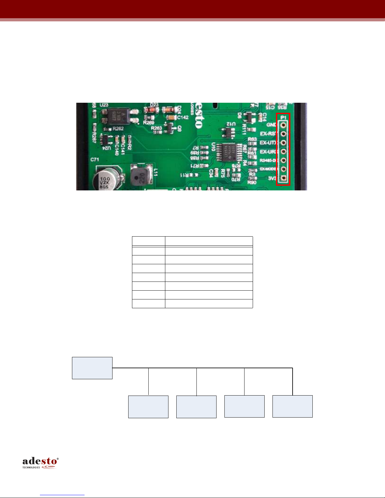
3.1 Evaluate ASCII Pass-through Using the SM2400-EVK2
The SM2400-EVK2 can be used o evalua e ASCII pass- hrough by connec ing an RS232 device o he hos in er-
face P1 header on he base board of he SM2400-EVK2 as shown below.
Figure 1.
P1 Header on the SM2400-EVK2 Base Board
3.2 Re lacing the RS485 Bus with Power Line via SM2400-EVK2 with ASCII Pass-through
This sec ion shows he difference be ween he older RS485 bus ne work (Figure 2) and he newer RS485 bus ne -
work wi h RS232 devices (Figure 3) and RS485 devices (Figure 4).
Figure 2.
Old RS485 Bus Network
Table 1. P1 Header Pin List
Pin# Name
P1 3V3
P2 Mode1
P3 RS485 Da a Enable
P4 EX_UART_RX
P5 EX_UART_TX
P6 Rese
P7 GND
Mas er
Slave 1 Slave 2 Slave 3 Slave 4
RS485 Bus

6SM2400 Serial- o-PLC Adap er User’s Guide
UG-SM2400–-177A–-02/2019
Figure 3.
New Power Line RS485 Bus Network with RS232 Devices
Figure 4.
New Power Line RS485 Network with RS485 Devices
SM2400
EVK2
SM2400
EVK2
SM2400
EVK2
SM2400
EVK2
SM2400
EVK2
Power Line
RS232
Slave 1
RS232
Slave 2
RS232
Slave 3
RS232
Slave 4
RS232
Mas er
S M 240 0
EVK2
S M 2400
E V K 2
S M 240 0
EVK2
S M 240 0
EVK2
S M 24 00
EVK2
P ow er L ine
R S 2 32 o
R S 48 5
R S 2 32 o
R S 48 5
R S 2 32 o
R S 48 5
RS232 o
R S 48 5
R S 2 32 o
R S 48 5
R S 48 5
Slave 1
R S 48 5
Slave 2
R S 4 85
Slave 3
R S 48 5
Sla ve 4
R S 23 2
M as er

7SM2400 Serial- o-PLC Adap er User’s Guide
UG-SM2400–-177A–-02/2019
4. ASCII Pass-through Configurations
This sec ion describes he suppor ed fea ures of he ASCII pass- hrough configura ion, including AT commands,
AT regis ers, baud ra es, and fac ory defaul s.
4.1 Su orted AT Commands
Table 2 lis s he suppor ed AT commands.
No e: When running ASCII pass- hrough firmware for he firs ime, i is impor an o run he AT&F command fol-
lowed by he ATZ command. This is required o wri e ASCII-specific defaul se ings o he Flash memory.
4.2 Su orted AT Registers
Table 3 lis s he suppor ed AT regis ers.
No e ha regis er numbers 100 and above may be used for advanced physical-level PLC configura ion. The al era-
ion of hese parame ers from heir defaul values is usually no required. However, in challenging circums ances,
e.g. high in erference or noise, his may be an op ion. The applicabili y and meaning of such se ings depends on
he PLC pro ocol. For more informa ion, refer o he documen s lis ed in Sec ion 7, References, or con ac Semi-
ech Semiconduc ors should fine uning of he physical parame ers be required.
Table 2. Su orted AT Commands
Command Descri tion
+++ Swi ch o command mode.
ATO Swi ch o da a (s ring x) mode; his command ends wi h Sa in le er "O", no wi h zero.
ATSr? Ge Regis er r.
ATSr= Se Regis er r.
ATZ Reboo device.
AT&F Res ore Fac ory Defaul s (mos defaul s depend on PHY, see below).
AT&MBM Make mas er.
AT&MBS Make slave (requires address as argumen ).
AT&MBC Run given command.
Table 3. Su orted AT Registers
Register Number
37 UART baud ra e (37 is s andard alloca ion for his purpose).
100-200 PLC PHY configura ion parame ers.
100 Modula ion code, 0 o 6.
101 Bi s per baud.
102 Number of repe i ions.
103 Number of frequencies.
104 Convolu ion code enable.
1: enable
0: disable
105 Tone map. A bi map con aining a lis of he sub-bands (groups of ones) ha are ei her ac ive (bi se o 1) or
inac ive (bi se o zero). A bi in he bi map represen s a group of consecu ive ones and he number of ones
per group depends on he band plan.
106 Coheren mode.
1: enable
0: disable

8SM2400 Serial- o-PLC Adap er User’s Guide
UG-SM2400–-177A–-02/2019
4.3 Su orted Baud Rates
Table 4 defines baud ra es, which can be applied o UART using ATS command wi h regis er number 37 (conven-
ional regis er for se ing he baud ra e).
Example:
ATS37 = 14: baud ra e se o 57600
ATS37 = 16: baud ra e se o 230400
4.4 Factory Defaults
Following are he defaul PLC parame ers wi h ASCII pass-through or TP pass-through firmware, which are acces-
sible for modifica ion via AT commands in ASCII pass-through varian s.
107 Delimi er.
0: SOF no response
1: SOF w/ response
2: ACK
3: NACK
108 On/Off mode.
1: enable
0: disable
109 Band selec ; XR-specific se ing
110 SubCarriers; 4 decimal conca ena ed numbers, e.g. se of subcarriers "30 40 50 60" is encoded as 30405060.
111 FCC enable (XXR pro ocol).
1: enable
0: disable
Table 4. Su orted Baud Rates
Mode Baud Rate
0 hrough 4 600
5 1200
6 2400
7 and 8 4800
9 9600
10 and 11 14400
No e: These higher baud ra es migh no be s andard alloca ions
12 19200
13 38400
14 57600
15 115200
16 230400
17 375000
18 625000
Table 3. Su orted AT Registers (continued)
Register Number

9SM2400 Serial- o-PLC Adap er User’s Guide
UG-SM2400–-177A–-02/2019
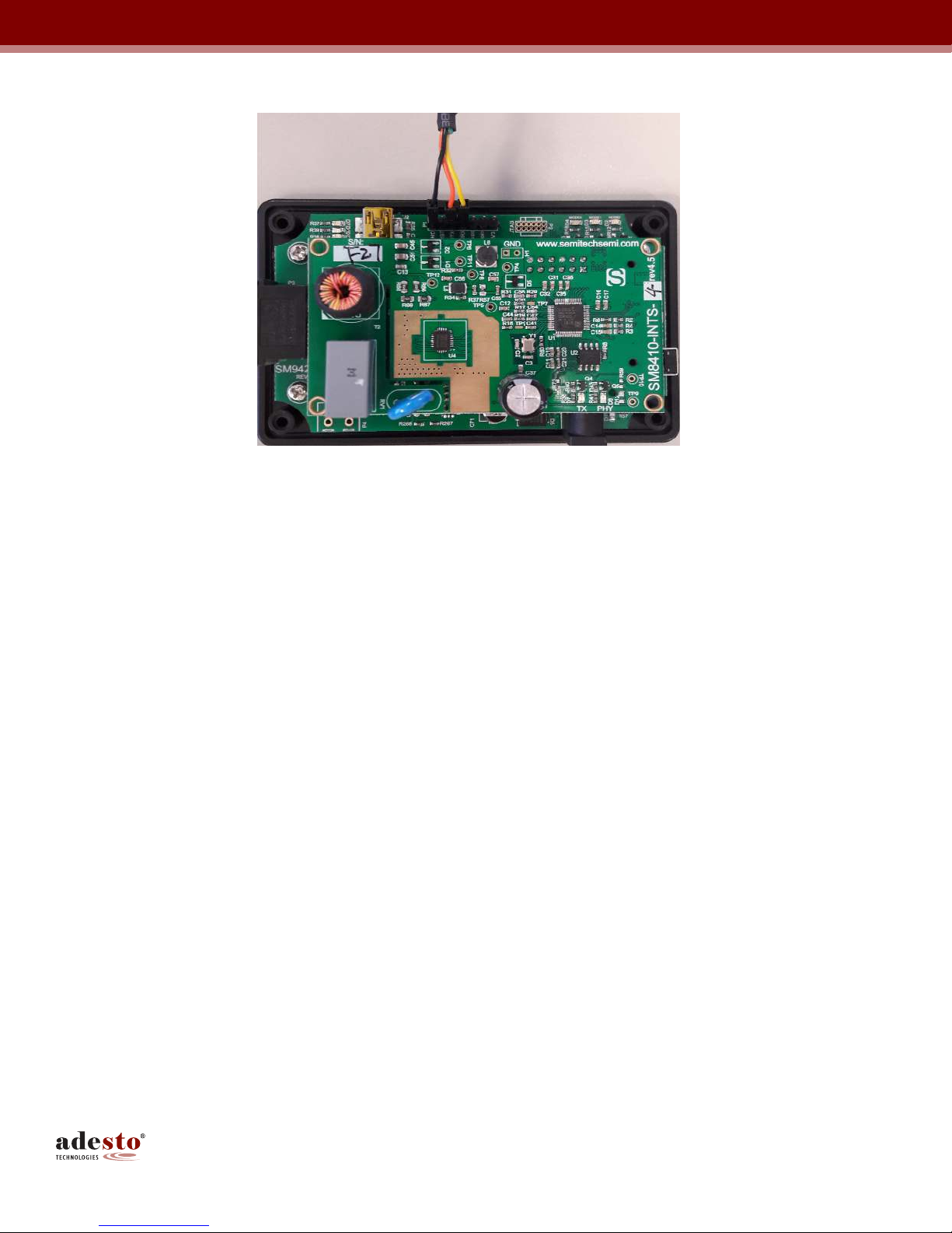
5. ASCII Pass-through Using USB to TTL RS232 Ada tor with SM2400-EVK2
ASCII pass- hrough can also be es ed using a USB o TTL RS232 adap er connec ed o he hos in erface connec-
or P1 on he base board of he SM2400-EVK2 as described in he op por ion of Figure 5 below.
5.1 Hardware Connection
The connec ion o he UART por is available on he SM2400-EVK2M base board on he header P1, where pin 5 is
ex ernal ransmi , pin 4 is ex ernal receive, and pin 7 is ground as shown below.
This UART por can be connec ed ei her direc ly o he TTL-level UART por on he hos device (if available), or o
a USB por via a USB- o-UART conver er, also known as FTDI (Digikey Par No. 768-1204-ND). The la er me hod
of he connec ion is illus ra ed by Table 6 and Figure 5.
Please no e ha he mini-USB cable and he FTDI cable can' be used a he same ime.
Table 5. Factory Defaults
Parameter/Mode Default
UART baud ra e 115200 (mode 15)
XXR Modcod = 1
bi sPrBaud = 1
repe i ion = 4
Subc2200 = 30405060
G3 Modcod = 0
Bi sperBaud = 1
Repe i ions = 4
ToneMap = 0x03F
Coheren = 1
Delimi er = 0
Table 6. Connecting the FTDI Device to the SM2400-EVK2 Base Board
FTDI TTL-232R-RPi SM2400-EVK2 Base Board
RXD (Yellow cable) EX_UART_RX
(Pin 4 of P1 Header)
TXD (Orange cable) EX_UART_TX
(Pin 5 of P1 Header)
GND (Black cable) GND
(Pin 7 of P1 Header)
10SM2400 Serial- o-PLC Adap er User’s Guide
UG-SM2400–-177A–-02/2019
Figure 5.
FTDI TTL-232R-RPi Connection
5.2 Download ASCII Pass-through Firmware
The
img-passthru-g3-ascii-fcc
bundle can be downloaded o he SM2400-EVK2 FCC module using he
SM2400Con rol GUI as described in he SM2400-EVK User Guide.
If an FTDI cable is used for downloading, pin 1 (3V3) and pin 2 (Mode1) of header P1 mus be connec ed via a
jumper o pull he Mode1 pin high for downloading. This jumper is shown in Figure 6 below. Af er he download is
comple e, remove he jumper and power cycle he SM2400-EVK2.
If a mini-USB cable is used for downloading, here is no need o manually con rol he Mode1 pin because i is con-
rolled by he CP2110 on he SM2400-EVK2 base board.

11SM2400 Serial- o-PLC Adap er User’s Guide
UG-SM2400–-177A–-02/2019
Figure 6.
- FTDI TTL-232R-RPi Connection for Downloading
5.3 Send Text Message Using a Serial Terminal
Af er downloading he ASCII pass-through firmware o wo SM2400-EVK2 sys ems, he ASCII messages can be
sen be ween hose wo EVK sys ems over he power line via a serial erminal, e.g. Bray's Terminal
(h ps://si es.google.com/si e/ erminalbpp/). This can be accomplished using he following procedure.
1. Connec each SM2400-EVK2 o a PC using he FTDI TTL-232R-RPi cables as shown below.
Figure 7.
Connecting Each SM2400-EVK2 to a PC
2. S ar Terminal.exe
SM 24 00-
E V K 2
SM2400-
E V K 2
P o w er Line
TT L-232R
R P i C able
TT L-232R
R P i C able
12SM2400 Serial- o-PLC Adap er User’s Guide
UG-SM2400–-177A–-02/2019
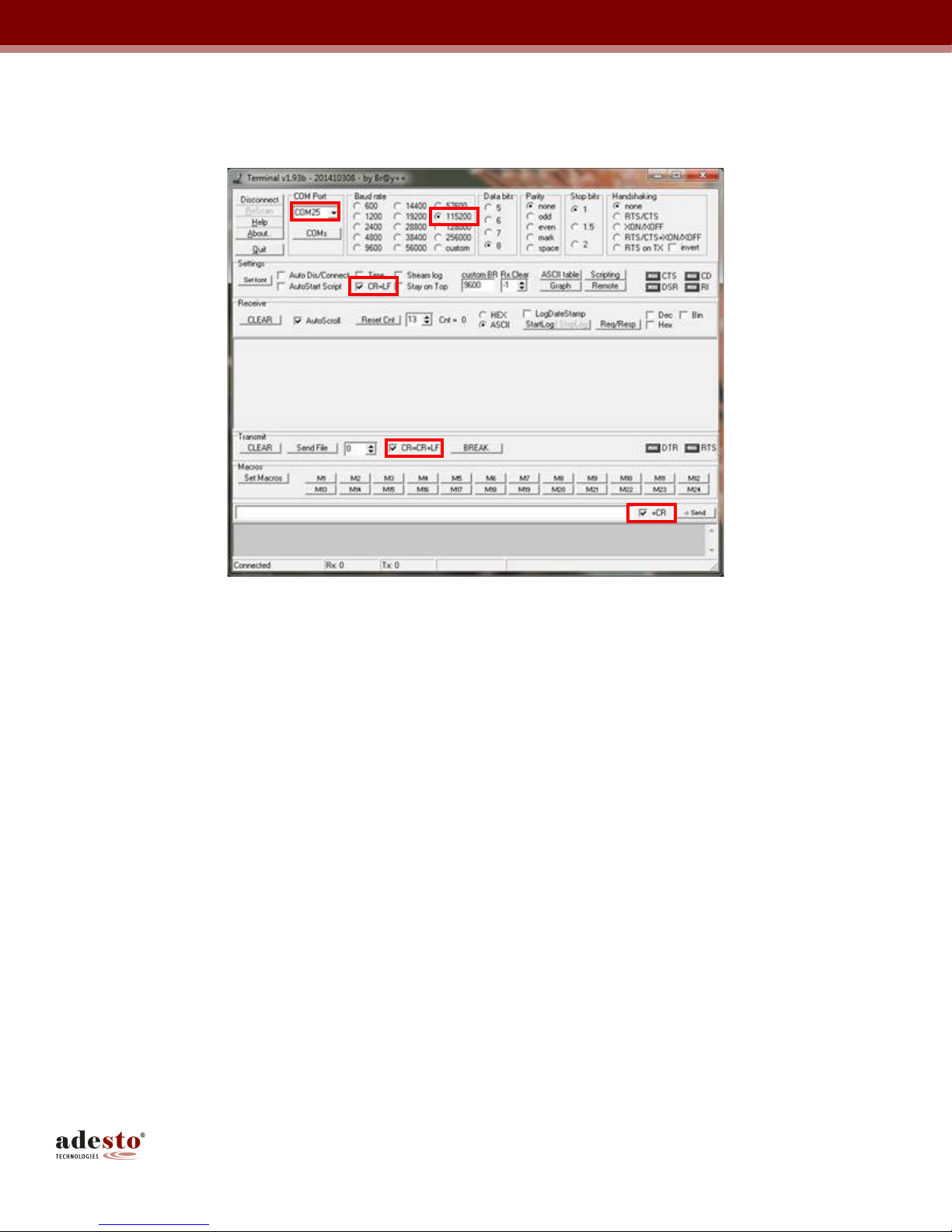
3. Once he erminal.exe program is invoked, connec he EVK o he erminal via he righ COM por a a defaul baud
ra e of 115200 as shown in Figure 8.
Figure 8.
Set the Baud Rate to 115200
4. When running he ASCII PASSTHRU projec for he firs ime on he board, which had o her projec s loaded before, i is
impor an o run AT&F command followed by ATZ command. This is needed o wri e ASCII-specific defaul se ings o
flash.
5. Send ATO o swi ch o da a mode.
6. Repea s eps 2 hrough 4 for he second SM2400-EVK2.
7. Tes any ASCII s ring from one erminal and i should be received and displayed on he 2nd erminal as shown in
Figure 9.

13SM2400 Serial- o-PLC Adap er User’s Guide
UG-SM2400–-177A–-02/2019
Figure 9.
Send Hello World from Terminal 1
Figure 10.
Received from Terminal 2 with Retries

14SM2400 Serial- o-PLC Adap er User’s Guide
UG-SM2400–-177A–-02/2019
6. Exam le A lication
The following example illus ra es an off- he-shelf RS485 sensor (inclinome er) managed remo ely by in roducing
wo PLC adap ers be ween he sensor and he PC based GUI in a plug-and-play manner as shown in Figure 11.
The scope image in Figure 12 shows he message propaga ion from he sensor o he PC and back.
Figure 11.
RS485 Inclinometer Exam le Configuration
Figure 12.
RS485-to-PLC Message Pro agation
SM2400-EVK2 SM2400-EVK2
15SM2400 Serial- o-PLC Adap er User’s Guide
UG-SM2400–-177A–-02/2019
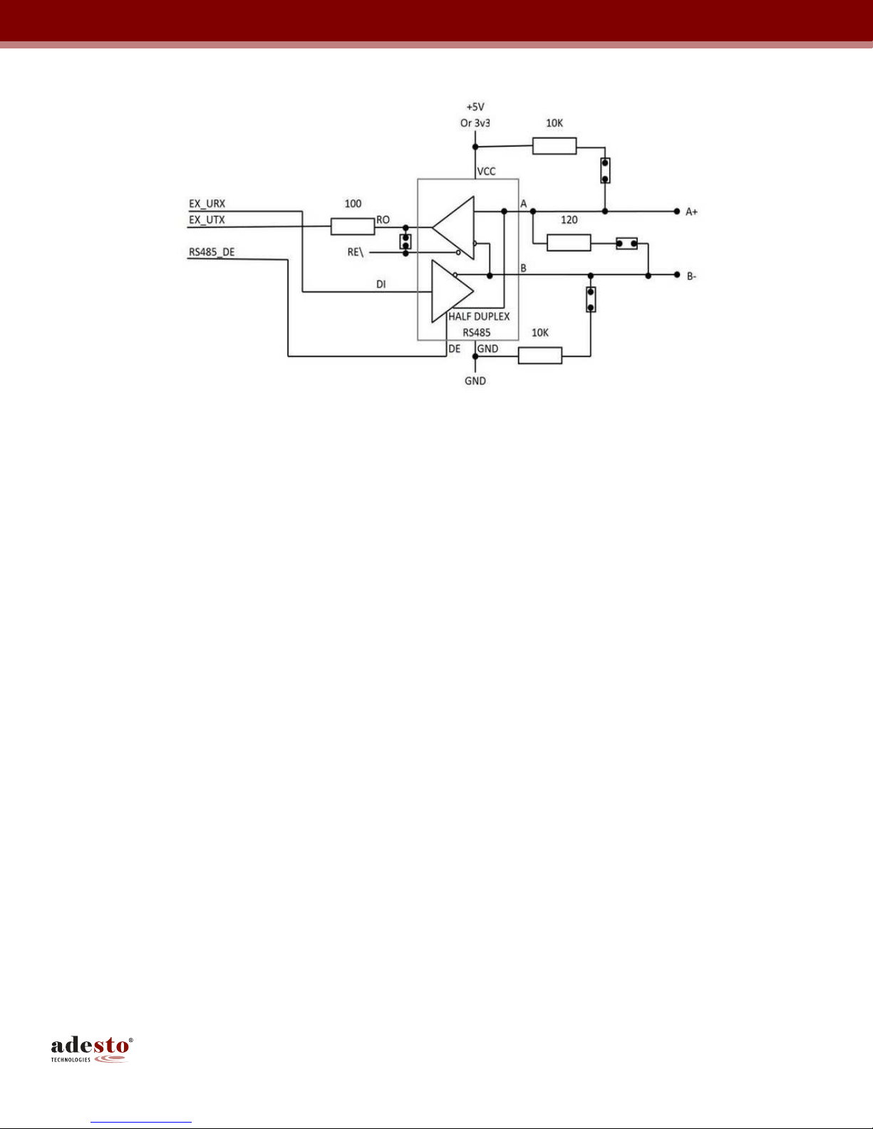
Figure 13.
RS485 Transceiver Circuit to the SM2400-EVK2
7. References
1. Narrowband OFDM PLC specifica ions for G3-PLC ne works, G3-PLC Alliance, April 2015
2. Specifica ion for PoweRline In elligen Me ering Evolu ion, revision 1.4, Prime Alliance 2014

Cor orate Office
California | USA
Ades o Headquar ers
3600 Pe erson Way
San a Clara, CA 95054
Phone: (+1) 408.400.0578
Email: con ac @ades o ech.com
© 2019 Ades o Technologies. All righ s reserved. UG-SM2400--177A–-02/2019
Ades o, he Ades o logo, CBRAM and Da aFlash are rademarks or regis ered rademarks of Ades o Technologies Corpora ion in he Uni ed S a es and o her coun ries. O her company, produc , and service
names may be rademarks or service marks of o hers. Ades o produc s are covered by one or more pa en s lis ed a h p://www.ades o ech.com/pa en s.
Disclaimer: Ades o Technologies Corpora ion (“Ades o”) makes no warran ies of any kind, o her han hose expressly se for h in Ades o’s Terms and Condi ions of Sale a h p://www.ades o ech.com/
erms-condi ions. Ades o assumes no responsibili y or obliga ions for any errors which may appear in his documen , reserves he righ o change devices or specifica ions herein a any ime wi hou
no ice, and does no make any commi men o upda e he informa ion con ained herein. No licenses o pa en s or o her in ellec ual proper y of Ades o are gran ed by Ades o herewi h or in connec ion wi h
he sale of Ades o produc s, expressly or by implica ion. Ades o’s produc s are no au horized for use in medical applica ions (including, bu no limi ed o, life suppor sys ems and o her medical
equipmen ), weapons, mili ary use, avionics, sa elli es, nuclear applica ions, or o her high risk applica ions (e.g., applica ions ha , if hey fail, can be reasonably expec ed o resul in personal injury or
dea h) or au omo ive applica ions, wi hou he express prior wri en consen of Ades o.
Other manuals for SM2400-EVK2
1
Table of contents


