Adexa RGR36X User manual

Page 1
GB
Models:
RGR36X RGR24X
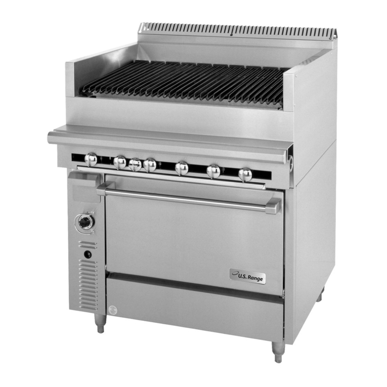
GAS RANGES WITH OVEN
Installation and operation manual
Important:
1. You are advised to read these instructions first before installation commences.
2. This manual must be handed to the end user after installation and commissioning.
3. These instructions are only valid if the country code appears on the appliance. If the code does not appear on the appliance, refer to the technical
instructions for adapting the appliance to the conditions for use in that country.


Page 2
Index
Technical specifications………………………………………………………… 4
1. General information ………………………………………………............… 7
2. Safety …………………………………………………………...............………7
Using the appliance safely
Safety instructions in case of malfunction
Additional prohibitions (hazardous procedures)
Disposing of the appliance
3. Functional description……………………………………………............…8
Application of the appliance
Prohibited use
Construction
Construction features
Cooking surfaces
Electric oven
4. Installation…………………………………………………………............… 9
General information
Regulatory installation conditions
Exhausting fumes
Possible environmental interference
Preparing for installation
Storage
Transporting the appliance
Unpacking the appliance
Disposing of packaging materials
Positioning the appliance
Gas supply connection
Electrical connection
Checking gas supply pressure after installation
Gas technical specifications
Checking operation
Staff training
Rating plate

Page 3
5. Adjustment instructions………………………………………..............… 13
Replacing open burner nozzles
Replacing the nozzle of open burner pilot flames
Adjusting minimum output
Functional check
6. Operating instructions…………………………………………….............. 15
Before using the appliance
Preparing the appliance for use
Using the appliance
Operating controls
Turning the open burners on and off
Turning on the electric oven
After-use care
Cleaning
Idle period
Periodic maintenance
7. Failure Analysis & Troubleshooting………………………………………19

Page 4
Technical specifications
a. Installation drawings
RGR36X
b. Technical specifications table
Model Dimension(mm)
Gas Range orifice size & heat input
G30 G20 G25.3
29mbar 37 mbar
50 mbar
20 mbar
25 mbar
RGR36X 914*855*1524
1.3mm 1.2mm
1.1mm
1.9mm
1.9mm
36kW 36kW 39kW 36kW 36kW
RGR24X 609*855*1524
1.3mm 1.2mm
1.1mm
1.9mm
1.9mm
24kW 24kW 26kW 24kW 24kW
Model
Oven Dimension
(mm)
OVEN orifice size & heat input
G30 G20 G25.3
29mbar 37 mbar
50 mbar 20 mbar 25 mbar
RGR36X 670x660x350 1.5mm 1.4mm 1.3mm 2.2mm 2.2mm
8.5kW 8kW 8kW 7.2kW 7kW
RGR24X 520x660x350 1.5mm 1.4mm 1.3mm 2.2mm 2.2mm
8.5kW 8kW 8kW 7.2kW 7kW

Page 5
d. Exploded Drawing
RGR36X

Page 6
Part list
SN Part Name Qty SN Part Name Qty
1 Chimney assy 1 28
¢10 nut 13
2 Guide trough for rear protect plate 2 29 φ10 oval clamp 14
3 rear plate assy 1 30 orifice connector 6
4 grate 6 31 orifice fixation plate 6
5 short burner assy 6 32 orifice 7
6 stove body assy 1 33 orifice connector nut 7
7 left side plate 1 34 ¢8 nut M14X1.25 1
8 oven thermostat knob scale 1 35 ¢8 clamp 4
9 zinc knob with insert 1 36 orifice angle connector 1
10 inspection plug for gas inlet pipe 1 37 pilot rack 1
11 flame knob 6 38 thermocouple rack 1
12 Front control panel 1 39 oven thermocouple 1
13 oven door assy 1 40 pilot 1
14 left door decoration bar 1 41 U burner 1
15 front bottom hinge assy 2 42 1/4 to ¢10 transfer connector 1
16 bottom door decoration bar 1 43 CE11 sabaf valve 6
17 crumb tray assy 1 44 valve prolong connector 6
18 gas inlet pipe 1 45 NPT1/8 to ¢10 transfer connector 6
19 oven chamber assy 1 46 ¢6 nut M10x1 1
20 adjustable foot 4 47 ¢6 clamp 3
21 door hinge assy 2 48 thermostat rack B 1
22 right door decoration bar 1 49 ¢8 nut M13x1 1
23 right side plate 1 50 thermostat rack A 1
24 V baffle plate 1 51 thermostat valve with micro switch 1
25 oven chamber bottom plate 1 52 NPT1/8 to ¢10 transfer angle connector 1
26 wire net in chamber 2 53 stove thermopile 6
27 grill supporter 4

Page 7
1. General information
Read the instructions in this manual carefully, as they contain important information on how to install, use and service the appliance
safely, properly, and effectively.
Keep this manual in a safe place so that it can be used as reference by other operators of the appliance.
This appliance should be installed following the instructions provided by the manufacturer and in compliance with all applicable
local regulations. This appliance should be connected to the gas supply by qualified personnel only.
All personnel in charge of using this appliance should be specifically trained in its operation.
In the event of failure or malfunction, switch off the appliance. The periodic functional checks requested in this manual should be
carried out according to the instructions. Have the appliance serviced by a technically qualified person duly authorized by the
manufacturer that uses genuine spare parts.
Failure to comply with the above may jeopardize the appliance’s safety.
2. Safety
2.1 Using the appliance safely
The appliance is designed only for professional use, it should be operated by qualified personnel exclusively.
This appliance is not intended for use by persons (including children) with reduced physical, sensory or mental capabilities, or lack of
experience and knowledge, unless they have been given supervision or instruction concerning use of the appliance by a person
responsible for their safety.
Children should be supervised to ensure that they do not play with the appliance.
Never leave the appliance unattended while it is operating.
Do not move the appliance while it is hot.
2.2 Safety instructions in case of malfunction
If the appliance will remain idle for some time or in the event of a failure, abnormal operation, etc., please switch off the control valve of
the appliance and shut off the main gas valve on the pipeline. Call the service center if the appliance cannot work properly.
2.3 Additional prohibitions (hazardous procedures)
Never tamper with the seals of the adjusting screws located on the gas valves.
2.4 Disposing of the appliance
This appliance has been manufactured using recyclable raw materials and does not contain any hazardous or toxic substances. To
dispose of the appliance or its packaging materials, strictly follow the local regulations in force in the place where it is installed.
Packaging materials should be divided according to the material type and delivered to a specific collection site. Ensure it is in compliance
with the environmental protection regulations.
3. Functional description
3.1 Application of the appliance
The appliance is designed for use in the gastronomy and confectionery industries only.

Page 8
3.1.1 Prohibited use
The manufacturer cannot be held liable for any faults caused by defective installation or inappropriate use of the appliance. In such
cases, the warranty shall be null and void.
3.2 Construction
3.2.1 Construction features
Supporting structure is made of SUS stainless steel.
Exterior finish and height-adjustable legs are SUS stainless steel.
Control panels are conveniently shaped and have controls slanted towards the operator.
3.2.2 Cooking surfaces
1. Unit RGR24X with 4 stabilized-flame gas burners made of cast iron and controlled by pilot flames;
Unit RGR36X with 6 stabilized-flame gas burners made of cast iron and controlled by pilot flames;
High-to-low output control;
Safety valves fitted with thermocouple ensure that gas flow will be immediately shut off in the event that a burner is extinguished
accidentally or a failure occurs;
Two-burner acid-resistant black enameled cast-iron grates;
Stainless steel drip pans.
3.2.3 Bottom oven
The temperature of the bottom oven can be adjusted by rotating the thermostat to the desired scale.

Page 9
The user can set the temperature according to different food. It is recommended that the normal working temperature should be
180--250℃. It would take approximately 22~26 minutes for the oven temperature to reach 250℃.
When the temperature reached the pre-set temperature, the thermostat would cut-off the power supply automatically.
When the temperature is lower than the pre-set value, the thermostat would restart working.
After finishing a day’s work, rotate the controlling knob to the OFF position.
4. Installation
4.1 General information
The manufacturer cannot be held liable for any damage to property or injury to persons deriving from installation errors or from
inappropriate use of the appliance and is not responsible for any faults caused by defective installation. In such cases, the warranty shall
be null and void.
The appliance should be installed, serviced, and started up only by an authorized installer, who must comply with the safety regulations
in force in the plac8
e where the appliance is being installed.
4.1.1 Regulatory installation conditions
For your information, we remind you that all appliances installed in public assembly buildings must meet all the requirements listed below.
The appliance should be both installed and serviced in accordance with all applicable regulations and standards in force, namely:
Safety regulations on fire hazard and panic in public assembly buildings.
General regulations applicable to all appliances;
Systems burning combustible gas and liquefied hydrocarbons.
Then, follow the specific regulations according to the type of gas being used.
Heating, ventilation, refrigeration, air conditioning, and generation of steam and hot water for sanitary use;
Installation of foodservice cooking appliances;
Specific regulations applicable to each type of public assembly building (hospitals, shops, etc.).
4.2 Exhausting fumes
The appliance should be installed in a well-ventilated area, if possible under a vent hood, in compliance with all applicable regulations in
force. This will ensure that the flue gas can be completely exhausted.
4.3 Possible environmental interference
If the appliance is installed with its sides next to flammable walls (made of wood or similar materials) or to heat-sensitive walls (made of
plasterboard or similar materials), suitable protective measures should be taken to keep such walls undamaged. Therefore, apply a
coating to insulate the walls from radiative heat or keep a minimum clearance of 200 mm (8") from the side and back panels of the
appliance.

Page 10
4.4 Preparing for installation
Check that the appliance is pre-set to use the gas family available at the place of use. If the available gas is different, you will need to
convert the appliance to use with other type of gas. For directions, please refer to section
"Adjustment instructions"
below.
4.5 Storage
If the appliance has been stored in a warehouse where room temperature is below 0°C (32°F), it should be warmed up to at least +10 °C
(50 °F) before switching it on.
4.6 Transporting the appliance
The best way to transport this appliance is inside its packing to protect it from outside damage. After the appliance has been unpacked,
use wooden spacers if you should need to lift it up.
4.7 Unpacking the appliance
Prior to installation, remove all packaging materials from the appliance. Certain parts are wrapped up in adhesive film, which should be
carefully removed. Remove any glue traces left on the appliance thoroughly using non-flammable solvents. It is forbidden to use abrasive
substances.
4.8 Disposing of packaging materials
All packaging materials must be disposed of in compliance with applicable local regulations in force where the appliance is being
installed. Packaging materials should be separated according to their types and delivered to specific collection sites. Ensure compliance
with environmental protection regulations.
4.9 Positioning the appliance
Position the appliance in a level and stable place. Height can be adjusted with the help of the adjustable feet.
4.10 Gas supply connection
This appliance is designed to burn natural and liquid gas. To find out the category to which this appliance belongs in the country where it
is installed, please refer to the table below.
Do not use any accessory or spare parts that have not been recommended or designated by the manufacturer. This can pose a danger
for the user or lead to damages of the appliance or personal injury.
Do not leave the unit unattended during operation.
Never move or reposition the unit until the unit cools down completely. WARNING! Risk of injury! Touch with hot plate may cause burns
at hands and face!
The chamber of bottom oven may be quite hot during operation. Keep your hands off the cooking chamber.

Page 11
Table 1: gas categories and pressure values
COUNTRY APPLIANCE
CATEGORY GAS RATED PRESSURE
(mbar)
MINIMUM PRESSUR
E
(mbar)
MAXIMUM
PRESSURE
(mbar)
IT GB BE
CH CY CZ
CZ ES FR
LT SK PT
IE GR
I3+
G30 29 25 35
G31 37 25 45
AT BE DE
IT CH NO
PT ES SE
I2H G2 20 17 25
DE GR AT
CH SI I3B/P G30 50 42.5 57.5
BE FR LU I2E G20 20 17 25
The appliance should be connected to the gas supply by means of metal pipes --either rigid or flexible-- having an adequate diameter.
When joining pipe fittings, never use oakum or Teflon as their residues could get into the valve and jeopardize its operation. Instead,
interpose a seal gasket suitable for using in gas systems. Do not forget to fit a shutoff valve on the gas supply line upstream of the
appliance, which should be closed whenever the appliance is not in operation.
After connecting the appliance to the gas system, check for leaks at joints and pipe fittings; to do so, use soapy water or a specific leak
detector (spray).
4.11 Checking gas supply pressure after installation
Gas supply pressure can be measured with a liquid-filled pressure gauge (for example, a U-shaped pressure gauge, minimum scale
division 0.1 mbar) or a digital gauge. Proceed as follows:
Remove the left grate, burners, and drip pan;
Unscrew the screw on the pressure port
Place the pressure gauge;
Start up the appliance by following the instructions in the user’s manual;
Check supply pressure;
If the measured pressure value is within the range shown in
"Table 1: gas categories and pressure values"
, the appliance can be
started up. Otherwise, contact the gas utility company.
Remove the pressure gauge;
Replace the sealing screw;
Check for leaks.

Page 12
1. Gas ramp
2. Pressure port
3. Pressure port sealing screw
4.12 Gas technical specifications
The appliance should be started up at its rated output with the nozzles shown in
"
Technical specifications table
"
. All the necessary
nozzles are provided in a small bag together with the appliance. The nozzles of the main burners are marked in hundredths of mm, while
those of pilot flames have a reference number.
4.13 Checking operation
1. Start up the appliance by following the instructions given in chapter
"Using the appliance"
;
2. Check for gas leaks;
3. Check for flame stability throughout the whole control range by going from high to low.
4.14 Staff training
Inform all personnel assigned to operate the appliance on how to use it by referring to this user’s manual and hand them out the manual.
4.15 Rating plate
The rating plate showing the specifications of the corresponding model is applied in the position shown in the installation and connection
drawings and includes the data listed below:
5. Adjustment instructions
To convert (for example) from natural gas to liquid gas, you need to change the nozzles of main and pilot burners. The appropriate
nozzles are shown in Technical specifications table.
Table 2: pilot burner specifications

Page 13
Gas Type Oven Pilot
Nozzle NG
Oven
Pilot Nozzle
LPG
RGR36X 0.4mm 0.25mm
RGR24X 0.4mm 0.25mm
Note: When replacing the nozzles, please follow the requirements described in the table. If the gas type is not listed in the table, please
contact the manufacturer or supplier directly.
5.1 Replacing open burner nozzles
Remove the grate, the flame spreader, the burner and the drip pan;
Unscrew the screw that fixes the primary air sleeve and remove the sleeve;
Unscrew the nozzle using a 10-mm spanner and fit a suitable nozzle (refer to Technical specifications table).
5.5 Adjusting minimum output
If the appliance will be using liquid gases, remove the knobs, insert a screwdriver through the hole and completely screw down the
screw.
For other types of gas, you will need to adjust the screw as required until you obtain a stable and even flame. Proceed as follows:
Unscrew the screw;
Connect a liquid-filled pressure gauge (for example, a U-shaped pressure gauge, minimum scale division 0.1 mbar) or a digital
gauge;
Start up the appliance by following the instructions in the user’s manual;
Gas pressure at minimum burner output should match the pressure values under “Reduced pressure (mbar), minimum”.
5.6 Functional check
Start the appliance by following the
"Operating instructions"
;
Check for leaks;
Check for flame stability throughout the ON-OFF-ON control range;
Check the lighting process along the main burner and check that flames are even;
Check for proper operation of pilot flame;
Check that flue gases come out of the corresponding pipes regularly;
Check that there is a good inflow of fresh air.
6. Operating instructions
6.1 Before using the appliance
6.1.1 Preparing the appliance for use

Page 14
Before cooking food for the first time, we recommend cleaning the appliance thoroughly, and especially the oven cooking chamber.
Remove all packaging materials and adhesive films from the appliance very carefully. Before cleaning the stainless steel parts, make
sure that the detergent you intend to use does not contain any abrasive substances and that it is suitable for stainless steel surfaces.
Wipe the appliance dry with a clean cloth.
Never use water jets to clean the appliance.
6.2 Using the appliance
6.2.1 Operating controls
By way of example, below is represented one of the most comprehensive appliances in this family.
6.2.2 Turning the open burners on and off
6.2.2.1 Please read this manual carefully before using.
6.2.2.2 Verify fuel gas type. Ensure that the fuel type matches the nameplate specification.
6.2.2.3 For initial startup, press and turn the knob to nine o’clock position and hold it to purge all the air in the piping. It
may take about 10 seconds.
6.2.2.4 Light it with long match lighter, hold the knob 10 seconds,until the flame is stable. Adjust the knob to high flame
position “ ” for complete ignition of the main burner. The flame can be adjusted basing upon the requirements.
If failed, repeat above steps.
6.2.2.5 After using, turn the knob clockwise to the “OFF” position for complete shutdown of the main burner.
6.2.3 Turning on the oven
Ignition
To light the burner, press and turn the knob to the left “ ” position, press strongly again and light the pilot burner with a slow fire. Keep on
pressing the knob for about 20seconds and leave it, pilot flame with light. If not, repeat the ignition procedure. (For first time, the light time
may be longer.)
◆
Release the knob 20 seconds after the pilot flame is ignited.
◆
Turn the control knob to the corresponding temperature as needed, (adjustable between 150℃and MAX), after the temperature reaches
the setting temperature, the flame will flameout automatically, if the temperature drops, the burner will restart to work.
Flameout
◆
Turn the control knob to “OFF”
◆
Cut off the main air supply
thermostat valve knob scale

Page 15
NOTICE:
An unpleasant smell the very first time it is operated can be considered as completely normal.
In fact, this is due to the overheating of insulating materials and residues of oil used during the metal working process. The first time you
turn the oven on, don’t place any food in the cooking chamber and set the temperature to 330°C until the smell disappears.
Below are the average temperatures at the center of chamber of the oven corresponding to each knob position.
1. 50 °C.
2. 100 °C
3. 150 °C
4. 200 °C
5. 250 °C
6. 300 °C
6.3 After-use maintenance
6.3.1 Cleaning
Before cleaning, turn off the appliance, shut off gas supply and electric supply upstream of it.
General information
The main causes for stainless steel wear or corrosion are:
Using abrasive or acid detergents, especially chlorine-based products such as hydrochloric acid or sodium hypochlorite (bleach).
Therefore, before buying a detergent product, make sure it does not corrode stainless steel
Stagnation of ferrous deposits (such as those created by rust dissolved in the water flowing through the piping, especially after the
appliance has remained idle for some time). Therefore, avoid such stagnation; do not use wire wool pads to remove the most
stubborn food residues. Use, rather, pads or spatulas made of stainless steel or softer, non-ferrous materials;
Stagnation of substances having acid components such as vinegar, lemon juice, sauces, salt, etc. Therefore, prevent prolonged
contact of these substances with the stainless steel parts of the appliance. The evaporation of saline solutions over the surfaces of
the appliance is particularly harmful to them.
Routine cleaning
Cleaning the appliance thoroughly every day will keep it in perfect condition and increase its lifetime. Clean the appliance with a damp
cloth using water and soap or detergents, provided that they are not acid or abrasive as discussed further above. Such detergents should
not even be used to wash the floor near the appliance, as their fumes may deposit on the steel surfaces and damage them. Rinse it off
with clean water and wipe it dry with a clean cloth. Do not rub the appliance with steel wool pads as they could leave rust stains. For the
same reason, avoid touching the appliance with ferrous objects.
Never use direct water jets to clean the appliance because this could result in water entering into it and damaging it.
Stains and abrasions on the steel surface
Scratches and dark stains may be smoothed or removed using stainless steel wool pads or synthetic abrasive sponges, which should
always be rubbed in the same direction as the satin finish.

Page 16
Rust
Should you need to eliminate rust stains, contact manufacturers of industrial detergents to find a detergent that can remove such stains.
Industrial descaling products can also be used to that end. After rubbing off the stain and rinsing with clean water, an alkaline detergent
may be required to neutralize any acid compounds left on the surface.
6.3.2 Idle period
If the appliance will remain idle for a certain period of time, clean it and wipe it dry first, and then apply a film of a suitable product (such
as Vaseline oil spray or similar products) to protect it. Shut off gas and power supply upstream of the appliance.
To avoid the appearance of corrosion spots, make sure that any salt residues left on the internal and external walls are carefully
removed.
6.3.3 Periodic maintenance
Only qualified personnel are allowed to carry out service and maintenance operations.
The following maintenance operations should be performed at least once a year:
Checking for proper operation of all control and safety devices;
Checking burner combustion, i.e.:
1. ignition;
2. combustion safety;
3. checking for proper operation throughout the entire HIGH-to-LOW control range.
We recommend signing a service agreement providing for at least one check-up a year.
7. Failure Analysis & Troubleshooting
7.1 Gas
Users are not allowed to perform any maintenance operations on any parts of this appliance. Maintenance should be carried out by an
authorized technician.

Page 17
Aforementioned failures are just for reference. If any failure occurs, please stop using and inform professional technician
to check and repair!

ADEXADIRECTLIMITED
GROUNDFLOORUNIT1214PURLEYWAYCROYDONCR04XGLONDONUNITEDKINGDOM
ECDeclarationofConformity
AdexaDirectLimiteddeclaresthat:
EquipmentType: Gasrangeswithoven
Model:RGR24X,RGR36X
ImportedBy:ADEXADIRECTLIMITED
GROUNDFLOORUNIT1214PURLEYWAYCROYDONCR04XG
LONDON,UNITEDKINGDOM
SerialNumber:
YearofManufacture:
Brand:ADEXA
ApplicationofCouncilDirective(s):(EU)2016/426(9March2016)
Standards:
EN203‐1,EN203‐2‐1,EN203‐2‐2
I,theundersigned,herebydeclarethattheequipmentspecifiedaboveconformstotheabove
Directive(s)andStandard(s).
Date: 20.10.2020
Signature:
FullName:HakanBaykal
Position:PurchaseManager
This manual suits for next models
1
Table of contents
Other Adexa Range manuals
