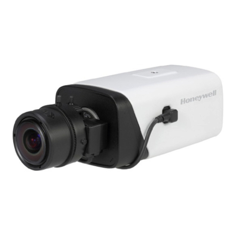
Honeywell VENTI Series User manual

Honeywell
VENTI Series
HICC-0100P/HICC-0100N Box Camera
User Guide

Revisions
Issue Date Revisions
A 11/03 New document for HICC-0100 release.
Generally describes the functionality in the
firmware of the HICC-0100 camera.

Honeywell
i
Contents
1About This Document ..................................................................................................1
Overview of Contents ..........................................................................................1
2Product Overview ........................................................................................................2
Features ..............................................................................................................2
Camera Parts and Definitions..............................................................................2
Camera Overview..........................................................................................2
Camera Parts and Definitions........................................................................3
3Installation and Connections........................................................................................5
Before You Begin ................................................................................................5
Unpack Everything ..............................................................................................5
Equipment Required............................................................................................5
Camera Installation .............................................................................................5
Checking Unpacked Camera.........................................................................6
Mounting........................................................................................................6
Network Camera Diagram .............................................................................6
Hardware and Software Requirements .........................................................6
Connecting the Camera to a Personal Computer................................................7
Setting IP.......................................................................................................7
Connecting the Camera to a Personal Computer..........................................7
Using “IP Finder” to Search Camera’s IP Address ..............................................9
4Overview of Navigation and Controls.........................................................................10
Live View...........................................................................................................10
Image Parameters.............................................................................................10
Basic ...........................................................................................................11
Compression ...............................................................................................13
Alarm...........................................................................................................17
OSD ............................................................................................................19
FTP Recording ............................................................................................19
SD Recording ..............................................................................................21
E-mail Recording.........................................................................................24
Audio ...........................................................................................................26
Network Settings ...............................................................................................27
Basic ...........................................................................................................27
Admin Function .................................................................................................31
Administrator ...............................................................................................31
User List ......................................................................................................31
Date/Time....................................................................................................32
Event Log ..........................................................................................................34
Information ........................................................................................................35
5Troubleshooting .........................................................................................................36
Technical Support .............................................................................................36
Problem: Lens out of Optical Focus ..................................................................36
6Specifications ............................................................................................................37
7Glossary ....................................................................................................................40

Honeywell
ii

Honeywell
i
Cautions and Warnings
Installation and servicing should be performed only by qualified and
experienced technicians to conform to all local codes and to maintain your
warranty.
12V DC/24V AC models require the use of CSA
Certified/UL Listed Class 2 power adapters to ensure
compliance with electrical safety standards. Power
over Ethernet (PoE) should meet the IEEE802.3af PoE
standards.
WEEE (Waste Electrical and Electronic Equipment).
Correct disposal of this product (applicable in the
European Union and other European countries with
separate collection systems). This product should be
disposed of, at the end of its useful life, as per applicable
local laws, regulations, and procedures.
Caution When powering the camera from 24V AC, a UPS source
should be considered to ensure satisfactory performance.
FCC Compliance Statement
Information to the user: This equipment has been tested and found to
comply with the limits for a Class B digital device, Pursuant to Part 15 of the
FCC Rules; these limits are designed to provide reasonable protection against
harmful interference in a residential installation. This equipment generates,
uses, and can radiate radio frequency energy and, if not installed and used in
accordance with the instruction manual, may cause harmful interference to
radio communications. However, there is no guarantee that interference will
not occur in a particular installation.

Honeywell
ii
If this equipment does cause harmful interference to radio or television
reception, which can be determined by turning the equipment off and on, the
user is encouraged to try to correct the interference. For example, try
reorienting or relocating the receiving antenna, increasing the separation
between the equipment and receiver, or connecting the equipment to an outlet
on a different circuit.
Caution
Changes or modifications not expressly approved by the party
responsible for compliance could void the user’s authority to
operate the equipment.
This Class B digital apparatus complies with Canadian ICES-003.
Manufacturer’s Declaration of Conformance
Europe
The manufacturer declares that the equipment supplied with this guide is
compliant with the essential protection requirements of EMC directive
2004/108/EC and General Product Safety Directive GPSD 2001/95/EC,
conforming to requirements of standards EN 55022 for emissions, EN
50130-4 for immunity.
Warranty and Service
Subject to the terms and conditions listed on the Product warranty, during the
warranty period Honeywell will repair or replace, at its sole option, free of
charge, any defective products returned prepared.
In the event you have a problem with any Honeywell product, please cal
Customer Service at 1.800.796.CCTV for assistance or to request a Return
Merchandise Authorization (RMA) number.
Be sure to have the model number, serial number, and the nature of the
problem available for the technical service representative.
Prior authorization must be obtained for all returns, exchanges, or credits.
Items shipped to Honeywell without a clearly identified Return Merchandise
Authorization (RMA)number may be refused.

Honeywell
1
1 About This Document
Thank you for purchasing HICC-0100P/N Box Camera.
This user guide is designed to be a reference tool for the installation and
operation your system including the camera’s features, functions and detailed
explanation of the menu tree.
Overview of Contents
This document contains the following chapters:
Chapter 2, Product Overview, introduces the main functions and system
requirements of the camera.
Chapter 3, Installation and Connections, provides detailed instructions on
installing the camera and connecting wires.
Chapter 4, Overview of Navigation and Controls, introduces how to
navigate in the main menu window and operate the controls.
Appendix A, Troubleshooting, lists common problems encountered when
setting up the network camera.
Appendix B, Specifications, provides specifications for the HICC-0100P/N
Box Camera.
Appendix C, Glossary, explains terms and initializations used in this guide.

Product Overview
2
2 Product Overview
Honeywell HICC-0100P/N box camera provide high quality image over a
network connection.
Table 2-1 Network Camera Model Numbers
Model Number Description
HICC-0100P CMOS Network Box, D1, H.264, PAL BNC output
HICC-0100N CMOS Network Box, D1, H.264, NTSC BNC output
Features
This chapter introduces the features and specifications of HICC-0100P/N Box
Camera.
1/4" color CMOS sensor
H.264, MPEG-4 and MJPEG compression
D1, CIF, QCIF, VGA, QVGA resolution
Dual digital video streams simultaneously, independently configurable
Supports both Dynamic and Static IP address assignment
Multiple levels of password protected remote access prevents unauthorized
users from altering system settings
Includes advanced IP Finder software to make system setup easy
Web server for remote setup of camera video and network parameters
Motion detection
Supports input and output alarm contacts
Local video out with BNC interface
Two-way audio
Supports video/audio multi-casting
Local storage in SD card
On-line firmware upgrade
DC12V, AC24V and IEEE 802.3af POE choice of power inputs
Camera Parts and Definitions
Camera Overview

Honeywell
3
Camera Parts and Definitions
1. CS mount: connect the lens with the camera
2. Screw
3. Back focus Adjustment
4. Base: connect the camera with the tripod
5. SD card slot: insert a SD card into this slot for recording and storage
6. Video: video output port

Product Overview
4
7. RJ45 Ethernet Connector/ PoE: insert the RJ45 cable for network
connection. It also supports PoE (Power over Ethernet).
8. Default: reset all of the camera parameters to factory default.
9. Reset Button: restart the system.
10. Power Indicator: Red light indicates power connection.
11. I/O Connector: Input/ Output Connector
12. Power Terminal: DC12V/AC24V, red port: power +/white port: power –/
black port: GND. Make sure to connect the power connector to correct ports (+
and –) when the power supply is DC12V.

Honeywell
5
3 Installation and Connections
This chapter describes the installation and connection of HICC-0100P/N Box
Camera.
Before You Begin
Please read this guide carefully before you install and operate the camera.
Unpack Everything
One HICC-0100P/N Camera
3-pin terminal block for power input, and 4-pin terminal block for alarm
input/ output
Quick Installation guide
One CD containing the software
Equipment Required
The following tools might help you to complete the installation:
Drill
Screwdrivers
Wire cutters
Camera Installation
Note All the installation and operations here should conform to your
local electricity safety rules.

Installation and Connections
6
Checking Unpacked Camera
When you receive the camera from the shipping agency, please check
whether there is any visible damage to its appearance. The protective
materials used for the package of the camera can protect most accidental
clashes during transportation. Then you can open the box to check the
accessories.
Please check the items in accordance with the list on the warranty card.
Finally you can remove the protective film of the camera.
Mounting
1. Attach the camera to a pending mount.
Insert the screws on the camera stand into either of the screw holes on the
base. Then tighten them up.
2. Mount the camera onto the ceiling/wall and fasten it securely.
Network Camera Diagram
Connection type1:
Connection type 2:
Hardware and Software Requirements
Computer
Windows XP or Windows 7 as OS
Internet Explorer Version 6.0-8.0
CPU: Intel Pentium IV X2 2.4 GHz or equivalent AMD
Memory: 1G or above
Display adapter
Support DirectX9 for example

Honeywell
7
4.1 NVIDIA GeForce 6 Series above
4.2 ATi Mobility Radeon 9500 above.
Power Supply
This camera requires a DC12V/AC24V /PoE power supply. Please make sure
you use the correct power supply before connecting to the camera.
Network Connector
Please use the RJ45 network connector for connecting the camera to your
computer or switch.
Switch
If you want to monitor several cameras, the switch is required.
Connecting the Camera to a Personal Computer
Setting IP
This is a network-based camera and must be assigned an IP address first.
1. Enter a default IP address manually. The camera’s default IP address is
192.168.0.30 and sub mask is 255.255.255.0.
2. Obtain an IP address automatically from the DHCP server. You don’t need
to change the camera’s IP address if your network uses a DHCP server.
Connecting the Camera to a Personal Computer
1. Connect the network cable to the camera and then turn on the camera’s
power.
2. Set the personal computer’s IP address. The camera’s default IP address is
192.168.0.30 and sub mask is 255.255.255.0.
3. Check that the camera and computer are connected by pinging the IP
address you have set. To do this, start a command prompt (Windows: from the
Start Menu, select Program. Then select Accessories and choose Command
Prompt.) Type “Ping 192.168.0.30”. If the message “Reply from…” appears, it
means the connection is done.
4. Start Internet Explorer and enter IP address: 192.168.0.30). A login window
will appear. Enter the default user name: admin and password: 1234 to log in.
Figure 3-1 Log on Screen

Installation and Connections
8
5. Images of the camera can be viewed through Internet Explorer. Before
viewing, follow these steps to enable the display.
a. Enable Cookies as shown below:
In Internet Explorer, click Internet Options on the Tools menu.
On the Privacy tab, move the settings slider to Low or Accept All
Cookies.
Click OK.
b. Set Browser setting when proxy server is used when a proxy server is
used.
c. Change Security in Internet options as shown below:
On tool menu, click Internet Option.
Press the Security tab.
If the camera operates inside the intranet, click the Intranet icon. If the
camera operates on the Internet, click the Internet icon.
Click Custom Level. This will open the Security Settings – Internet
Zone screen.
Scroll down to the ActiveX controls and plug-ins radio buttons and
enable all of them as shown in the illustrations:
Figure 3-2 ActiveX Controls and Plug-in Radio Buttons
Press OK to save the settings. Close all Internet Explorer Windows and
start a new window. This will allow the new settings to take effect.
6. Type your set IP address into the browser.
7. Then you should be able to see the camera image screen.

Honeywell
9
Using “IP Finder” to Search Camera’s IP Address
The IP Finder is a tool which helps users to find network cameras which you
currently monitor from your own computer. Please note that IP Finder is only
compatible with Windows 7, windows Vista and Windows XP.
1. Insert the CD in the CD-ROM drive.
2. Double click Honeywell_VENTI_IP_Camera(vx).exe to run the program.
Follow the instructions to install.
3. After successfully installing IP Finder, double click the IP Finder icon which
is displayed in your desktop. An IP Finder window will pop out. The window
will display a list of net cameras which you are using currently.
4. Press Search to search cameras.
Figure 3-3 Honeywell VENTI IP Camera Finder

Overview of Navigation and Controls
10
4 Overview of Navigation and Controls
Live View
Live view is designed for general users to control the camera. In the left list it
displays
Full Screen: Set Full screen
Deinterlace
One shot : take a picture from live view
Manual Record
Primary Stream & Secondary Stream: Two streams are available for
selection among H.264, MPEG-4 and MJPEG.
Figure 4-1 Live View
Image Parameters
You can setup Basic Setting, Image Compression, Alarm, OSD,
FTP/E-mail/SD Recording and Audio for your network IP camera by clicking
on network setting on setting menu.

Honeywell
11
Basic
Figure 4-2 Basic
Image Color
Automatic Exposure
Figure 4-3 Automatic Exposure
Automatic Exposure controls the light intensity of picture. There are two types
for adjustment. You can select manual or AES (Automatic Electronic Shutter)
for the camera depending on your application conditions. When choose the
Manual, the Shutter speed can be adjusted.
Shutter Speed

Overview of Navigation and Controls
12
Figure 4-4 Shutter Speed
Set desired Shutter speed from 1/50s to 1/10000s. The shutter speed is set at
1/50, 1/100, 1/120, 1/150, 1/200, 1/300, 1/500, 1/750, 1/1500, 1/5000 and
1/10000s. The network camera will adjust the aperture according to the amount
of outside light
AWB
Figure 4-5 AWB
Set the white balance values to meet the environment condition for best color
rendition.
“ON”: the color of camera is automatically adjusted according to external
lighting condition.
“OFF”: Adjustable by user manually, this is useful for some specific
conditions which AWB may be unaffordable to perform correctly. You can set
the current R/G/B color temperature manually.
R Gain & B Gain
Figure 4-6 R Gain & B Gain
Set manual gain value of R Gain & B Gain from 1 to 255. This function is
applied for manual lens only.
The red(R) gain is used to adjust the red color of the viewing image. It allows
adjusting red gain manually according to user requirement, ranging from 1 to
255.
The blue (B) gain is used to adjust the blue color of the viewing image. It
allows adjusting blue gain manually according to user requirement, ranging
from 1 to 255.
Sharpness

Honeywell
13
Figure 4-7 Sharpness
Increasing the sharpness value will sharpen the edges and small feature of
camera images. You can set a sharpness value for images from 1 to 6.
Gamma Correction
Figure 4-8 Gamma Correction
“1”: May be selected for some specific area, such as FA application for
obtaining true video data.
“0.45”: This is default, suitable for CCTV application.
Backlight Compensation
Figure 4-9 Backlight Compensation
Users can choose to turn this function ON or OFF.
Backlight Compensation is a function that achieves the brightness of a
selected area to an optimum image level. Due to the intense light coming from
the back of objects in the area expected to view, the auto iris lens tends to
close and areas desired to see become dark and invisible. Therefore, this
function is essential.
Picture
Picture Flip
Set image to be upside or down. Select ON or OFF to activate or deactivate the
flip function.
Picture Mirror
Set image to be left or right. Select ON or OFF to activate or deactivate the
mirror function.
Note Please click the “Save” button to save your image settings. You
can also click the left button “Reset to Default” to set all the data
and options as defaults
Compression
Select compression.
Configure the options as described in the table below.
Click Save.
Dual streams: Both Primary Stream & Secondary Stream are available for

Overview of Navigation and Controls
14
selection.
Functions of MJPEG, MPEG-4and H.264 are effective. The video signal
sent to the Web-Client from the camera has a number of settings that can be
edited which affects the video as it’s displayed in the Web-Client. The
Compression Settings view enables you to configure settings such as
Resolution, Frame Rate and Picture Quality. Besides, the network camera
supports dual streams (for display and storage), should be configured
separately.
1 The user interface of Primary Stream is as follows:
Figure 4-10 Primary Stream
Table below elaborates the above one.
Table 4-1Compression
Compression
Item Function Choice Remark
Primary Stream
Image Mode
MJPEG
Set a default compression mode.
MPEG4
H.264
Resolution
D1
D1 is the highest resolution and,
QVGA is the lowest resolution.
MPEG4 only supports VGA and
QVGA.
4CIF
2CIF
VGA
CIF
QVGA
Frame Rate 1--30 The frame rate is displayed per
second.
This manual suits for next models
2
Table of contents
Other Honeywell Digital Camera manuals

Honeywell
Honeywell Pentax Spotmatic User manual

Honeywell
Honeywell Pentax Spotmatic II User manual

Honeywell
Honeywell 2450Cm Series User manual

Honeywell
Honeywell Color Camera User manual

Honeywell
Honeywell ExitView Operating and maintenance instructions

Honeywell
Honeywell 2450Cm Series User manual

Honeywell
Honeywell PERFORMANCE LITE 2MP SD User manual

Honeywell
Honeywell HD-SDC-3300P User manual

Honeywell
Honeywell Spotmatic Iia User manual

Honeywell
Honeywell Pentax Spotmatic IIa User manual