aditec Bakery MIC 990 User manual

User Manual
MIC 990
Process controller for deck ovens
V90.04
Issue 18.03.2021_00
Measurement and
Control technology
Hardware development
Software development
Specialised electronics
Food technology
Process visualisation
aditec gmbh
Talweg 17
D-74254 Offenau
Tel.:+49(0)7136 96122-0
Fax:+49(0)7136 96122-20
www.aditec.net
eMail: info@aditec.net

User Manual MIC 990
2
Issue 18.03.2021_00
Contents
1Introduction .....................................................................................................................................4
1.1 Overview ....................................................................................................................................4
1.2 Display and operating area........................................................................................................5
1.2.1 Input and display touch panel.............................................................................................5
1.2.2 Control buttons....................................................................................................................5
1.3 Functions of the on-screen key pad...........................................................................................6
1.4 Entering numerical values..........................................................................................................7
1.4.1 Screen lock.........................................................................................................................7
2Standby ............................................................................................................................................8
2.1 Actual and nominal values.........................................................................................................9
2.2 Task bar .....................................................................................................................................9
2.2.1 Start page / profiles.............................................................................................................9
2.3 Information bar.........................................................................................................................10
3Menu page......................................................................................................................................10
4Programming mode ......................................................................................................................11
4.1 Selecting a program.................................................................................................................11
4.2 Editing program steps..............................................................................................................11
4.2.1 Display for editing program steps.....................................................................................12
4.2.2 Entering nominal values ...................................................................................................13
4.2.3 Select program image.......................................................................................................13
4.2.4 Copying, deleting and adding programs/steps .................................................................13
4.3 Setting up a program with VisuNet ..........................................................................................15
4.3.1 Enabling VisuNet ..............................................................................................................15
4.3.2 Editing programs with VisuNet..........................................................................................15
5Nighttime preheating ....................................................................................................................16
6Preheating mode ...........................................................................................................................17
7Stand by mode...............................................................................................................................18
7.2 Shut-down conditions...............................................................................................................21
7.3 Transient changes to the nominal values ................................................................................22
7.4 Alarm signal .............................................................................................................................22
8Information page ...........................................................................................................................22
9Profiles ...........................................................................................................................................23
9.1 Date and time...........................................................................................................................23
9.2 Enabling and disabling a signal ...............................................................................................24
9.3 Screensaver.............................................................................................................................25
9.4 Programming of start times......................................................................................................26
9.5 Show versions –Code 6789....................................................................................................26
9.6 Loading programs....................................................................................................................27
9.6.1 Loading programs from USB stick....................................................................................28
9.6.2 Copy programs to USB stick.............................................................................................28
9.6.3 Load program pictures to USB stick.................................................................................28
9.6.4 Copy program pictures to USB stick.................................................................................29
10 Power failure ..............................................................................................................................29
11 List of errors (possible problems) ...........................................................................................29
12 Connection diagram MIC 990 ...................................................................................................30
13 Technical data............................................................................................................................30
14 Index ...........................................................................................................................................31
15 Safety instructions ....................................................................................................................32
User Manual MIC 990
3
Issue 18.03.2021_00
Symbols used in this user manual
The following symbols are used in this user manual to emphasize important information:
Symbol
Description
This is a Please note or a tip.
Be aware!
This symbol points out potential problems and what to do to avoid them.
Shows a sequence of actions that should be executed one after the other.
User Manual MIC 990
4
Issue 18.03.2021_00
1 Introduction
1.1 Overview
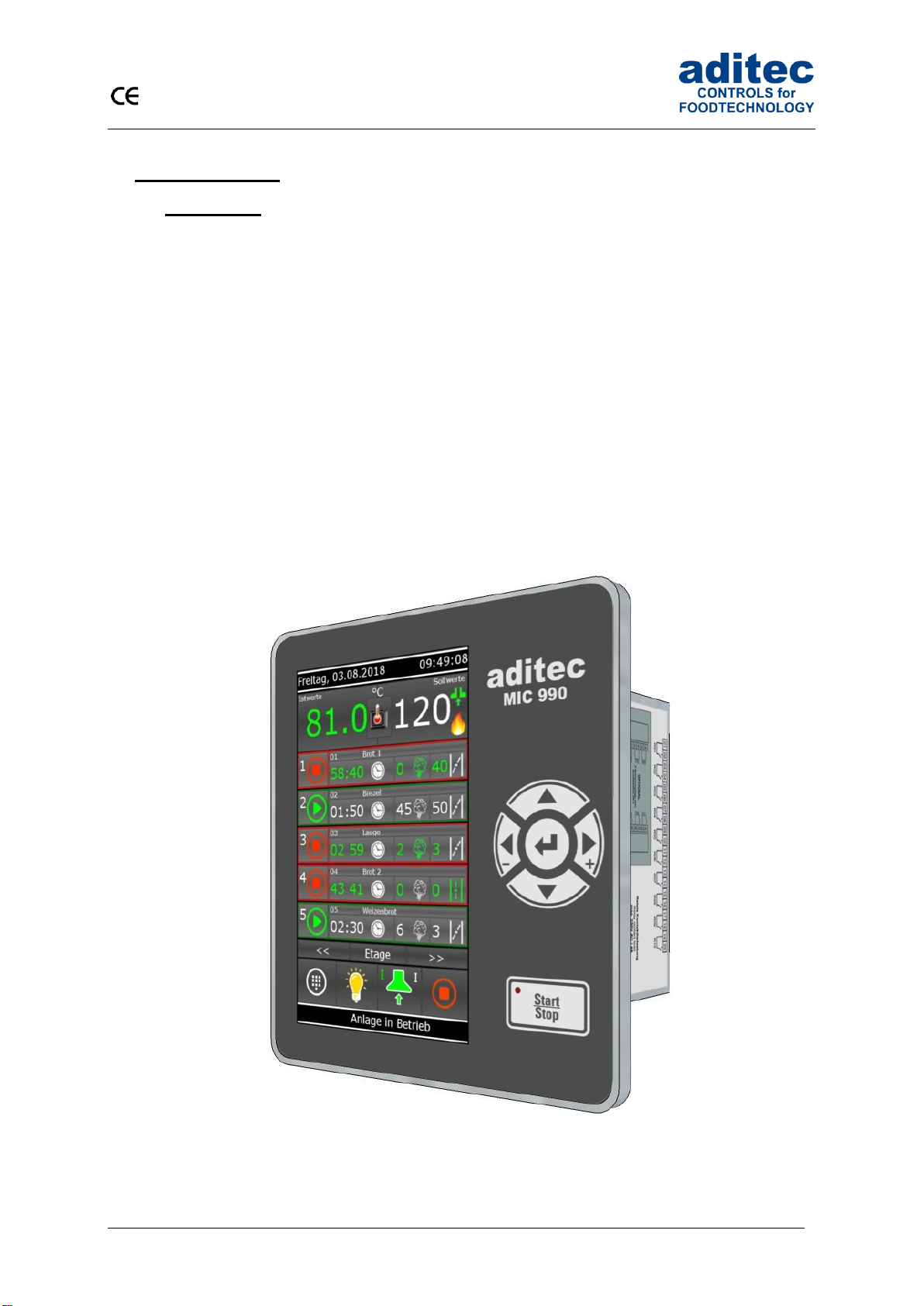
Processor MIC 990, with user-friendly touch panel, 7“ TFT display with resistive touch technology,
several interfaces and a housing of standard industrial quality, are designed for use in deck ovens.
In its standard version the controller is equipped with
4 Pt100 temperature inputs and
2 inputs which can be converted to Pt100 and current 4-20mA / voltage 0-10V or thermocouples
(compliant with DIN EN 60584).
The following interfaces allow communication: LAN/Ethernet and USB Serial Port.
In order to adapt the controller for specific purposes each control loop can be used as a 2-point
controller, XP controller or with PID behaviour.
MIC 990:
The standard version has 16 relay outputs
(12 normally open contact and 4 changeover contacts).
User Manual MIC 990
5
Issue 18.03.2021_00
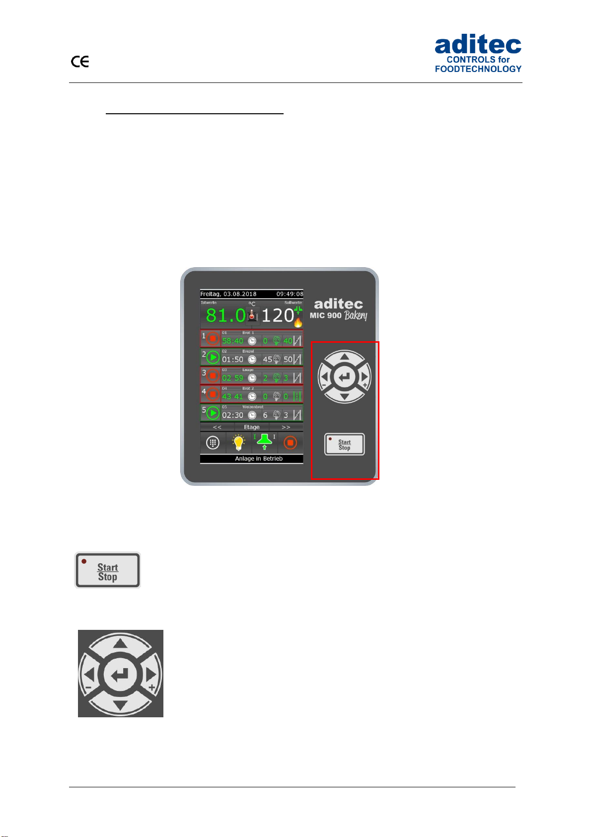
1.2 Display and operating area
The controller is sub-divided into an input/display panel and a control button panel.
1.2.1 Input and display touch panel
The upper half is a 7“ touch display. Here you can change the different settings and information on
program data and the input screens are shown.
1.2.2 Control buttons
The control buttons allow you to navigate through the operating elements with the help of the cursor
buttons. Use the “Cursor-Enter”button to confirm the entries you have made.
MIC 990
Start / Stop
Starting and stopping programs.
LED lights –control in operation
LED flashes –end of the program
Cursor left -
Moving horizontally to the next operating element on the
left.
Cursor right +
Moving horizontally to the next operating element on the
right.
Cursor up
Moving vertically up to the next operating element.
Entering number values (incremented).
Cursor down
Moving vertically down to the next operating element.
Entering number values (decremented).
Cursor ENTER
Confirm the selected button/box

User Manual MIC 990
6
Issue 18.03.2021_00
1.3 Functions of the on-screen key pad
Figure 1: Key pad
- Insert/replace mode
- Deleting individual symbols
- Deleting an entire text passage
- Capital /Lower case letters
- Numbers and special symbols
- Confirm entry
- Leaving the operation without changing the
original settings
- More special symbols

User Manual MIC 990
7
Issue 18.03.2021_00
1.4 Entering numerical values
A numerical pad is used to enter numerical values. It will be displayed when
you have to enter values.
- Deleting the value in an entry box
- Changing the leading sign of a value
- Closing the keypad. Changes made to the nominal value
are not saved.
- De-activating a nominal value
- Saving an entered value
Be aware
The controller also allows you to enter negative temperature values:
-In order to pre-program negative nominal values in a step, the installation manufacturer
has to pre-program negative nominal value limits for chamber and core.
- „0“ can be entered as a nominal value. The nominal value „Off“ is shown for chamber
and core when a new program step is pre-programmed. . This means: the nominal value
is deactivated. As soon as a value is entered (even if it is „0“) the nominal value counts
as activated. If you want to deactivate the nominal value later in the step, press
the „Off“ button.
1.4.1 Screen lock
All display functions are blocked when you press the „Enter“ button during 3 sec. On the lower margin
of the display appears “Lock”. To deactivate the look, press the “Enter” button for 5 sec.
Please not
The program processing is independent of screen lock. If the screen lock is activated in
operating mode the program will continue.
The activated screen lock has no influence on the communication with VisuNet or Service
program. If the screen lock is activated you can start and stop programs via VisuNet.
This function is helpful when the unit is cleaned up.
Figure 2:
Numerical pad
Eingabe
User Manual MIC 990
8
Issue 18.03.2021_00
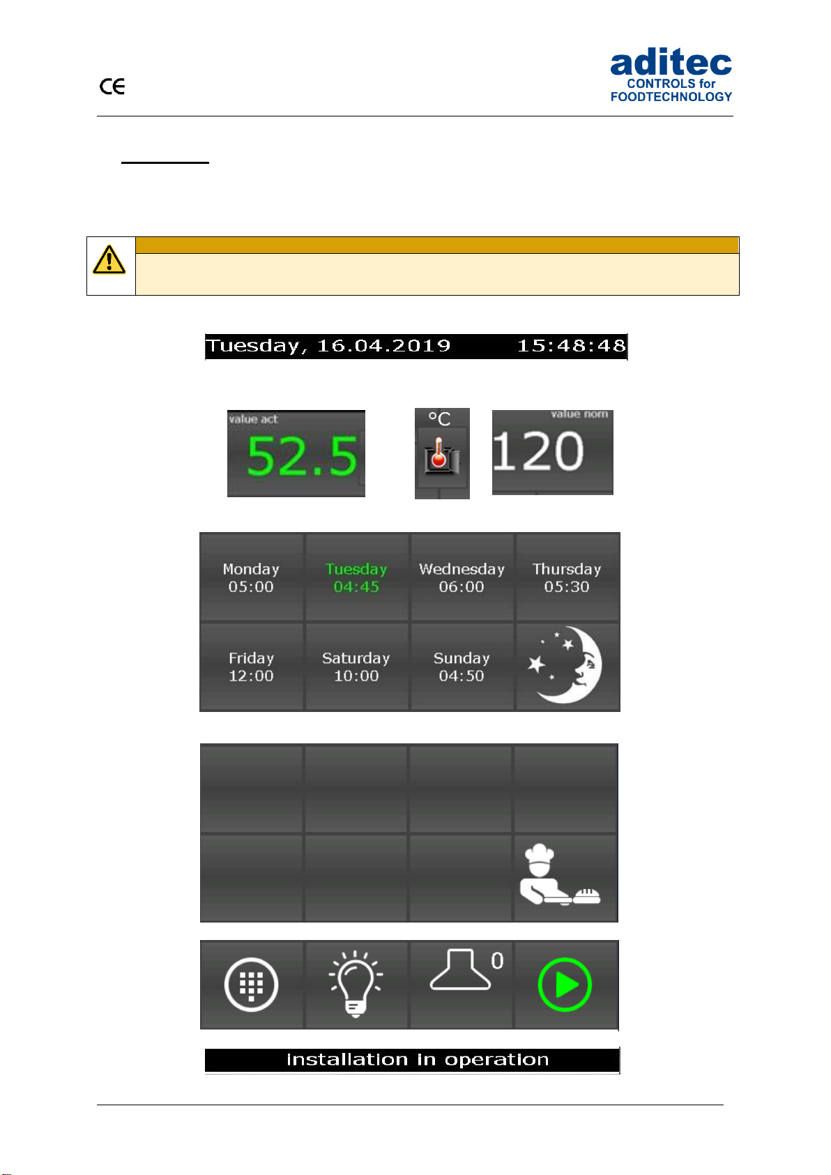
2 Standby
As soon as the controller has been connected to a power supply, it will automatically boot up and will
display the message „Loading please wait...“. This process can take up to 1 minute. Then you will get
to the standby screen.
Be aware
Please do not operate the touch screen with sharp implements i.e. pointed fingernails,
pens/pencils, screwdrivers etc. Only use blunt, soft implements i.e. fingers, rubber pens.
Date display
Actual value display
Unit
Nominal value
display
Day and time for nighttime preheating
Quick access and standby mode
Task bar
Status bar
User Manual MIC 990
9
Issue 18.03.2021_00
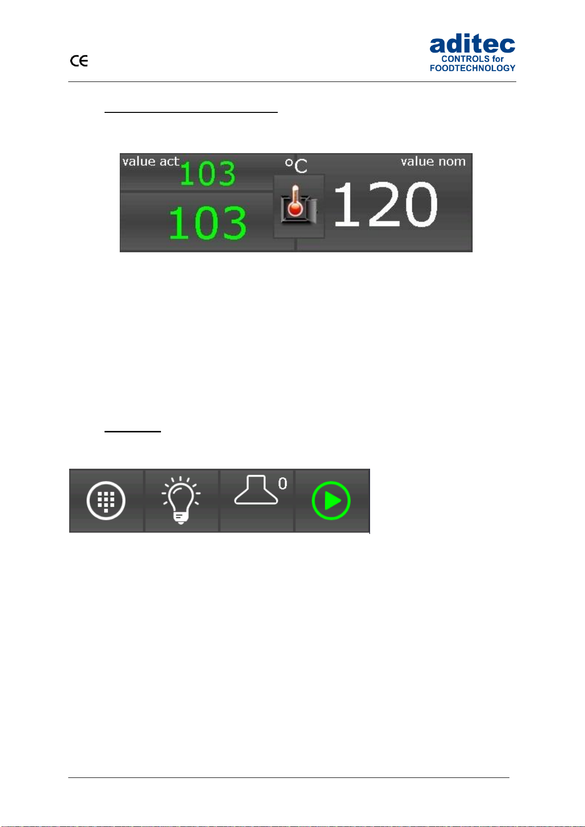
2.1 Actual and nominal values
Actual value:
Currently measured sensor value
Symbol/Scale (combined button):
Shows the measured variable and the measuring scale.
Nominal value:
Nominal values for preheating
2.2 Task bar
2.2.1 Start page / profiles
The task bar is sub-divided into 4 task buttons. If you leave the start page/standby by pressing a
button, you can get back to standby by pressing the „Start page“ button on any page you may be on.
Menu: Press the „Menu“ button to get to the menu page
(see „Menu page“, item 3, page 10)
Light: Here you can switch-on and switch-off the light in the oven
Exhaust air: switch-on and switch-of the exhaust air, quick tip you change between the level 1 and
level 2, off
Start: Standby: here you start the preheating mode immediately
Preheating: stops the preheating mode and changes in to the standby mode
Operating: stops the operating mode and changes in to the standby mode
Unit
Actual value
Nominal value
Symbol
Menu
Light
Exhaust air
Start

User Manual MIC 990
10
Issue 18.03.2021_00
2.3 Information bar
On the information bar you can see messages, operating status, alarm messages and the system
time.
3 Menu page
The „Menu“ page of the touch panel is arranged as follows:
▪Configuration:
System specific controller settings.
The settings are protected by a password and can only be set up by a service technician.
▪Service:
Settings for the maintenance personnel on-site: Initial start-up, maintenance work etc.
The settings are protected by a password and can only be set up by a service technician.
▪Profiles:
Settings for the operator/end user.
These settings are not password protected.
▪Programs:
Opens the program selection page.
▪Information:
Display of the information about the controller version and settings.
▪Start page:
Back to the start page/standby
User Manual MIC 990
11
Issue 18.03.2021_00
4 Programming mode
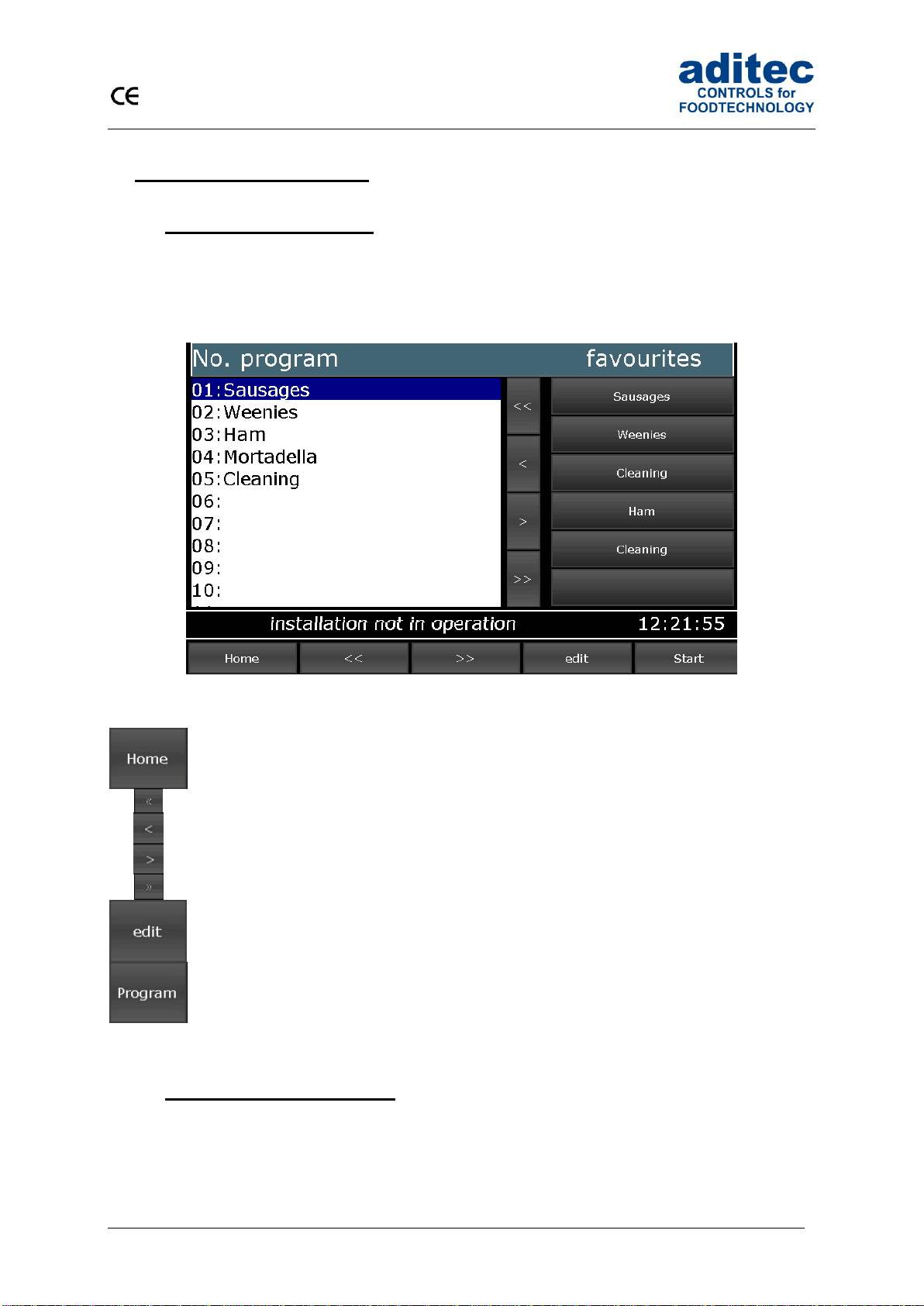
4.1 Selecting a program
To get to the „Program selection“ menu press the “Program” box
Press a program to select it. Use the arrow buttons to navigate within the display. Alternatively, you
can use the cursor button to navigation through the “program selection” list.
Figure 3: Program selection programming mode
Back to the start page/standby
Skipping backwards in the program list by blocks of 9 programs
Skipping to the previous program
Skipping to the next program
Skipping forwards in the program list by blocks of 9 programs
Editing, copying or deleting programs
Programing mode
4.2 Editing program steps
Start on the „Program selection“ display and highlight the program you want to edit by pressing on it.
Now press the „Program“ button on the task bar. Alternatively press the “Edit” button in the task bar. In
the next window press also the “Edit” button.

User Manual MIC 990
12
Issue 18.03.2021_00
4.2.1 Display for editing program steps
Program bar (note: program selection, copying programs, program pictures)
Step bar (note: process selection, copying steps )
Nominal values
Information bar (display: status)
Task bar (back, program back, program forward, menu, start)
Please note
Program and steps can also be added, copied or deleted on the „Edit” page. You can get to
the relevant sub-menu by pressing on the „Program“ or „Step“box, respectively.
See „Copying, deleting and adding programs/steps“, item4.2.4, page 13

User Manual MIC 990
13
Issue 18.03.2021_00
4.2.2 Entering nominal values
Press a nominal value box and a keypad will appear.
Enter the relevant value and confirm it by pressing
„Enter“.
Also see 1.3 Entering numerical values, page 7
4.2.3 Select program image
By touching the „Picture“ box appear separate
images. Please select your program image and
press „Enter“.
Hinweis
The program images located on the SD-card in the folder ProgImage. So they can easily be
exchanged. The pictures have a resolution of 90 x 64 pixel and have the JPG-format.
Creation of new images:
- Resolution of 90x64 (BxH) should not be exceeded.
- The image must have JPG-Format
- The image must have the following name:
Image_xxx.jpg (xxx = image number has to start with 001)
- Max. 999 images can be stored
4.2.4 Copying, deleting and adding programs/steps
Select the program you want to copy.

User Manual MIC 990
14
Issue 18.03.2021_00
Change to the „Program selection“display.
Press the “Edit” box on the task bar. A selection window will
open. Press „Copy“.
You can copy the selected program into another program.
Enter the relevant program number and confirm with „Enter“.
Be aware
A program is automatically copied when you press „Enter“.
The program that originally occupied that position is overwritten!
„Step number“ box
Double click the „Step number“ box and a menu window will open.
This allows you to add, copy or delete steps.
Adding
If you want to add e.g. a new 2. step, the pervious step 2 becomes
step 3 . This means all steps are moved backwards by one position.
Step 20 is deleted.
Copying
Copying a selected step into another program or into another position
within the same program.
Deleting
Deleting a selected step. All subsequent steps move forward by one
position.

User Manual MIC 990
15
Issue 18.03.2021_00
Be aware
A step is automatically copied when you press „Enter“.
The step that originally occupied that position is overwritten!
4.3 Setting up a program with VisuNet
VisuNet is a visualisation program for programming, automatic controlling, monitoring, logging,
backing-up, telecontrolling/telemonitoring of installations and processes.
4.3.1 Enabling VisuNet
When you want to set up or edit programs you need the COMFORT version of VisuNet. The controller
has to be enabled for this service. For further information contact your installation manufacturer or
aditec.
4.3.2 Editing programs with VisuNet
For how to edit programs with VisuNet please see the user manual „VisuNet Base / Comfort /
Premium“ – Chapter 5 „Entering, changing, copying and starting programs“.

User Manual MIC 990
16
Issue 18.03.2021_00
5 Nighttime preheating
In the standby mode you can prepare everything for nighttime preheating or you can start directly the
preheating.
Set the desired nominal value for the prehaeating.
Select the start date. Predefined start times can be
changed in Profil => Programming of start times.
For starting the preheating press the „Moon“ button.
Touch the day or time box and entert he desired start
time and start day. Confirm with “Enter” button.
Night mode active
-------------------------------------------------
If the start day and the start time are in the future begins
the waiting time.
The selected day and the “Moon” are colored blue.
In the information bar appears the time.
After this time limit is reached the controller changes
automatically in the preheating mode
With the „Start/Stop“ button you can cancel the start
process and return to the start page (standby).
Please note
During the waiting time is running the „Stop“ button flashes in the task bar. If you press the
button the waiting mode will be cancelled. The controller returns in standby mode.
Be aware
If administrators are actvated you must enter a password bevor the program starts.
Only operators with the right to start programs can do it.
User Manual MIC 990
17
Issue 18.03.2021_00
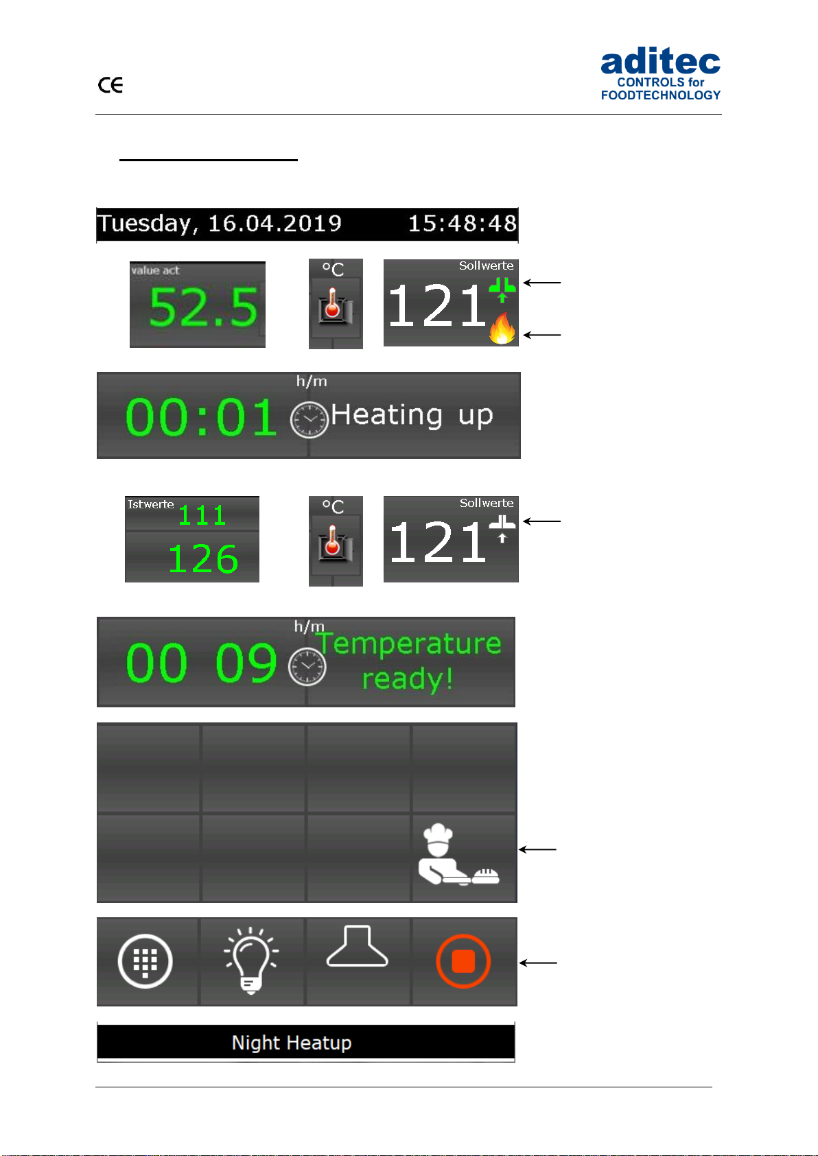
6 Preheating mode
Data display
Actual values
Units
Nominal values
Flap open, nominal
temperature below the
actual temperature
Burner active
Current preheating time Operating mode preheating
or
Actual values
Flap closed, nominal
temperature above/the
same as the actual
temperature
Current preheating time Operating mode
ready
Quick access and standby mode
Immediate change to the
standby mode
Task bar
With the „Start/Stop“
button you can cancel
the start process and
return to the start page
(standby).
Status bar
User Manual MIC 990
18
Issue 18.03.2021_00
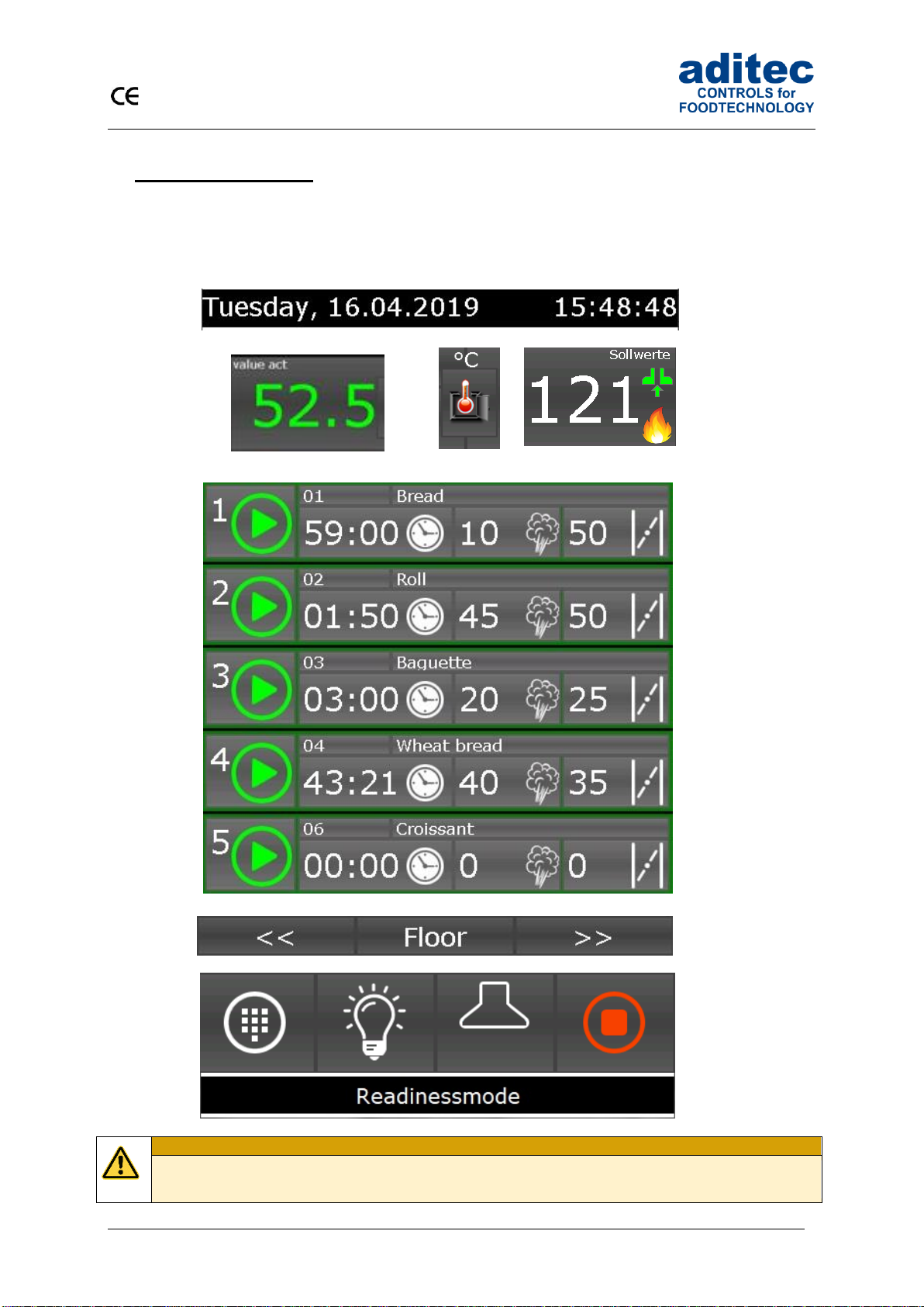
7 Stand by mode
The controller is running.
After program start the button „Stop“ will be highlighted in red. In the info bar appears the running text
„Standby mode“.
Data display
Actual values
Unit
Nominal values
Deck overview (1-5 decks)
Deck selection
Task bar
Be aware
If administrators are activated you must enter a password bevor the program starts.
Only operators with the right to start programs can do it.
User Manual MIC 990
19
Issue 18.03.2021_00
7.1 Separate deck
Program-
number
Program name
Deck number
Start button for
starting the
programs
Baking time
Steaming
time
Flap time
By pressing one of the boxes the controller changes over to deck
overview (see the separate dock overview)
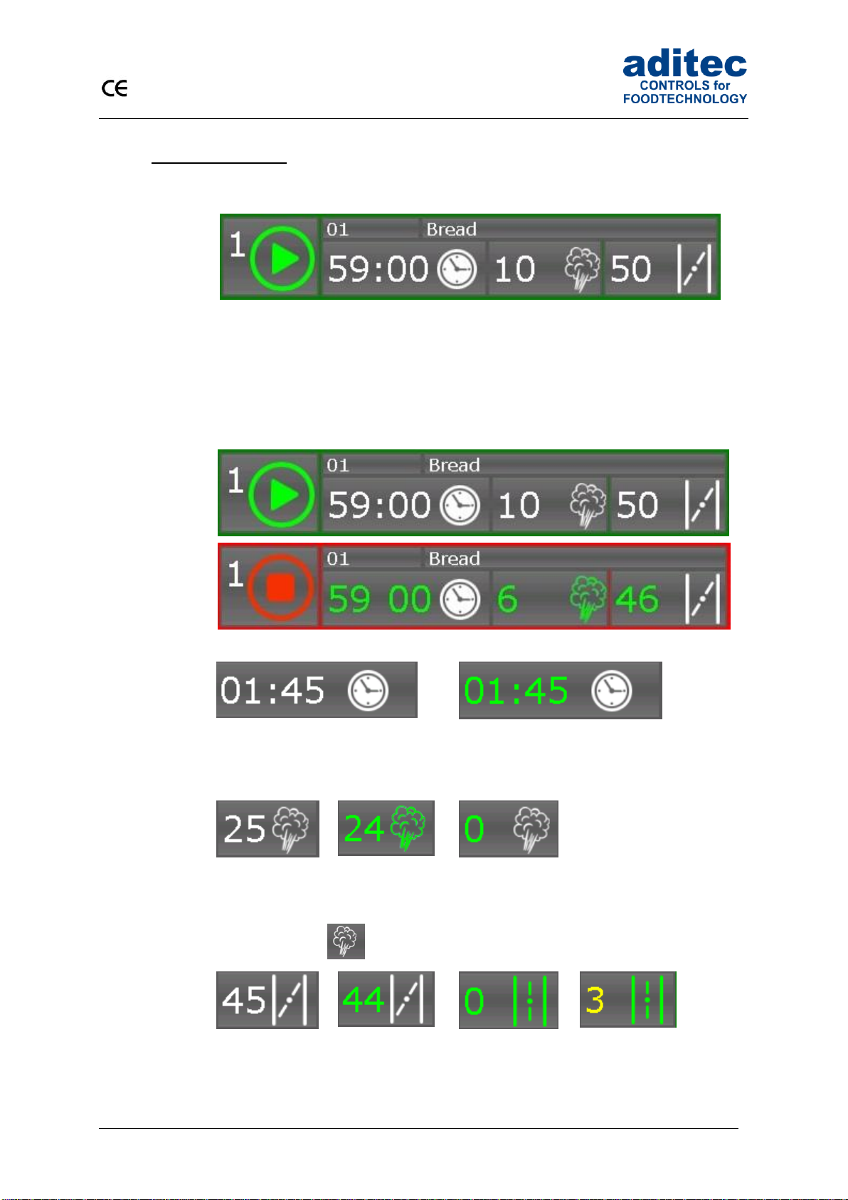
7.1.1 Status display
Program out of
operation
Programm in
operation
inactive
active
Baking time
Baking nom. time is displayed
Baking act. time is displayed
Colon flashes –step time is counted
Colon don’t flashes – step time is not counted
inactive
active
Steaming time
Steaming nom.
time
Steamin act. time
Steaming act.
time is expired
Recharge of steaming time in operation (from V90.03)
Press the button : Steam nuzzle is switched-on for the set time
inactive
active
Flap time
Steaming nom.
time is displayed
flap closed
Steaming act.
time is displayed
flap closed
Steaming act.
time is expired
flap open
Flap time on the end of
the program (can be set
by the service technician)
User Manual MIC 990
20
Issue 18.03.2021_00
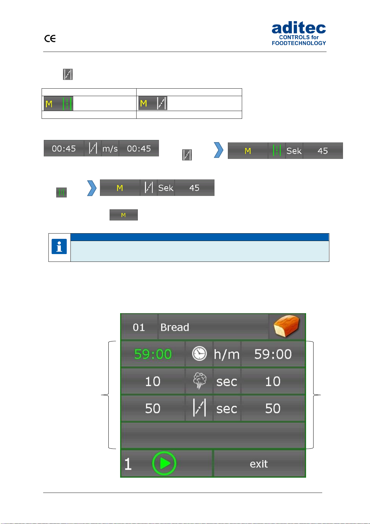
The exhaust flaps of each single floor can be switched on or off manually at any time by pressing the
button (from V90.03)
The flap is manually opened
The flap is manually closed
Status display: flap for each single floor
By pressing the button or if you enter a new nominal value you leave the manual mode.
Please note
The flap time keeps running independent from manual switching on/off.
7.1.2 Separate deck overview
Deck overview
Program number/
program name/
program image
Baking time
Steaming time
Flap time
Current deck
number
Program start/-stop
Leave the deck overview
Actual values
Nominal values
Press the
button
Press the
button
Flap is closed
Flap is open
Flap is closed
Table of contents


