Adleepower AP2G3-137 User manual

ADLEEPOWER
INSTRUCTION MANUAL
GENERAL-PURPOSE INVERTER
THANK YOU VERY MUCH FOR YOUR PURCHASE
OF ADLEE INVERTER APxG3 SERIES.
PLEASE READ THIS INSTRUCTION MANUAL
BEFORE INSTALLATION OF THE INVERTER.
R
AP2G3-137~AP2G3-1185
AP2G3-337~AP2G3-3220
AP4G3-337~AP4G3-3220

CONTENTS
1. RECEIVING
2. SPECIFICATIONS
3. DIMENSION DRAWINGS
4. INSTALLATION
5. DESCRIPTION OF TERMINALS
6. DIGITAL OPERATION PANEL
7. FUNCTIONS DESCRIPTION
8. PROTECTIVE FUNCTIION
9. PRECAUTIONS
10. TROUBLESHOOTING
11.APPLICATION
12. INVERTER SELECTION
13. APPENDIX
A. Optional braking resistor
B. Terminal wiring diagram
C. Remote operator
1
2
4
6
8
18
19
73
77
78
79
85
89
89
90
91

1. RECEIVING
Befor installation and wiring, check to see :
(1) No damage is found on each product after shipping.
(2) The product is as ordered (check the nameplate, voltage and fre-
quency).
(3) A set of inverter unit and instruction manual is contained in the
package.
For any irregularity, contact the sales shop where you purchased
immediately.
(4) Description of name plate
VER A 01
SOFTWARE
HARDWARE
VERSION
MODEL : AP 4 G3 - 3 37
Max Applicable motor(4 pole)
37 : 3.7KW 55 : 5.5KW 75 : 7.5KW
110 : 11KW 150 : 15KW 185 : 18.5KW
220 : 22KW
1: 1
3: 3
AP series
Voltage class :
2 : 200/220V
4 : 380/440V
IPM AC drive
1
∮
∮

2. SPECIFICATIONS
2
PROG
Model AP2G3
Voltage 1φ 220VAC ± 10% 3φ 220VAC ± 10%
Model No 137 155 175 1110 1150 1185 337 355 375 3110 3150 3185 3220
Input Frequency 50HZ/60HZ ±5%
Output Voltage 3φ 220VAC
Output Frequency 0.5 ~ 400HZ
Output
Rated current (A) 16 23 30 43 56 70 17 24 33 46 61 76 90
Capacity (KVA) 6.1 8.8 11.4 16.4 21.3 26.7 6.5 9.2 12.6 17.6 23.3 29 34
Largest motor
KW ( 2.4.6 poles ) 3.7 5.5 7.5 11 15 18.5 3.7 5.5 7.5 11 15 18.5 22
Control Sine wave pulse width modulation
Braking Regenerative discharge braking
Over current
Capacity 150% of rated current ( 1 minute)
Acceleration time 0.1 ~ 6000 SEC
Deceleration time 0.1 ~ 6000 SEC
Frequency
setting Digital Use keyboard for setting and confirm by
Analog Analog signal input DC 0~5V, 0~10V, 4~20mA
Output signal Open collector output 50v 50mA Max
Cooling Method Air-cooled
Dimension drawing Fig 1 Fig 2 Fig 1 Fig 2
Weight ( KG ) 5.5 6.2 6.6 17 18 18.5 5.5 6.2 6.6 17 18 18.5 19

PROG
3
Model AP4G3
Voltage 3φ 380/440VAC ±10%
Model No 337 355 375 3110 3150 3185 3220
Input Frequency 50HZ/60HZ ±5%
Output Voltage 3φ 380/440VAC
Output Frequency 0.5 ~ 400HZ
Output
Rated current (A) 8.5 12 16.5 23 31 38 45
Capacity (KVA) 6.5 9.2 12.6 17.6 23.6 29 34
Largest motor
KW ( 2.4.6 poles ) 3.7 5.5 7.5 11 15 18.5 22
Control Sine wave pulse width modulation
Braking Regenerative discharge braking
Over current
Capacity 150% of rated current ( 1 minute)
Acceleration time 0.1 ~ 6000 SEC
Deceleration time 0.1 ~ 6000 SEC
Frequency
setting Digital Use keyboard for setting and confirm by
Analog Analog signal input DC 0~5V, 0~10V, 4~20mA
Output signal Open collector output 50v 50mA Max
Cooling Method Air-cooled
Dimension drawing Fig 1 Fig 2
Weight ( KG ) 5.5 6.2 6.6 6.8 18 18.5 19.5

3. DIMENSION DRAWINGS
( AP2G3-137 AP2G3-155 AP2G3-175 )
( AP2G3-337 AP2G3-355 AP2G3-375 )
( AP4G3-337 AP4G3-355 AP4G3-375 AP4G3-3110 )
Fig 1
Unit : mm
4

Fig 2
Unit : mm
5
( AP2G3-1110 AP2G3-1150 AP2G3-1185 )
( AP2G3-3110 AP2G3-3150 AP2G3-3185 AP2G3-3220 )
( AP4G3-3150 AP4G3-3185 AP4G3-3220 )
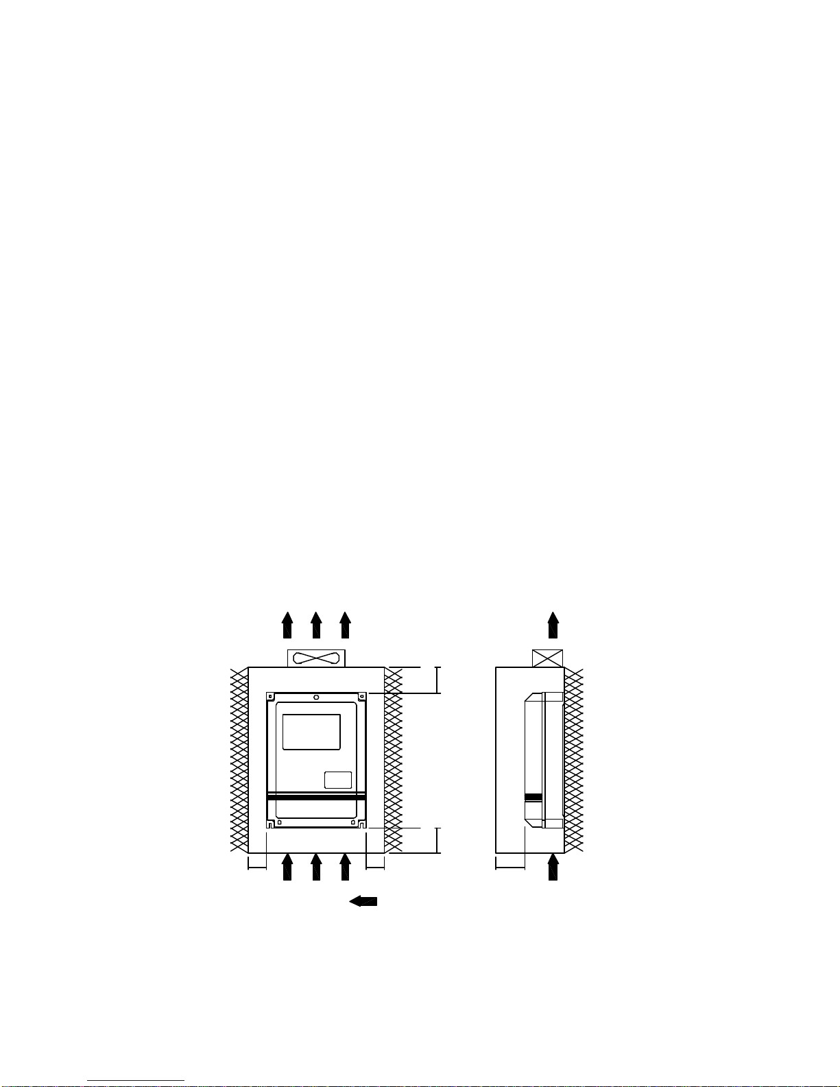
4. INSTALLATION
Inadequate environment around installation site and installation
surface can result in damage to the inverter.
Before operating the APxG3 series inverter, please check the following
points :
(1) Avoid high temperature, high humidity, easy-to-dew ambient envi-
ronment. Don’t expose to dust or dirt, corrosive gas, and coolant
mist, and direct sunlight. Place the unit in a well-ventilated room.
(2) Avoid a place subjected to substantial vibration.
(3) When installing the unit within the cabinet. Please pay attention to
ventilation and limit the ambient temperature in between -10℃~
45℃. (14℉~ 113℉).
(4) Use a nonflammable material, such a steel sheet on the wall for
installation. (The rear side will generate heat)
(5) Install the unit always vertically with a marginal spacing around.
6
AIR FLOW
15 cm
15 cm
5 cm
10 cm
10 cm

7
AIR FLOW
5. DESCRIPTION OF TERMINALS
(1) Main circuit connection diagram
8
RSTP2 P1 U V W
IM
Ground Power source Braking resistor
(★Note)
Ground
AP2G3-137~175
AP2G3-337~375
AP4G3-337~3110
AP2G3-1110~1185
AP2G3-3110~3220
AP4G3-3150~3220
Note : Release the internal braking resistor when connect external brak-
ing resistor.
Main circuit terminal
Symbol Terminal name Description
R / L1
Inverter power source
Terminal connecting with
power source
Single phase input : L1/R,
L2/S
S / L2
T / L3
U
Inverter output terminal Terminal connecting with
motor
V
W
P / P1 DC voltage terminal Regenerative braking resistor
connecting terminal
PR / P2
RSTU V WPPR
IM
Ground Powersource Braking resistor
(★Note)
Ground

(2) Description of hardware setting
AP2G3-137~AP2G3-175, AP2G3-337~AP2G3-375,
AP4G3-337~AP4G3-3110
AP2G3-1110~AP2G3-1185, AP2G3-3110~AP2G3-3220,
AP4G3-3150~AP4G3-3220
GND FA1 FA2 HCOMFWD REV CF1 CF2 FT1 FT2 RST ARR/RUN MET -
JP3
MB+MA AMC BC
RS485
SW1
1 32 4
10VFG1
JP1
J3
JP2
10V GND FA1 FA2 FG1 HCOMFWD REV CF1 CF2 FT1 FT2 RST ARR/RUN
SW1
1 2 3 4
JP1
MBMET MA AMC BCJ4
RS485 5 6
JP2
9
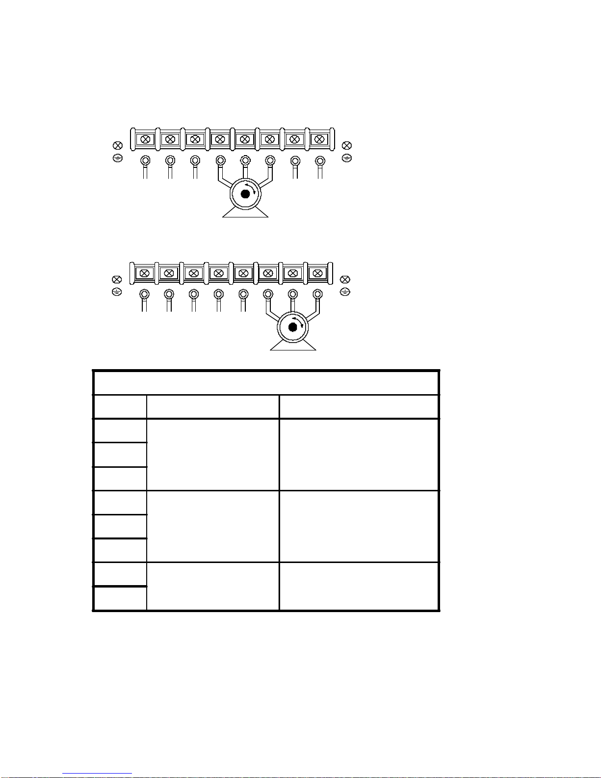
(3) Analog signal switch setting
AP2G3-137~175, AP2G3-337~375, AP4G3-337~3110
ON
1 2 3 4
ON
1 2 3 4
SIGNAL FA1 FA2
0 - 10V
0 - 5V
4 - 20mA
(Note1)★
Error setting
ON
1 2 3 4
ON
1 2 3 4
ON
1 2 3 4
ON
1 2 3 4
ON
1 2 3 4
ON
1 2 3 4
10
11
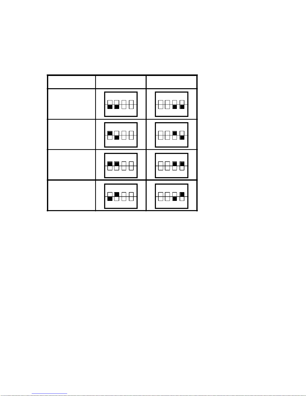
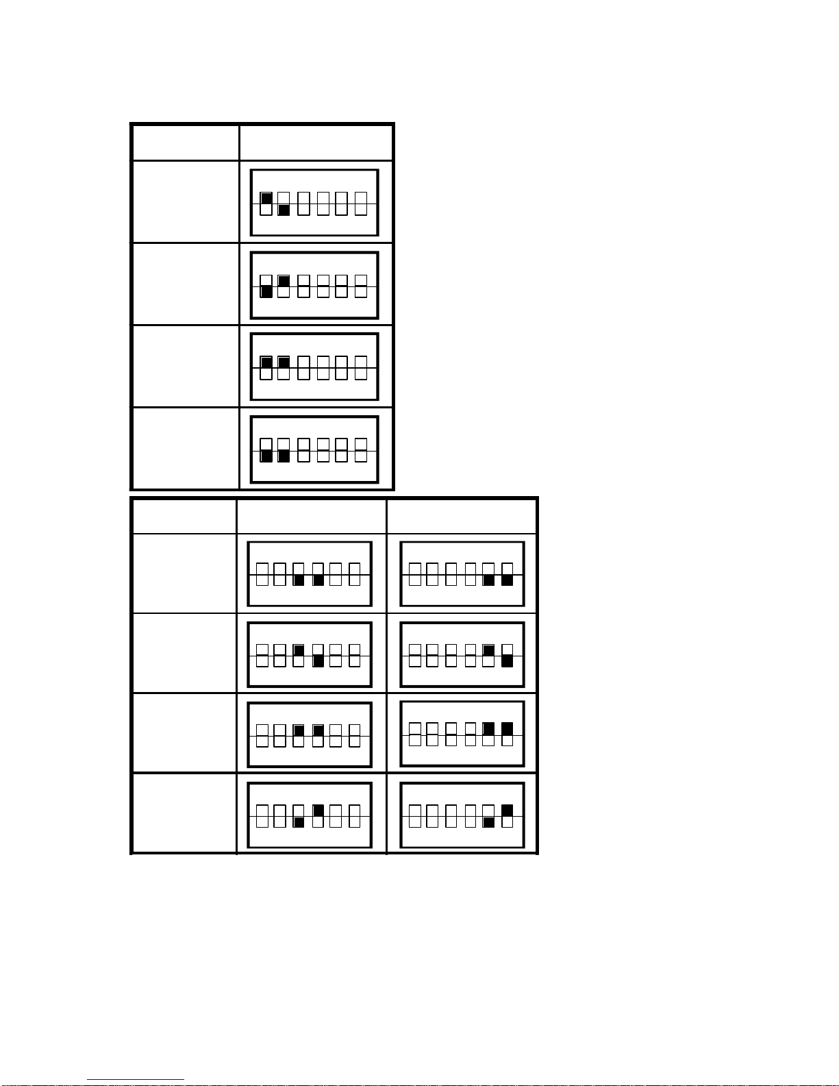
AP2G3-1110~1185, AP2G3-3110~3220, AP4G3-3150~3220
SIGNAL Keypad VR/F306
Keypad VR
F306
Error setting
Error setting
ON
1 2 3 4 5 6
ON
1 2 3 4 5 6
ON
1 2 3 4 5 6
ON
1 2 3 4 5 6
Note 1 : Input 4-20mA at FA1 or FA2, refer to function CD10/CD12/
CD44/CD45/CD54.
SIGNAL FA1 FA2
0 - 10V
0 - 5V
4 - 20mA
(Note1)★
Error setting
ON
1 2 3 4 5 6
ON
1 2 3 4 5 6
ON
1 2 3 4 5 6
ON
1 2 3 4 5 6
ON
1 2 3 4 5 6
ON
1 2 3 4 5 6
ON
1 2 3 4 5 6
ON
1 2 3 4 5 6

(4) Jumper setting
1. JP1 : FT2 over temperature selection
2. JP2 : MET output selection
3. JP3 : Pannel VR and F306 VR selection
AP2G3-137~AP2G3-175, AP2G3-337~AP2G3-375,
AP4G3-337~AP4G3-3110
4. J3 : RUN/ARR Relay selection
AP2G3-137~AP2G3-175, AP2G3-337~AP2G3-375,
AP4G3-337~AP4G3-3110
5. J4 : RUN/ARR Relay selection
AP2G3-1110~AP2G3-1185, AP2G3-3110~AP2G3-3220,
AP4G3-3150~AP4G3-3220
Note : When J3 or J4 select ARR, ARR/RUN terminal is RUN open
collector output and MA/MB/MC Relay is ARR.
When J3 or J4 select RUN, ARR/RUN terminal is ARR open
collector output and MA/MB/MC Relay is RUN.
12
1 and 2 short circuit : PTC temperature switch.
2 and 3 short circuit : NTC temperature switch.
1
2
3
1 and 2 short circuit : Pannel VR.
2 and 3 short circuit : F306 VR.
1
2
3
Left : ARR Relay.
Right : RUN Relay.
Up : RUN Relay.
Down : ARR Relay.
1 and 2 short circuit : Connect to meter.
2 and 3 short circuit : Analog output.
(0~10VDC refer to 0~CD14)
1
2
3

13
(5) Control circuit terminal
AP2G3-137~175、AP2G3-337~375、AP4G3-337~3110
AP2G3-1110~1185、AP2G3-3110~3220、AP4G3-3150~3220
10V GND FA1 FA2 FG1 HCOM REV CF1 CF2 FT1 FT2 RST ARR/RUN MET MA MB MC A
16321 10654 987 131211 1514 191817 20
B
21
C
22
FWD
HZ
Contact rating :
ARR/RUN 1A 240VAC
Relay Fault Relay
VR5KB Ground
1A 30VDC
FG1 10V GND FA1 FA2 HCOMFWDREV CF1 CF2 FT1 FT2 RSTARR/RUN MET -+MA MB
VR5KB
Fault Relay
Contact rating :
1A 30VDC
HZ
BAMC C
ARR/RUN
RelayFANGround
1A 240VAC

CF1 CF2 SPEED
OFF OFF SPEED - 1
ON OFF SPEED - 2
OFF ON SPEED - 3
ON ON SPEED - 4
14
Symbol Control circuit terminal
Terminal Description
FG1 Ground terminal 1 Grounding
10V Analog source Power source +10V of analog terminals
GND Analog common terminal Common terminal of free analog terminals
FA1 Free analog terminal 1 See functions description (CD44)
FA2 Free analog terminal 2 See functions description (CD45)
HRef. voltage Basic source (+10V) terminal for frequency
COM Common terminal Common terminal of control board
FWD Forward operation Forward operation / stop terminal
REV Reverse operation Reverse operation / stop terminal
CF1
Multistage speed terminal
CF2
FT1 Multi function terminal 1 See functions description (CD42)
FT2 Multi function terminal 2 See functions description (CD43)
RST Reset Reset
RUN
ARR Operation output terminal
Frequency arrival signal Open collector output 50Vdc 50mA Max.
MET Frequency meter terminal 0~100% duty open collector output or
0~10VDC output (0~CD14)
AAlarm output A Fault alarm contact (normal open)
CAlarm output C Fault alarm contact (common)
BAlarm output B Fault alarm contact (normal close)
MA
Relay output RUN/ARR
Relay output contact (normal open)
MB Relay output contact (normal close)
MC Relay output contact (common)

L1/R
L2/S
U
V
W
APxG3-Series
IM
THRY
E
POWER SOURCE
L3/T
(6) WIRING
6-1 Wiring of main circuit
1.AP2G3 1 power source
terminal connect L1/R and L2/S.
2.AP2G3 3 and AP4G3 3
power source terminal connect
L1/R, L2/S and L3/T.
6-2 Wiring equipments
Select the wiring equipment and wiring size, refer to the table
below.
1. On the input power side, a molded case circuit breaker (MCCB)
to protect inverter primary wiring should be installed.
2. A leakage current breaker threshold of 200mA and above, or of
inverter use is recommended.
3. Use of input side magnetic contactor. An input MC can be used to
prevent an automatic restart after recovery from an external power
loss during remote control operation. However, do not use the MC
frequently for start/stop operation, or will lead to a reduced reliabil-
ity.
4. In general, magnetic contactors on the output of the inverter,
Should not be used for motor control. Starting a motor with the
inverter running will cause large surge currents and the inverter
overcurrent protector to trigger.
15
Model AP2G3 AP4G3
Model No 137 155 175 1110 1150 1185 337 355 375 3110 3150 3185 3220 337 355 375 3110 3150 3185 3220
Capacity (KVA) 6.1 8.8 11.4 16.4 21.3 26.7 6.5 9.2 12.6 17.6 23.3 29 34 6.5 9.2 12.6 17.6 23.6 29 34
Current (A) 16 23 30 43 56 70 17 24 33 46 61 76 90 9 12 17 23 31 38 45
Circuit Breaker
(MCCB) (A) 20 30 50 75 100 125 20 30 50 75 100 125 150 15 20 30 50 50 75 75
Electro-Magnetic
Contactor (A) 18 35 50 65 80 93 18 35 50 65 80 93 93 12 18 18 35 48 50 50
Thermal relay
RC value (A) 15 20 28 40 55 67 15 20 28 40 55 67 80 6.8 915 20 28 40 40
∮
∮
∮

6-3 Surge absorber
In order to prevent malfunction, provide the surge absorber on the
coils of the electromagnetic contactors, relays and other devices
which are to be used adjacent of the inverter.
6-4 Cable size and length
If the inverter is connected to a distant motor (especially when low
frequency is output), motor torque decreases because of voltage
drop in the cable. Use sufficiently heavy wire.
Changing the carrier frequency reduce RF1 noise and leakage
current. (Refere to the table below)
16
Distance
INVERTER →MOTOR under
25M under
50M under
100M above
100M
APxG3 SERIES under
16KHZ under
10KHZ under
5KHZ under
2.5KHZ

(a) (b) (c)
17
6-5 Wiring and cautionary points
A. Main circuit
1. Don’t connect the cables of the power supply side (L1/R,L2/S,L3/
T) to the U, V and W output terminals for the motor.
2. Don’t connect any electromagnetic contactor between the
inverter and motor. If it is inevitable, turn on the contactor when
both the inverter and motor are both at stand still.
3. Don’t put the advance phase capacitor between the inverter and
motor.
4. Put MCCB in the input power supply.
B. Control signal circuit
1. Separate the power cables of main circuit etc. from the control
cables of the sequence and analog signals by passing the cables
through the different ducts.
2. Use twisted pair shielded wire for control signal and connect the
shield to earth terminal at on end, COMMON terminal of
control board. Leave the other end of shielding open.
3. Avoid common Ground leads between high and low level
voltage equipment.
C. Grounding
1. Be sure ground both the inverter and motor.
2. Keep grounded leads as short as possible.
3. Shield cables used to protect low-level signal leads should
grounded at one end point.
4. Provide class 3 grounding (100Ωor less) for a terminal.
5. When grounding several inverters, make connections as shown
below, no loop is produced as shown in FIG “a “, FIG “b“.

6. DIGITAL OPERATION PANEL
Operation key Key function Description
FWD RUN Forward run Commands forward run
REV RUN Reverse run Commands reverse run
SHIFT Cursor
movement Select the digit
DOWN Down Decrease the parameter value
UP Up Increase the parameter value
PROG Memory
storage Saves the setting vaule
FUNC Function Press once to select function CDxx and
press again to change its content
STOP Stop Stop operation / Escape to standby mode
18
PROG
FUNC
STOP
FWD FREQ. SET
REV
AP G3DSP
Model
Indication
VR
Key
LED Operating
Indication
AP-G3 DSP
SMART INVERTER
PROG STOP
FUNC
FWDREV
Indication
Model
Key
Digital
Indication
Indication
LED Operating
Other manuals for AP2G3-137
1
This manual suits for next models
5
Table of contents
Other Adleepower Inverter manuals


