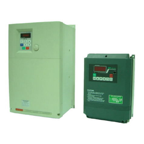
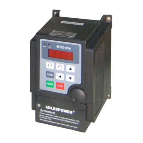
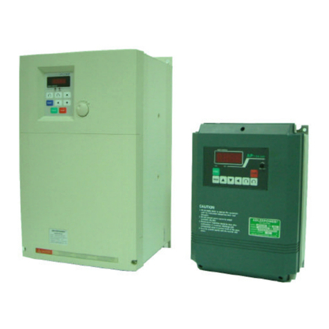
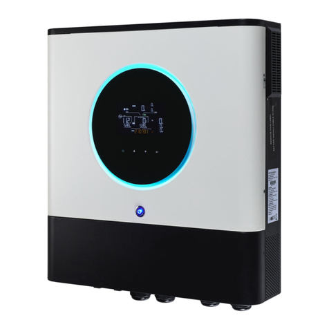
Adleepower AP2G5-37 User manual

ADLEEPOWER
INSTRUCTION MANUAL
VARITORQUE INVERTER
THANK YOU VERY MUCH FOR YOUR PURCHASE
OF ADLEE INVERTER APxG5 SERIES.
PLEASE READ THIS INSTRUCTION MANUAL
BEFORE INSTALL THE INVERTER.
R

CONTENTS
1. PREFACE
1-1. Acceptance inspection and precautions
1-2. Nameplate of rating details
2. SPECIFICATIONS
3. DIMENSION
4. EXTERNAL VIEW AND COMPONENT NAMES
4-1. Parts
4-2. Keypad explication
5. INSTALLATION
5-1. Installation environment
5-2. Installation
6. DESCRIPTION OF TERMINALS AND WIRING
6-1. Wiring diagram
6-2. Main circuit connection diagram and wiring
6-3. Connection of external control signals
6-4. Analog signal DIP switch setting
6-5. Main circuit’s breaker and magnetic contactor for wiring
6-6. Surge absorber
6-7. Cable size and length
6-8. Cautionary points for wiring
7. OPERATION TEST
7-1. Pre-check points
○○○○○○○○○○○○○○○○○○○○○○○○○○
○○○○○○○○○○○○○○○○○○○○○○○○○○○○○○
○○○○○○○○○○○○○○○○○○○○○○○○○○○○○○○○○○
○○○○○○○○○○○○○○○○○○○○○○
○○○○○○○○○○○○○○○○○○
○○○○○○○○○○○○○○○○○○○○○○○○○○○○○○○○○○
○○ ○○○○○○○○○○○○○
○○○○○
○○○○○○○○○○○○○○○○○○○○○○○○○○○○○○○○○○○○○
○○○○○○○○○○○○○○○○○○○○○○○○○○○○○○○○○○○○○○○
○○○○○○○○○○○○○○○○○○○○○○○○○○○○○○○○○○○
○○○○○○○○○○○○○○○○○○○○○○○○○○○○○○○○○○○○○○○○○
○○○○○○○○○○○○○○○○○○○○○○○○○○○○○○○
○○○○○○○○○○○○○○○○○○○○○○○○○
○○○○○○○○○○○○○
○○○○○○○○○○○○○○○○○○○○○○○○○○○○
○○○○○○○○○○○○○○○○○○○○○○○○○○○○○○○○○○○○○○
○○○○○○○○○○○○○○
○○○○○○○○○○○○○○○○
○○○○○○○○○○○○○○○○○○○○○○○○○○○○○○○○○○○○○○○○
1
3
4
5
6
8
8
10
11
11
11
12
12
13
14
14
16
16
16
17
19
19
○○○○○○○○○○○○○○○○○○○○○○○○○○○○○○○○○○○
○○ ○○○○○○○○○○○○○○○○○○○○○○○○○○○○○○○○

CONTENTS
7-2. Cautions for operating test
7-3. Setting for operation test
8. CONTROL MODE SETTING
8-1. Control mode selection
8-2. Control mode characteristics
8-3. Control mode change
8-4. Motor parameter Auto Tuning procedure
9. PARAMETER EXPLANATIONS
9-1. Parameters lists
9-2. Functional parameters
9-3. Parameter descriptions
10. MAINTENANCE AND FAILURES ELIMINATE
10-1. Attention points of maintenance and inspection
10-2. Regular checking items
10-3. Trouble shooting
11. APPLICATION
Appendix 1 Select right inverter
Appendix 2 Inverter capacity calculation formula
Appendix 3 Motor selection reminder
Appendix 4 Remote operator F306
Appendix 5 Optional braking resistor
Appendix 6 Version
19
20
24
24
25
26
26
29
29
38
44
75
75
75
76
79
85
87
89
90
91
92
○○○○○○○○○○○○○○○○○○○○○○○○○○○○○○○○○○○○
○○○○○○○○○○○○○○○○○○○○○○○○○○○○
○○○○○○○○○○○○○○○○○○○○○○○○
○○○○○○○○○○○○○○○○○○○○○○○○○
○○○○○○○○○○○○○○
○○○○○○○○○○○○○○○○○○○○○○○○○○○○○○○○○○○○
○○○○○○○○○○○○○○○○○○○○○○○○○○○○○○○○
○○○○○○○○○○○○○○○○○○○○○○○○
○○ ○○○○○○○○○○○○○○○○○○○○○○○○
○○ ○○○○○○○
○○○○○○○○○○○○○
○○○○○○○○○○○○○○○○○○○○○○○○○○○○
○○○○○○○○○○○○○○○○○○○○○○○○○○○○○○○○○
○○○○○○○○○○○○○○○○○○○○○○○○
○○○○○○○○○○○○○○○○○○○○○○○○○○○○
○○○○○○○○○○○○○○○○○○○○○○○
○○○○○○○○○○○○○○○○○○○○○○○○○○○○○
○○○○○○○○○○○○○○○
○○ ○○○○○○○○○○○○○○○○○○○○○○○○○
○○○○○○○○○○○○○○○○○○○○○○○○○○
○○○○○○○○○○○○○○○○○○○○○○○○○○○
○○ ○○○○○○○○○○○○○○○○○○○○○○○○

!
1. PREFACE
Thank you for purchasing ADLEEPOWER Varitorque Inverter
APXG5 . Please read this manual thoroughly before install and
operate APXG5 .
This manual should be stored by the user of the APXG5 for ref-
erence of maintenance and inspection.
Indicated a potentially hazardous situation which,
if not avoided, could result in death or serious
personnel injury.
Indicates a potentially hazardous situation which,
if not avoided, may result in minor or moderate
personnel injury and damage to equipment.
1
!
Ω
!
Danger
!
Caution
!
regnaD
denrutsiylppusrewopehttahtgniyfirevretfagniriwecnemmocylnO
.FFO
.lennosrepdeifilauqybylnodemrofrepebdluohsgniriW
oterusekaMtcennocecnatsiserdnuorG.lanimretdnuorgeht1.0
.sselro
oteruliaF.noitarepognirudlangistnemeleynaerusaemtonoD
.yrujnilanosrepnitlusernacnoituacsihtevresbo
ehttahtgniyfirevretfaylnonoitcepsniroecnanetniammrofreP
siecruosrewoptiucricniamehtretfadnaFFOseogDELEGRAHC
.FFOdenrut
nitlusernacgninrawsihtevresbooteruliaF.tcudorpehtyfidomreveN
.eetnaraugehtetadilavnilliwdnayrujnilanosreprokcohslacirtcelena
noituaC
)latem.e.i(.lairetamelbammalfnonnoretrevniehttnuoM
gniloocrehtoronafallatsni,erusolcnenanistinugnitnuomnehW
.54woleberutarepmetriaekatniehtpeekotecived
.tinuehtotegamadroerifaesuacyamgnitaehrevO
℃

2
UVW
power input
!
±
※
noituaC
.egatlovdetartupniretrevniotegatlovecruosrewopmrifnocesaelP
gnikarbasddaretrevninehwtcerrocsigniriwehterusekamesaelP
.retsiser
dnaretrevniehtneewtebroticapacesahpecnavdaehttuptonoD
.rotom
dnaretrevniehthtobdnuorgeruseB.slobmysgnidnuorgsi
.rotom
.retrevnifolanimretehtnodekcolsiretcennocrewopehtkcehC
revodnadezidixoeblliwretcennoc,esiwrehto,ssenesooltonoD(
).taeh
ro%01caV022siegatlovecruosrewoptupniehttahtkcehC
.%01caV044/083
ehtdna)slanimrettupni(T,S,RotecruosrewopehttcennocoteruseB
ehtegamadlliwnoitcennocgnorW(.)slanimrettuptuo(.W.V.Uotrotom
).retrevni
eraselbuortnehwstrapcinortceleroftnemecalperynaekamtonoD
.derrucco
esuacyamtI.retrevniehtfotsetegatlovdnatshtiwamrofreptonoD
.egamadebotsehctiwsrewoprostraprotcudnocimes
gnitareporofretrevnidnaecruosrewopneewtebyalerllatsnitonoD
.potsdnatrats
±
Motor

3
1-1 Acceptance Inspection and Precautions
During product manufacturing, packaging, and shipment have
been standardised. If any problems are discovered, please
contact your dealer or producer immediately.
. Any damage with each product after shipping.
. The instruction manual is contained in the package.
. The product as same as an order (check the nameplate,
voltage and frequency).
. All of terminals are locked and unusual substance.
. The keyboard of remote control must be corrected.
. Check the additional accessories.
!
noituaC
lanimretrodapyekesudluohs"pots"dna"trats"rotomgnitareporoF
.snoitcnufesehtlortnocot
rotomdnaretrevnineewtebroticapacgnicnavdaesahpllatsnitonoD
.rotomgnitareporof
ON - OFF
(NFB)
power
source

1-2 Nameplate of rating details
4
VER V 01
SOFTWARE
HARDWARE
VERSION
ADLEEPOWER R
MODEL AP2G5-110 VER V01
CAPACITY 17.6KVA (11KW/15HP)
OUTPUT CURRENT 46A
INPUT AC3 200/220V 50/60 Hz
FUSE AMP 75A
MODEL : AP 2 G5 - 110 R
Remote control
Max Applicable motor
(4 poles)
37 : 3.7KW
55 : 5.5KW
75 : 7.5KW
110 : 11KW
150 : 15KW
185 : 18.5KW
220 : 22KW
AP series
Voltage class : 2 200/220V
4 380/440V
Varitorque Inverter
MODEL
SOURCE
CAPACITY
AC3 380/440/460V
VARITORGUE INVERTER
6.5KVA(3.7KW/5HP)
AP4G5-337
HZ
VER V01
50/60
R
FUSE AMP A
15
OUTPUT CURRENT 9A

5
2. SPECIFICATION
ψ
ψ
ψ
ψ
±
±
±
ledoM5G2PA5G4PA
egatloV%01V0223%01V044/0833
oNledoM735557011051581022735557011051581022
ycneuqerFtupnI%5ZH06/05
egatloVtuptuOV0223V044~V0833
ycneuqerFtuptuOZH004~ZH5.0
detaRtupruO
)A(tnerruc 714233641667095.8215.6132138324
)AVK(yticapaC5.62.96.216.713.3292435.62.96.215.716.32928.23
rotometairporppA
)WK( 7.35.55.711515.81227.35.55.711515.8122
lortnoCMWPVS
gnikarB gnikarbegrahcsidevitarenegeR
yticapactnerruC )etunimeno(tnerrucdetarfo%051
emitnoitareleccAceS0021~2.0
emitnoitareleceDceS0021~2.0
ycneuqerF
gnitteS
latigiD ybmrifnocdnagnittesrofdraobyekesU
golanA langisgolanaAm02~4,CDV01~0,CDV5~0
epytyalpsiD )lanimret(langisgolanaroyalpsidlatigiD
noisnemiD1giF2giF1giF2giF
dohteMgnilloCdelooc-riA
)GKWN(thgieW6.58.52.65.415.4161616.58.52.62.65.412.5161

Unit : mm
3. DIMENSION
Fig 1
6

Unit : mm
7
Fig 2
1.Do not connect powers ourceto
ou t p u t te r min als. ( U .V .W. )
2.Do not merger between poles.
afterc onfirmation of condenser dis-
charge LED ex tinguished whichis
locatedinside ofthecover.
3.Do not connect powerfactorcondensers
to output side of inverter.
4.Maintenance inspectionshould be done
ADLEEPOWER R
MODEL AP4G5- 220 VER V01
CAPAC ITY 32.8 KVA ( 22KW/30 HP)
OUT PU T CU RR ENT 43 A
RPM
HZ AV
CHARGE
G5

4. EXTERNAL VIEW AND COMPONENT NAMES
4-1 Parts( AP2G5-37 AP2G5-55 AP2G5-75
AP4G5-37 AP4G5-55 AP4G5-75 AP4G5-110)
8
Plastic drive
Cooling fan
Pannel screw hole
Pannel screw hole
Lead wire hole
Ventilation hole
Base screw fixed holes
Operation keypad
Nameplate
Iron plate
Plastic upper cover
Vetilation hole

( AP2G5-110 AP2G5-150 AP2G5-185 AP2G5-220
AP4G5-150 AP4G5-185 AP4G5-220 )
9
Base screw
ADL EE PO WER R
MODEL AP4G5-220 VER V01
CAPACITY 32.8KVA (22KW/30HP)
OUTPUT CURRENT 43A
1.Do no t co nne ct po wer s ource t o
out p u t t er mi na l s. ( U. V .W .)
2.Do n ot m erge r between po les .
afte r c onf ir m ation o f c ond enser dis -
charg e LED ex ting ui s hed wh ich is
loc ated ins ide of the cov er.
3.Do no t conn ect p owe rfa cto r c o nde nser s
tooutputsideofinverter.
4.Mai nt en anc e ins pect io n sh ould be don e
HZ
RPM
VA
CHA RGE
G5
fixed holes
VR.
Operation
keypad
Plastic upper
cover
Ventilation hole
Lead wire hole
Cooling fan
Plastic drive
Nameplate
Base screw fixed holes

4-2 Keypad explication
10
yeklanoitarepO noitcnuF
yek noitpircseD
NURDWF drawroF
nur nurdrawrofdnammoC
NURVER esreveR
nur nuresreverdnammoC
TFIHS rosruC
tnemevom tigidehttceleS
NWODnwoD0~9eulavretemarapehtesaerceD
PUpU9~0eulavretemarapehtesaercnI
retnE yromeM
egarots eulavretemarapgnittesehtevaS
CNUFnoitcnuF dnaxxFnoitcnuftcelesotecnosserP
tnetnocstiegnahcotniagasserp
POTSpotSedomybdnatsotnruteR/noitarepopotS
HZ
RPM
VA
CHARGE
G5
Keypad
Digital display
Series number
FUNC
HZ V
RPM
A
G5
AP IPM
Varitorque Inverter
STOP
CHARGE
Keypad
Series numbe
r
Digital display

5. INSTALLATION
5-1 Installation environment
To ensure proper performance and long operating lifetime,
follow the recommendations below when choosing a location
for installing the APxG5.
Make sure the inverter is protected from the following condi-
tions.
Ambient temperature : -10 ~ 45 and a good venti-
latory condition.
No rain, moisture.(For enclosed wall-mounted type)
Less dust, oil sprays, metal bits.
No erodent.
No direct sunshine, (Avoid using outdoors.) High
temperture and falling dust.
No vibration and Low EMI with electric power.
Easy to maintain and inspect.
5-2 Installation
1. Install the unit always vertically with at least 15cm marginal
spaces around.(See the diagram below)
2. If installation have unscure position, place a board under
inverter before install it. Otherwise, the main circuit may be
damaged.
3. Installation environment must on nonflammable material
such as the steel sheet.
11
℃ ℃

12
6. DESCRIPTION OF TERMINALS AND WIRING
6-1 Wiring diagram
Input power
MCCB
Forward run / stop
Reverse run / stop
Multi function 1
Multi function 2
Analog source
Analog common terminal
Analog input IN
Free analog terminal 1
Multistage speed 1
Motor
Alarm output B
Alarm output A
Alarm output C
Multistage speed 2
Operation output terminal
Reset
Frequency arrival signal
Frequency meter terminal
Ref. voltage
Common terminal
Free analog terminal 2
External braking resistor (Note)
PG Signal Terminal
Note : Disconnect the internal braking resistor, before connect
the external brake resistor. (see P1 & P2)
Ground Less than 0.1Ω

13
6-2 Main circuit connection diagram and wiring
NOTE : Remove the internal braking resistor in P1 and P2
before connect the external braking resistor to
avoid the damage.
★
ψ
ONlanimrettiucricniaM
lanimretdnuorG tondluohsecnatsiserdnuorG
1.0deecxe
R
tupnirewoP
3%01V022
3%01V044/083
%01ZH06/05
S
T
1P lanimretegatlovCD gnikarbevitarenegeR
lanimretgnitcennocrotsiser
2P
U
tuptuoretrevnI htiwgnitcennoclanimreT
rotom
V
W
Ω
ψ
±
±
±
RSTP2P1UVW
POWER SUPPLY MOTOR
Motor
Ground Power input External braking
(★Note)
Ground
resistor

6-3 Connection of external control signals
6-4 Analog signal DIP switch setting
14
ON
1 2 3 4 5 6
ON
1 2 3 4 5 6
ON
1 2 3 4 5 6
ON
1 2 3 4 5 6
ON
1 2 3 4 5 6
ON
1 2 3 4 5 6
ON
1 2 3 4 5 6
ON
1 2 3 4 5 6
ON
1 2 3 4 5 6
ON
1 2 3 4 5 6
ON
1 2 3 4 5 6
ON
1 2 3 4 5 6
¹NOTE : 4-20mA input description.
IN please refer to functions F46,F47.
FA1,FA2 please refer to functions F74,F75.
★
LANGISPIDNI1AF2AF
V01-0
V5-0
Am02-4
)etoN(
gnittesrorrE
10V GND IN FA1 FA2 HCOM FWD REV CF1 CF2 FT1 FT2 RST RUN ARR MET FLA FLC FLB
Analog Input External Control Circuit Fault Output
VR5KΩ
Fault Relay
Contact rating : 1A 240VAC
1A 30VDC
HZ

15
1FC2FCDEEPS
FFOFFO1-DEEPS
NOFFO2-DEEPS
FFONO3-DEEPS
NONO4-DEEPS
lanimrettiucriclortnoC
oNlobmySemanlanimreTnoitpircseD
1V01ecruosgolanA golanafoV01+ecruosrewoP
slanimret
2DNGlanimretnommocgolanA golanaeerffolanimretnommoC
slanimret
3NItupnigolanA74F,64FnoitpircsednoitcnufeeS
41AF1lanimretgolanaeerF47FnoitpircsednoitcnufeeS
52AF2lanimretgolanaeerF57FnoitpircsednoitcnufeeS
6H egatlov.feR roflanimret)V01+(ecruoscisaB
lanimretlortnoc
7MOClanimretnommoCdraoblortnocfolanimretnommoC
8DWFnoitarepodrawroFlanimretpots/noitarepodrawroF
9VERnoitarepoesreveRlanimretpots/noitarepoesreveR
011FC
lanimretdeepsegatsitluM
112FC
211TF1lanimretnoitcnufitluM96FfonoitpircsedsnoitcnufeeS
312TF2lanimretnoitcnufitluM07FfonoitpircsedsnoitcnufeeS
41TSRteseRteseR
51NURlanimrettuptuonoitarepO
.xaMAm05tuptuorotcellocnepO
61RRAlangislavirraycneuqerF
71TEMlanimretretemycneuqerF esaelp,retemycneuqerfottcennoC
601Fotrefer
81ALFAtuptuomralA)nepolamron(tcatnocmralatluaF
91CLFCtuptuomralA)nommoc(tcatnocmralatluaF
02BLFBtuptuomralA)esolclamron(tcatnocmralatluaF

lanimretGP
ONlobmySemanlanimreTnoitpircseD
1V5++redocnE slanimretredocnefoecruosrewoP
)1etoN(
2DNG-redocnEslanimretredocnefoDNGrewoP
3A tuptuohcAredocnEslanimretredocnefohcA
4B tuptuohcBredocnEslanimretredocnefohcB
5Z tuptuohcZredocnEslanimretredocnefohcZ
6GFdleihsredocnEslanimretdleihsredocnE
Note 1 : The control board “J14” for encoder power source select +5V or
15V. (Factory for +5V)
6-5 Main circuit’s breaker and magnetic contactor for wiring
For safety consideration, please install molded-case circuit breaker
(MCCB) or magnetic contactor (MC) between AC power source and the
inverter AC power input terminals RST.
6-6 Surge absorber
In order to prevent malfunction, provide the surge absorber on the coils
of the electromagnetic contactors, relays and other devices which are to
be used adjacent of the inverter.
6-7 Cable size and length
1. It is necessary to consider line to line voltage drop which
is below 2% rated voltage.
Line to line voltage drop(V)
=
16
3 power line resistance( /km) power
10-3
√
line length(m) current(A)
Ω
×
××
×
ledoM5G2PA5G4PA
oNledoM735557011051581022735557011051581022
)AVK(yticapaC5.62.96.216.713.3292435.62.96.215.716.32928.23
)A(tnerruC714233641667099217132138324
)A()BCCM(rekaerBtiucriC0203055700152105151020305055757
)A()CM(rotcatnoCcitengaM-ortcelE8153055608393921818133840505
)A()CR(yalerlamrehT510282045576088.695102820404
)A(ESUF0304065700152105151020305055757
)GWA(egageriW01 86642 1 4121 88866

17
2. If the total wiring distance between inverter and motor is
excessively long and the inverter carrier frequency (main
transistor switching frequency) is high, harmonic leakage
current from the cable will adversely to affect the inverter
and peripheral devices. If the wiring distance between in-
verter and motor is long, reduce frequency can be set by
constant F20.
6-8 Cautionary points for wiring
A. Main circuit
1. Do not connect the cables of the power source side(R,S,T)
to the U V and W output terminals.
2. Connect output terminals U, V and W to motor lead wires U,
V and W. Verify that the motor rotates in the forward direc-
tion (CCW countercolckwise when viewed from the motor
load side) with the forward run command. If the motor rota-
tion is incorrect, exchange any two of output terminals U, V
and W.
3. Never touch the output circuit directly or put the output line
in contact with the inverter case. Otherwise, it may cause
an electrical shock or grounding short. In addition, never
short circuit the output line.
4. Prohibit of connection of phase advancing capacitor of LC/
RC noise filter.
5. The distance between main circuit wires of the inverter and
other equipment is as far as possible.
ecnatsiD
rotoMretrevnI M52rednuM05rednu rednu
M001 m001revo
reirraC rednu
zHK61
rednu
zHK01
rednu
zHK5
rednu
zHK5.2
This manual suits for next models
13
Table of contents
Other Adleepower Inverter manuals
Popular Inverter manuals by other brands
Toshiba
Toshiba TOSVERT VF-AS3 Option instruction manual

Clenergy
Clenergy PV-ezRack SolarTerrace II Code-Compliant Planning and Installation Guide
EnerSys
EnerSys PowerSafe OPzV Operation guide
SunReports
SunReports Apollo2 quick start guide

Craftsman
Craftsman 580.327141 owner's manual
Bitzer
Bitzer VARIPACK FDU+6 operating instructions
