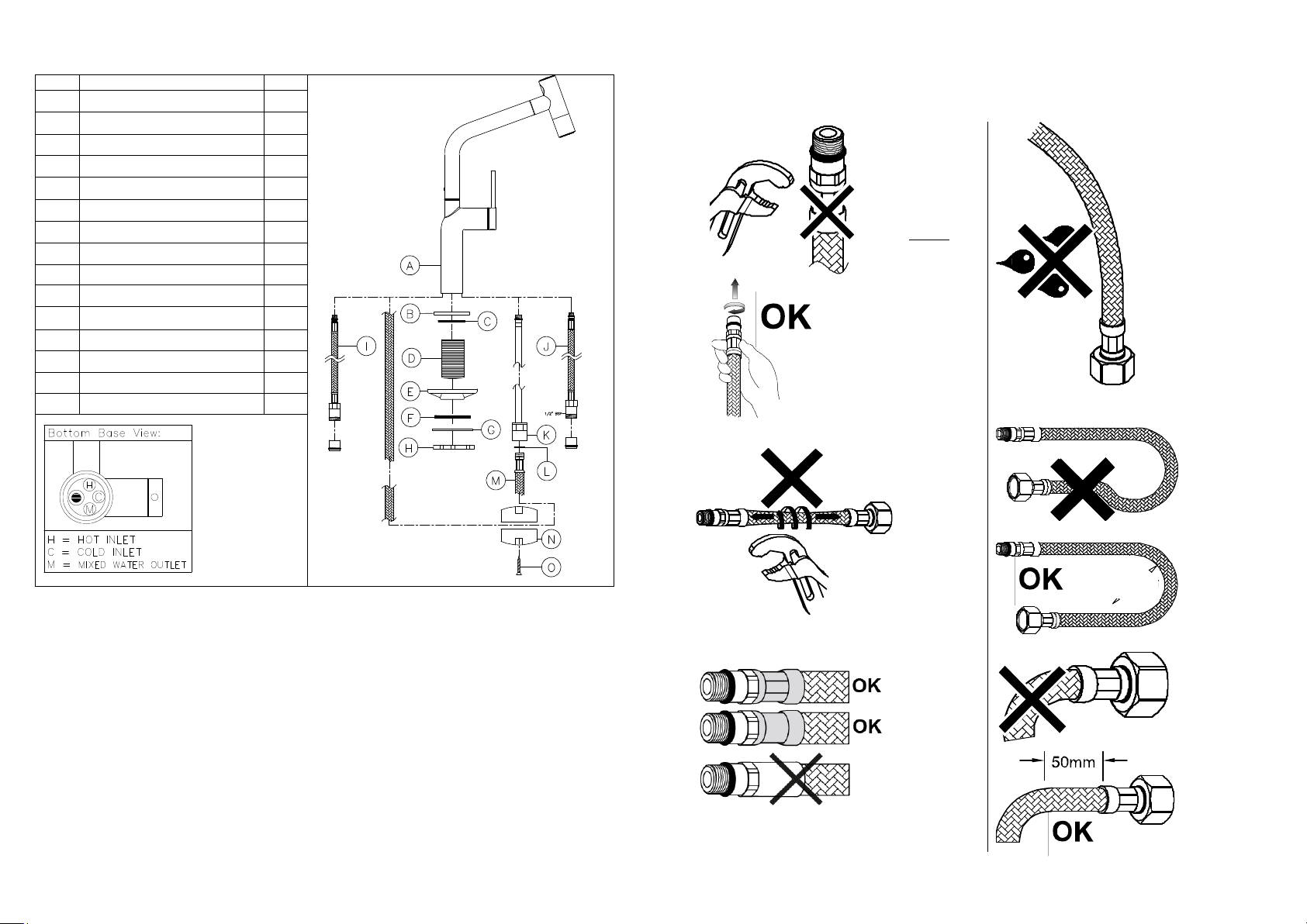
Installation:
1. Locate base plinth (B) onto the fine threaded side located on top of fixing column (D).
2. Place upper seal (C) under the recess in base plinth (B).
3. crew both the base plinth (B), upper seal (C) and fixing column (D) into the mixer body (A and over pull-out hose (M)), we
recommend gloves as the thread may have sharp edges.
4. crew the hot flexible hose (I) and cold flexible hose (J) into mixer body (A) hand tight, refer to figure 1 for the correct
inlets shown as “H” & “C”.
5. crew the mixed water outlet extension (K) into the mixed water outlet “M” as shown on figure 1. If using a spanner to
tighten extension (K) do not overtighten it as you may damage the seal on the top of the extension.
6. Place the mixer tap (A), with base plinth (B), upper seal (C) and fixing column (D) onto the sink/worktop, passing the
flexible hoses (I&J), mixed water outlet (K) and the pull-out hose (M) through the tap hole.
7. Pass the lower gasket (F), the metal spacer (G) and fixing nut (H) over the fixing column (D), flexible hoses (I, J & M)) and
mixed water outlet (K). Only If fitting the tap to a stainless-steel sink, the white triangular stabiliser (E) can be optionally
placed where shown to help stabilise the weight of the tap.
8. With the tap central to the tap hole hold it securely in place whilst fastening fixing nut (H) securely onto the fixing column
(D) to fix the tap (A) into its correct location.
9. Fully screw the pull-out hose (M) into the mixer water outlet extension (K) using a small spanner ensuring the seal (L) is in
place between the connection.
10. Fix the hose weight (N) with screws (O) as shown, it should be positioned at the lowest vertical point on hose (M) as the
hose returns upwards to the tap body (A).
11. Connect the hot and cold flexible hoses (I & J) to the water mains using ½” B Px15mm compression fittings. Note: Non-
return valves will be pre-inserted into flexible hoses (I & J).
After Installation:
Once you have visually checked the new fittings and connections, ensure that all taps and drains are closed except the new
product which should be left open. Turn on (reconnect) the water supplies, check carefully for leaks around the installation and
product function. Once you are sure of no leaks, close the new product and recheck for leaks, turn on the water heating power.
Clean and dry the product of any marks from installation then cover the product with the bag provided to protect it until use.
Important Technical Data
Minimum operating pressure: 1.25 bar
Maximum operating pressure: 5.5 bar*
Flow characteristics: ingle flow
Maximum hot water temperature: 60°C*
Recommended hot water temperature: 46°C
*If these temperatures or pressures are exceeded, even for short periods, damage can result and will void your warranty.
In these instances, reduce the incoming water temperature and or install a pressure reducing valve. Ensure that your Abode
product is fitted in accordance with Local Water Byelaws or regulations by a qualified installer.
These installation guidelines have been prepared for your direction and you must exercise due care at all times. We do not
accept responsibility for problems that may occur through improper installation. Whilst installing the product take care not to
accidentally loosen any screwed assemblies.
Manufacturers Product Reference: AT2190 ©Abode - 11/2021
Unit L, Zenith Park, Whaley Road, Barnsley, 75 1HT
Tel: (+44) 01226 283434 or www.abodedesigns.co.uk
All errors and omissions excepted.
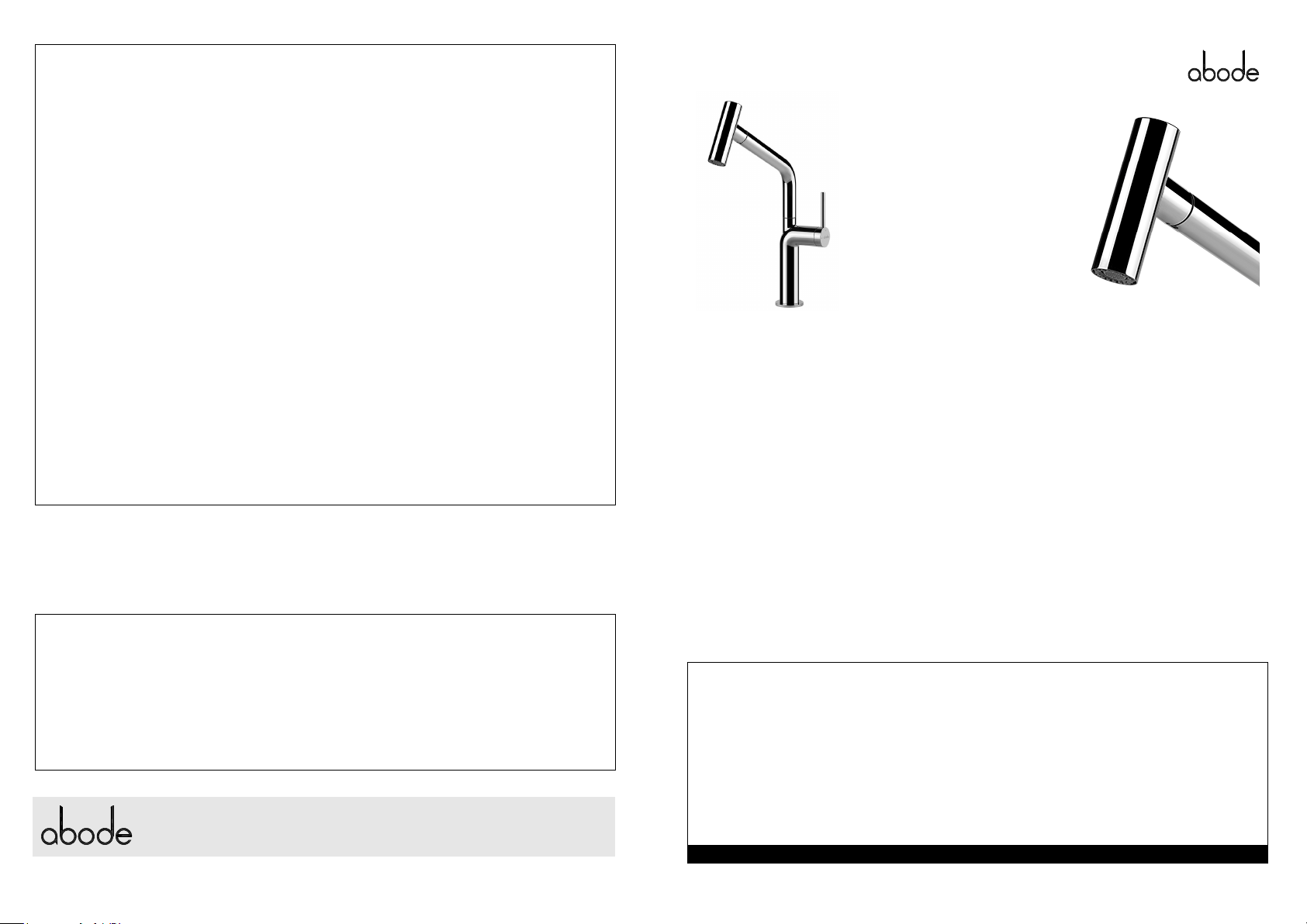
Tubist T Spray
Terms and Conditions:
In the unlikely event that you should experience any
defect in the materials or workmanship of your new
Abode product within 5 years of purchase, the
purchaser’s sole remedy shall be the replacement (at the
manufacturer’s discretion) of all or any part of the
product that is defective. All working parts and valves are
guaranteed for a period of 5 years from purchase.
Decorative surface finishes and O-rings are guaranteed
for 1 year from the date of purchase provided that our
advice concerning care has been observed and no
scouring agents have been used. This is provided that the
product has been used for normal domestic purposes
only and that the care, installation and maintenance
instructions have been observed. The warranty extends
to the original purchaser only.
Marks, scuffs and scratches caused by improper
installation or accidental damage are not covered by this
guarantee. Neither are shade variations or any damage
or defect caused by incorrect installation or abuse of the
fitting.
As we are continuously improving and developing our
range of products, finishes & colours, in the event of a
valid claim, we may not be able to provide an identical
replacement for the defective product throughout the
guarantee period. Where an identical product is no
longer available, we will supply the nearest equivalent
from our then current product range. In assessing your
claim, we must be given the opportunity to discuss your
claim, review your proof of purchase and or inspect the
product as installed prior to removal. Any agreed product
return must be packaged as received and complete.
No other warranties, express or implied, are made,
including merchantability or fitness for a particular
purpose. Under no circumstances shall the manufacturer
be liable for any loss or damage arising from the
purchase, use or inability to use this product, or for any
special, indirect, incidental or consequential damages.
No liability is accepted for consequential damage to
other household fixtures, fittings or furnishings arising
from this claim, even if attached to the product. No
installer, dealer, agent or employee of Abode has the
authority to modify the obligations or limitations of this
warranty.
Important Care Instructions for your Product:
To maintain the appearance of this product, ensure that it is regularly cleaned only using a clean, soft damp cloth. A solution
of warm water and a mild liquid detergent may be used where necessary, and then the fitting rinsed thoroughly and wiped
dry. Any other cleaning action or use of common domestic cleaning products will invalidate your warranty.
If the product has a plastic aerator insert at the end of the spout it should be unscrewed and the plastic internal insert only
removed and cleaned or descaled to maintain flow performance. Do not use descaling solution on any decorative metal
housing, rinse the insert thoroughly before reattaching in the reverse order.
Abrasive cleaners, scouring cleaners and acidic cleaners must not be used on this product under any circumstances. Avoid
contact with all solvents (including chlorinated solvents, ketones or acetones as these may result in surface deterioration or
etching). Also avoid contact with any harsh household chemicals such as oven cleaners, drain cleaners, rust removers, paint
strippers and toilet bowl cleaners, bar keepers friend or Brasso.
Please leave these instructions for your customer.