ADS StormTech SC-160LP Guide

Call StormTech at 860.529.8188 or 888.892.2694 or visit our website at www.stormtech.com for technical and product information. 1
StormTech MC-3500 Chamber
SC-160LP, SC-310, SC-740
& DC-780 Design Manual
THE MOST ADVANCED NAME IN WATER MANAGEMENT SOLUTIONS ®
StormTech®Chamber Systems for Stormwater Management

An company
TOOL 2.0
DESIGN
$
StormTech Design Tool Sell Sheet VERSION 4, 04-19.indd 1 5/2/2019 10:43:08 AM

Call StormTech at 860.529.8188 or 888.892.2694 or visit our website at www.stormtech.com for technical and product information. 1
Table of Contents
1.0 Introduction ..............................................................................2
2.0 Product Information . . . . . . . . . . . . . . . . . . . . . . . . . . . . . . . . . . . . . . . . . . . . . . . . . . . . . . . . . . . . . . . . . . . . . . . .3
3.0 Structural Capabilities .....................................................................15
4.0 Foundation for Chambers...................................................................17
5.0 Cumulative Storage Volume ................................................................ 20
6.0 Required Materials/Row Separation ......................................................... 22
7.0 Inletting the Chambers.................................................................... 23
8.0 Outlets for Chambers ..................................................................... 26
9.0 Other Considerations ..................................................................... 27
10.0 System Sizing........................................................................... 28
11.0 Detail Drawings ......................................................................... 29
12.0 Inspection and Maintenance ............................................................... 30
13.0 General Notes............................................................................32
14.0 StormTech Product Specifications........................................................... 33
15.0 Chamber Specifications for Contract Documents ............................................... 34
* For MC-3500 and MC-4500 designs, please refer to the MC-3500/MC-4500 Design Manual.
The StormTech Technical Services Department assists design professionals in specifying StormTech storm water systems. This assistance
includes the layout of chambers to meet the engineer’s volume requirements and the connections to and from the chambers. The
Technical Department can also assist converting and cost engineering projects currently specified with ponds, pipe, concrete and other
manufactured storm water detention/retention products. Please note that it is the responsibility of the design engineer to ensure that the
chamber bed layout meets all design requirements and is in compliance with applicable laws and regulations governing this project.
This manual is exclusively intended to assist engineers in the design of subsurface stormwater systems using StormTech chambers.

Call StormTech at 860.529.8188 or 888.892.2694 or visit our website at www.stormtech.com for technical and product information.
2
1.0 Introduction
1.1 INTRODUCTION
StormTech stormwater management systems allow
storm water professionals to create more protable,
environmentally sound developments. Compared with
other subsurface systems, StormTech systems offer
lower overall installed cost, superior design exibility and
enhanced performance. Applications include commercial,
residential, agricultural and highway drainage.
StormTech has invested over $10 million and many years
in the development of StormTech chambers. These
innovative products exceed the rigorous requirements
of the standards governing the design of thermoplastic
structures.
1.2 THE GOLD STANDARD IN STORMWATER
MANAGEMENT
The advanced designs of StormTech chambers were
created by implementing an aggressive research,
development, design and manufacturing protocol.
StormTech chamber products establish the new gold
standard in stormwater management through:
• Collaborations with experts in the eld of buried plastic
structures and polyolen materials
• The development and utilization of new testing methods
and proprietary test methods
• The use of thermoformed prototypes to verify
engineering models, perform in-ground testing and
install observation sites
• The investment in custom-designed, injection molding
equipment
• The utilization of polypropylene and polyethylene as
manufacturing materials
• The design of molded-in features not possible with
traditional thermoformed chambers
Section 3.0 of this design manual, Structural Capabilities,
provides a detailed description of the research,
development and design process.
Many of StormTech’s unique chamber features can
benet a site developer, stormwater system designer,
and installer. Where applicable, StormTech Product
Specications are referenced throughout this design
manual. If StormTech’s unique product benets are
important to a stormwater system design, consider
including the applicable StormTech Product Specications
on the site plans. This can prevent substitutions with
inferior products. Refer to Section 14.0, StormTech
Product Specications.
1.3 PRODUCT QUALITY AND DESIGN TO
INTERNATIONAL STANDARDS
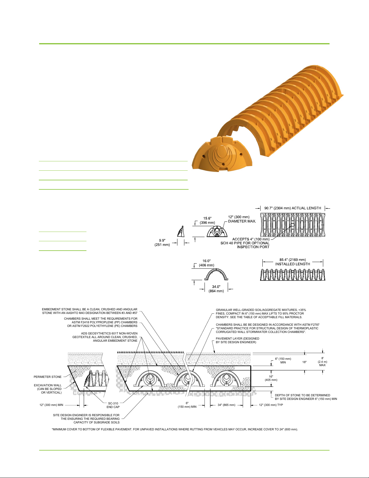
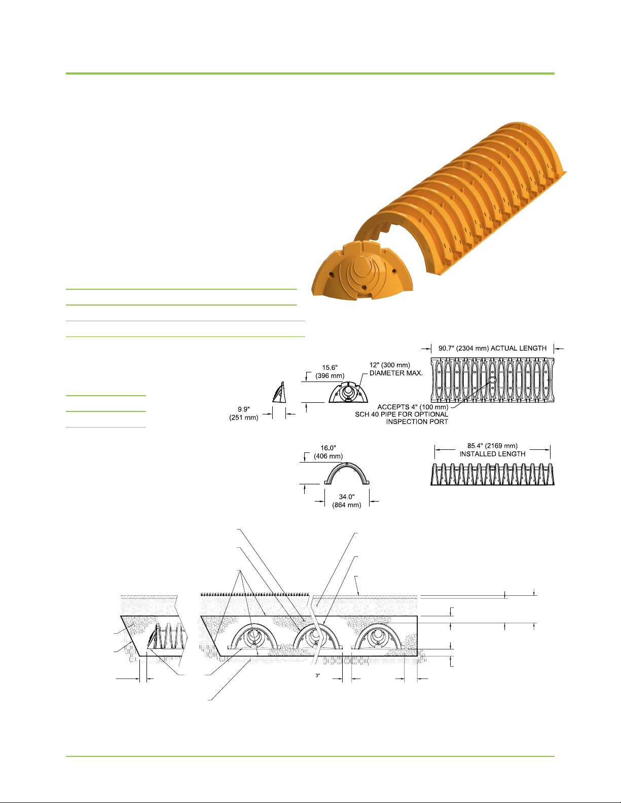
StormTech chambers are designed to meet the full scope
of design requirements of Section 12.12 of the AASHTO
LRFD Bridge Design Specications and produced to the
requirements of the American Society of Testing Materials
(ASTM) International specications F2418 (polypropylene
chambers) and F2922 (polyethylene chambers).
StormTech chambers provide the full AASHTO safety
factors for live loads and permanent earth loads. The two
ASTM standards mentioned previously are linked to the
AASHTO LRFD Bridge Design Specications Section
12.12 design standard. Both ASTM standards require that
the safety factors included in the AASHTO guidance are
achieved as a prerequisite to meeting either ASTM F2418
or ASTM F2922. StormTech chambers are also designed
in accordance with ASTM F2787, “Standard Practice
for Structural Design of Thermoplastic Corrugated
Wall Stormwater Collection Chambers” which provides
specic guidance on how to design thermoplastic
chambers in accordance with AASHTO Section 12.12.
These standards provide both the assurance of product
quality and safe structural design.
For non-proprietary specications for public bids that
ensure high product quality and safe design, consider
including the specication in Section 15.0 Chamber
Specications for Contract Documents.
1.4 TECHNICAL SUPPORT FOR PLAN REVIEWS
StormTech’s in-house technical support staff is available
to review proposed plans that incorporate StormTech
chamber systems. They are also available to assist with
plan conversions from existing products to StormTech.
Not all plan sheets are necessary for StormTech’s review.
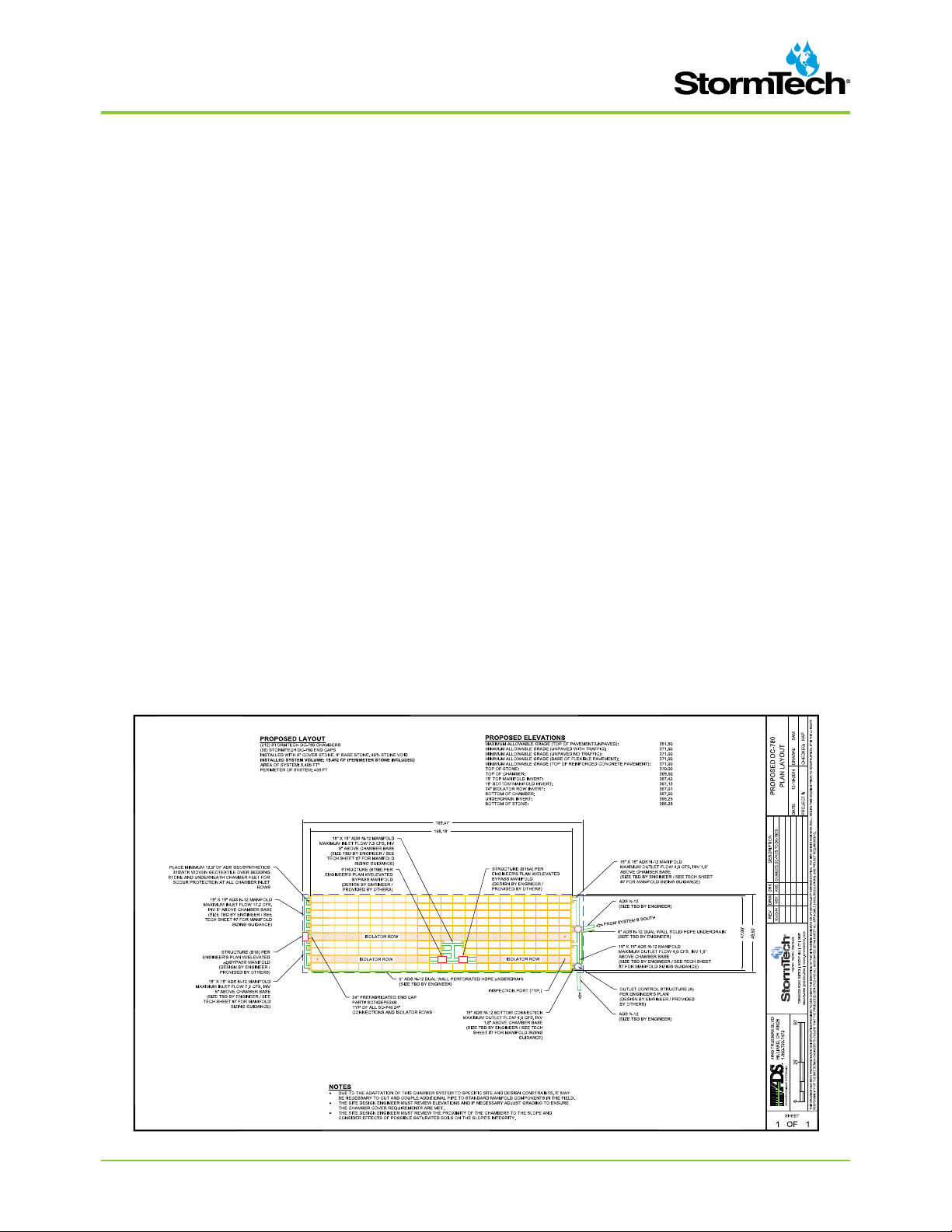
Required sheets include plan view sheet(s) with design
contours, cross sections of the stormwater system
including catch basins and drainage details.
When specifying StormTech chambers it is recommended
that the following items are included in project plans:
StormTech chamber system General Notes, applicable
StormTech chamber illustrations and StormTech chamber
system Product Specications. These items are available
in various formats and can be obtained by contacting
StormTech at 1-860-529-8188 or may be downloaded at
www.stormtech.com.
StormTech’s plan review is limited to the sole purpose
of determining whether plans meet StormTech chamber
systems’ minimum requirements. It is the ultimate
responsibility of the design engineer to assure that
the stormwater system’s design is in full compliance
with all applicable laws and regulations. StormTech
products must be designed and installed in accordance
with StormTech’s minimum requirements.
SEND PLANS TO:
E-mail: info@stormtech.com.

Call StormTech at 860.529.8188 or 888.892.2694 or visit our website at www.stormtech.com for technical and product information. 3
2.0 Product Information
2.1 PRODUCT APPLICATIONS
StormTech chamber systems may function as stormwater
detention, retention, rst-ush storage, or some
combination of these. The StormTech chambers can be
used for commercial, municipal, industrial, recreational,
and residential applications especially for installations
under parking lots and commercial roadways.
One of the key advantages of the StormTech chamber
system is its design exibility. Chambers may be
congured into beds or trenches of various sizes or
shapes. They can be centralized or decentralized, and t
on nearly all sites. Chamber lengths enhance the ability to
develop on both existing and pre-developed projects. The
systems can be designed easily and efciently around
utilities, natural or man-made structures and any other
limiting boundaries.
2.2 CHAMBERS FOR STORMWATER DETENTION
Chamber systems have been used effectively for storm
water detention for over 15 years. A detention system
temporarily holds water while it is released at a dened
rate through an outlet. While some inltration may
occur in a detention system, it is often considered an
environmental benet and a storage safety factor. Over
70% of StormTech’s installations are non-watertight
detention systems. There are only a few uncommon
situations where a detention system might need to
limit inltration: the subgrade soil’s bearing capacity is
signicantly affected by saturation such as with expansive
clays or karst soils, and; in sensitive aquifer areas where
the depth to groundwater does not meet local guidelines.
Adequate pretreatment could eliminate concerns for the
latter case. A thermoplastic liner may be considered for
both situations to limit inltration.
2.3 STONE POROSITY ASSUMPTION
A StormTech chamber system requires the application
of clean, crushed, angular stone below, between and
above the chambers. This stone serves as a structural
component while allowing conveyance and storage of
stormwater. Storage volume examples throughout this
Design Manual are calculated with an assumption that
the stone has an industry standard porosity of 40%.
Actual stone porosity may vary. Contact StormTech for
information on calculating storm water volumes with
varying stone porosity assumptions.
2.4 CHAMBER SELECTION
Primary considerations when selecting between the SC-
160LP, SC-310, SC-740 and DC-780 chambers are the
depth to restrictive layer, available area for subsurface
storage, cover height and outfall restrictions.
The StormTech SC-160LP chamber shown on page
4 is the smallest of the chamber family and has been
optimized to t in the shallowest of applications. This
extra low prole chamber allows for storage of 1.01 ft3/ft2
(0.3m3/m2) [minimum] of storage.
The SC-310 and SC-740 chambers and end plates.
StormTech systems can be integrated into retrot and
new construction projects.
The StormTech SC-310 chamber shown on page 6 is ideal
for systems requiring low-rise and wide-span solutions.
This low prole chamber allows the storage of large
volumes, 1.3 ft3/ft2(0.40 m3/m2) [minimum], at minimum
depths.
Like the Stormtech SC-310, the StormTech SC-310-
3 found on page 8 allows for a design option for sites
with both limited cover and limited space. With only 3”
of spacing between the chambers, the SC-310-3 still
provides 1.3 ft3/ft2(0.40 m3/m2) [minimum] of storage.
The StormTech SC-740 chamber shown on page 10
optimizes storage volumes in relatively small footprints.
By providing 2.2 ft3/ft2 (0.67 m3/m2) [minimum] of storage,
the SC-740 chambers can minimize excavation, backll
and associated costs.
The DC-780 chamber shown on page 12 has been
developed for those applications which exceed the
maximum 8 ft (2.44 m) burial depth of the SC-740 and SC-
310 chambers. The DC-780 is a modied version of the
SC-740 allowing it to reach a maximum burial depth of 12
ft (3.66 m). The design of the DC-780 chamber, like other
StormTech chambers, is designed and manufactured
in accordance with the AASHTO LRFD Bridge Design
Specications as well as ASTM F 2418 and ASTM F 2787
ensuring structural adequacy for deeper systems.
The end corrugations of the DC-780 chamber have not
been modied in order to allow connections to the SC-740
chamber. This will allow hybrid systems utilizing both
chambers in one system design.

Call StormTech at 860.529.8188 or 888.892.2694 or visit our website at www.stormtech.com for technical and product information.
4
StormTech SC-160LP Chamber
Shipping
132 chambers/pallet
144 end caps/pallet
12 pallets/truck
StormTech SC-160LP (not to scale)
Nominal Chamber Specifications
Size (LxWxH) 85.4” x 25.0” x 12.0” (2170 x 635 x 305 mm)
Chamber Storage 6.85 ft3(0.19 m3)
Min. Installed Storage* 15.0 ft3(0.42 m3)
Weight 24.0 lbs. (10.9 kg)
*Assumes 6” (150 mm) stone above, 4” (100 mm) below and stone between
chambers with 40% stone porosity
THE INSTALLED CHAMBER SYSTEM SHALL PROVIDE THE LOAD FACTORS SPECIFIED IN THE AASHTO LRFD BRIDGE DESIGN SPECIFICATIONS SECTION 12.12 FOR EARTH AND LIVE LOADS, WITH
CONSIDERATION FOR IMPACT AND MULTIPLE VEHICLE PRESENCES.
14"
(350 mm)
MIN*
10'
(3.0 m)
MAX
6" (150 mm)
MIN
12" (300 mm) MIN
25"
(635 mm)
12" (300 mm)
TYP
DEPTH OF STONE TO BE DETERMINED
BY SITE DESIGN ENGINEER 4" (100 mm) MIN
WITH GEOGRID BX124GG
12"
(300 mm)
*MINIMUM COVER TO BOTTOM OF FLEXIBLE PAVEMENT. FOR UNPAVED INSTALLATIONS WHERE RUTTING FROM VEHICLES MAY OCCUR, INCREASE COVER TO 20" (510 mm).
SC-160LP
END CAP
NO SPACING REQUIRED
BETWEEN CHAMBERS
SINGLE LAYER OF GEOGRID BX124GG TO BE INSTALLED
BETWEEN NON WOVEN GEOTEXTILE AND BASE STONE
PERIMETER STONE
EXCAVATION WALL
(CAN BE SLOPED
OR VERTICAL)
SITE DESIGN ENGINEER IS RESPONSIBLE FOR
THE ENSURING THE REQUIRED BEARING
CAPACITY OF SUBGRADE SOILS
PAVEMENT LAYER (DESIGNED
BY SITE DESIGN ENGINEER)
CHAMBERS SHALL BE BE DESIGNED IN ACCORDANCE WITH ASTM F2787
"STANDARD PRACTICE FOR STRUCTURAL DESIGN OF THERMOPLASTIC
CORRUGATED WALL STORMWATER COLLECTION CHAMBERS".
GRANULAR WELL-GRADED SOIL/AGGREGATE MIXTURES, <35%
FINES, COMPACT IN 6" (150 mm) MAX LIFTS TO 95% PROCTOR
DENSITY. SEE THE TABLE OF ACCEPTABLE FILL MATERIALS.
ADS GEOSYTHETICS 601T NON-WOVEN
GEOTEXTILE ALL AROUND CLEAN, CRUSHED,
ANGULAR EMBEDMENT STONE
CHAMBERS SHALL MEET THE REQUIREMENTS FOR
ASTM F2418 POLYPROPLENE (PP) CHAMBERS
OR ASTM F2922 POLYETHYLENE (PE) CHAMBERS
EMBEDMENT STONE SHALL BE A CLEAN, CRUSHED AND ANGULAR
STONE WITH AN AASHTO M43 DESIGNATION BETWEEN #3 AND #57
Designed to meet the most stringent industry performance standards for superior structural
integrity while providing designers with a cost-effective method to save valuable land and
protect water resources. The StormTech system is designed primarily to be used under
parking lots, thus maximizing land usage for commercial and municipal applications.
StormTech chambers can also be used in conjunction with Green Infrastructure, thus
enhancing the performance and extending the service life of these practices.
The SC-160LP chamber was developed for inltration and detention in shallow cover
applications
• Only 14” (350 mm) required from top of chamber to bottom of pavement
• Only 12” (300 mm) tall
• Installs toe to toe—no additional spacing between rows

5
SC-160LP Cumlative Storage Volumes per chamber
Assumes 40% Stone Porosity. Calculations are Based Upon a 4”
(100 mm) Stone Base Under Chambers.
Note: Add 0.49 ft3(0.014 m3) of storage for each additional inch (25 mm) of stone
foundation.
Depth of Water in
System Inches (mm)
Cumulative Chamber
Storage ft3 (m3)
Total System Cumulative
Storage ft3 (m3)
22 (559) 6.85 (0.194) 14.98 (0.424)
21 (533) 6.85 (0.194) 14.49 (0.410)
20 (508) 6.85 (0.194) 14.00 (0.396)
19 (483) 6.85 (0.194) 13.50 (0.382)
18 (457) 6.85 (0.194) 13.01 (0.368)
17 (432) 6.85 (0.194) 12.51 (0.354)
16 (406) 6.85 (0.194) 12.02 (0.340)
15 (381) 6.80 (0.193) 11.49 (0.325)
14 (356) 6.67 (0.189) 10.92 (0.309)
13 (330) 6.38 (0.181) 10.25 (0.290)
12 (305) 5.94 (0.168) 9.49 (0.269)
11 (279) 5.40 (0.153) 8.67 (0.246)
10 (254) 4.78 (0.135) 7.81 (0.221)
9 (229) 4.10 (0.116) 6.91 (0.196)
8 (203) 3.36 (0.095) 5.97 (0.169)
7 (178) 2.58 (0.073) 5.01 (0.142)
6 (152) 1.76 (0.050) 4.02 (0.114)
5 (127) 0.89 (0.025) 3.01 (0.085)
4 (102) 0 (0) 1.98 (0.056)
3 (76) 0 (0) 1.48 (0.042)
2 (51) 0 (0) 0.99 (0.028)
1 (25) 0 (0) 0.49 (0.014)
Stone
Foundation
Stone
Cover
ENGLISH TONS (yds3)
Stone Foundation Depth
4” 6” 8”
StormTech SC-160LP 1.1 (0.8) 1.2 (0.9) 1.3 (0.9)
METRIC KILOGRAMS (m3)100 mm 150 mm 200 mm
StormTech SC-160LP 952 (0.7) 1,074 (0.8) 1,197 (0.8)
Note: Assumes 6” (150 mm) of stone above and only embedment stone
between chambers.
Amount of Stone Per Chamber
Stone Foundation Depth
4” (100) 8” (200) 12” (300)
StormTech SC-160LP 1.4 (1.1) 1.6 (1.2) 1.8 (1.3)
Note: Assumes no row separation and 14” (350 mm) of cover. The volume of
excavation will vary as depth of cover increases.
Volume Excavation Per Chamber yd3(m3)

Call StormTech at 860.529.8188 or 888.892.2694 or visit our website at www.stormtech.com for technical and product information.
6
StormTech SC-310 Chamber
Shipping
41 chambers/pallet
108 end caps/pallet
18 pallets/truck
StormTech SC-310 Chamber (not to scale)
Nominal Chamber Specifications
Size (Lx W x H) 85.4” x 34.0” x 16.0” (2170 x 864 x 406 mm)
Chamber Storage 14.7 ft3(0.42 m3)
Min. Installed Storage* 31.0 ft3(0.88 m3)
Weight 37.0 lbs (16.8 kg)
*Assumes 6” (150 mm) stone above, below and between chambers and 40%
stone porosity.
THE INSTALLED CHAMBER SYSTEM SHALL PROVIDE THE LOAD FACTORS SPECIFIED IN THE AASHTO LRFD BRIDGE DESIGN SPECIFICATIONS SECTION 12.12 FOR EARTH AND LIVE LOADS, WITH
CONSIDERATION FOR IMPACT AND MULTIPLE VEHICLE PRESENCES.
18"
(450 mm) MIN*
8'
(2.4 m)
MAX
6" (150 mm)
MIN
12" (300 mm) MIN
12" (300 mm) TYP
34" (865 mm)
6"
(150 mm) MIN
16"
(405 mm)
DEPTH OF STONE TO BE DETERMINED
BY SITE DESIGN ENGINEER 6" (150 mm) MIN
SC-310
END CAP
PERIMETER STONE
EXCAVATION WALL
(CAN BE SLOPED
OR VERTICAL)
*MINIMUM COVER TO BOTTOM OF FLEXIBLE PAVEMENT. FOR UNPAVED INSTALLATIONS WHERE RUTTING FROM VEHICLES MAY OCCUR, INCREASE COVER TO 24" (600 mm).
SITE DESIGN ENGINEER IS RESPONSIBLE FOR
THE ENSURING THE REQUIRED BEARING
CAPACITY OF SUBGRADE SOILS
PAVEMENT LAYER (DESIGNED
BY SITE DESIGN ENGINEER)
CHAMBERS SHALL BE BE DESIGNED IN ACCORDANCE WITH ASTM F2787
"STANDARD PRACTICE FOR STRUCTURAL DESIGN OF THERMOPLASTIC
CORRUGATED WALL STORMWATER COLLECTION CHAMBERS".
GRANULAR WELL-GRADED SOIL/AGGREGATE MIXTURES, <35%
FINES, COMPACT IN 6" (150 mm) MAX LIFTS TO 95% PROCTOR
DENSITY. SEE THE TABLE OF ACCEPTABLE FILL MATERIALS.
ADS GEOSYTHETICS 601T NON-WOVEN
GEOTEXTILE ALL AROUND CLEAN, CRUSHED,
ANGULAR EMBEDMENT STONE
CHAMBERS SHALL MEET THE REQUIREMENTS FOR
ASTM F2418 POLYPROPLENE (PP) CHAMBERS
OR ASTM F2922 POLYETHYLENE (PE) CHAMBERS
EMBEDMENT STONE SHALL BE A CLEAN, CRUSHED AND ANGULAR
STONE WITH AN AASHTO M43 DESIGNATION BETWEEN #3 AND #57
Designed to meet the most stringent industry performance standards
for superior structural integrity while providing designers with a cost-
effective method to save valuable land and protect water resources.
The StormTech system is designed primarily to be used under parking
lots, thus maximizing land usage for private (commercial) and public
applications. StormTech chambers can also be used in conjunction with
Green Infrastructure, thus enhancing the performance and extending the
service life of these practices.

7
SC-310 CUMLATIVE STORAGE VOLUMES PER CHAMBER
Assumes 40% Stone Porosity. Calculations are Based Upon a
6” (150 mm) Stone Base Under Chambers.
Note: Add 0.79 ft3(0.022 m3) of storage for each additional inch. (25 mm) of stone
foundation.
Bare
Chamber
Storage
ft3(m3)
Chamber and Stone
Foundation Depth in. (mm)
6 (150) 12 (300) 18 (450)
StormTech SC-310 14.7 (0.4) 31.0 (0.9) 35.7 (1.0) 40.4 (1.1)
ENGLISH TONS (yds3)
Stone Foundation Depth
6” 12” 18”
StormTech SC-310 2.1 (1.5 yd3)2.7 (1.9 yd3)3.4 (2.4 yd3)
METRIC KILOGRAMS (m3)150 mm 300 mm 450 mm
StormTech SC-310 1,830 (1.1 m3)2,490 (1.5 m3)2,990 (1.8 m3)
Note: Assumes 6” (150 mm) of stone above, and between chambers.
Storage Volume Per Chamber ft3(m3)
Amount of Stone Per Chamber
Stone Foundation Depth
6” (150 mm) 12” (300 mm) 18” (450 mm)
StormTech SC-310 2.9 (2.2) 3.4 (2.6) 3.8 (2.9)
Note: Assumes 6” (150 mm) of row separation and 18” (450 mm) of cover. The
volume of excavation will vary as the depth of the cover increases.
Volume Excavation Per Chamber yd3(m3)
Note: Assumes 6” (150 mm) of stone above chambers, 6” (150 mm) row
spacing and 40% stone porosity.
Depth of Water in
System Inches (mm)
Cumulative Chamber
Storage ft3 (m3)
Total System Cumulative
Storage ft3 (m3)
28 (711) 14.70 (0.416) 31.00 (0.878)
27 (686) 14.70 (0.416) 30.21 (0.855)
26 (680) 14.70 (0.416) 29.42 (0.833)
25 (610) 14.70 (0.416) 28.63 (0.811)
24 (609) 14.70 (0.416) 27.84 (0.788)
23 (584) 14.70 (0.416) 27.05 (0.766)
22 (559) 14.70 (0.416) 26.26 (0.748)
21 (533) 14.64 (0.415) 25.43 (0.720)
20 (508) 14.49 (0.410) 24.54 (0.695)
19 (483) 14.22 (0.403) 23.58 (0.668)
18 (457) 13.68 (0.387) 22.47 (0.636)
17 (432) 12.99 (0.368) 21.25 (0.602)
16 (406) 12.17 (0.345) 19.97 (0.566)
15 (381) 11.25 (0.319) 18.62 (0.528)
14 (356) 10.23 (0.290) 17.22 (0.488)
13 (330) 9.15 (0.260) 15.78 (0.447)
12 (305) 7.99 (0.227) 14.29 (0.425)
11 (279) 6.78 (0.192) 12.77 (0.362)
10 (254) 5.51 (0.156) 11.22 (0.318)
9 (229) 4.19 (0.119) 9.64 (0.278)
8 (203) 2.83 (0.081) 8.03 (0.227)
7 (178) 1.43 (0.041) 6.40 (0.181)
6 (152) 04.74 (0.134)
5 (127) 03.95 (0.112)
4(102) 03.16 (0.090)
3 (76) 02.37 (0.067)
2 (51) 01.58 (0.046)
1 (25) 00.79 (0.022)
Stone Foundation
Stone
Cover

Call StormTech at 860.529.8188 or 888.892.2694 or visit our website at www.stormtech.com for technical and product information.
8
StormTech SC-310-3 Chamber
Shipping
41 chambers/pallet
108 end caps/pallet
18 pallets/truck
StormTech SC-310-3 Chamber (not to scale)
Nominal Chamber Specifications
Size (Lx W x H) 85.4” x 34.0” x 16.0” (2,170 x 864 x 406 mm)
Chamber Storage 14.7ft3(0.42 m3)
Min. Installed Storage* 29.3 ft3(0.83 m3)
Weight 37.0 lbs (16.8 kg)
*Assumes 6” (150 mm) stone above and below chambers, 3” (76 mm) row
spacing and 40% stone porosity.
THE INSTALLED CHAMBER SYSTEM SHALL PROVIDE THE LOAD FACTORS SPECIFIED IN THE AASHTO LRFD BRIDGE DESIGN SPECIFICATIONS SECTION 12.12 FOR EARTH AND LIVE LOADS, WITH CONSIDERATION
FOR IMPACT AND MULTIPLE VEHICLE PRESENCES.
16
"
(405 mm) MIN*
8
'
(
2.4 m
)
MAX
6
"
(
150 mm
)
M
IN
1
2" (300 mm) MIN
1
2" (300 mm) TYP34"
(
865 mm
)
(
75 mm
)
MIN
16"
(
405 mm
)
D
EPTH OF STONE TO BE DETERMINE
D
B
Y SITE DESIGN ENGINEER 6"
(
150 mm
)
MIN
SC
-
3
1
0
END
C
AP
PERIMETER
S
T
O
NE
E
X
C
AVATI
O
N WALL
(C
AN BE
S
L
O
PE
D
OR VERTICAL
)
*
MINIMUM COVER TO BOTTOM OF FLEXIBLE PAVEMENT. FOR UNPAVED INSTALLATIONS WHERE RUTTING FROM VEHICLES MAY OCCUR
,
INCREASE COVER
T
O 24"
(
600 mm
)
.
S
ITE DE
S
I
G
N EN
G
INEER I
S
RE
S
P
O
N
S
IBLE F
OR
THE ENSURING THE REQUIRED BEARIN
G
C
APACITY OF SUBGRADE SOILS
P
AVEMENT LAYER (DESIGNE
D
BY SITE DESIGN ENGINEER
)
C
HAMBER
S
S
HALL BE BE DE
S
I
G
NED IN A
CCO
RDAN
C
E WITH A
S
TM F27
87
"S
TANDARD PRA
C
TI
C
E F
O
R
S
TR
UC
T
U
RAL DE
S
I
G
N
O
F THERM
O
PLA
S
TI
C
CO
RR
UG
ATED WALL
S
T
O
RMWATER
CO
LLE
C
TI
O
N
C
HAMBER
S
".
GRANULAR WELL-GRADED SOIL/AGGREGATE MIXTURES
,
<35%
F
INES, COMPACT IN 6"
(
150 mm
)
MAX LIFTS TO 95% PROCTO
R
D
ENSITY. SEE THE TABLE OF ACCEPTABLE FILL MATERIALS.
A
D
S
G
E
OS
YTHETI
CS
60
1T N
O
N-W
O
VEN
G
EOTEXTILE ALL AROUND CLEAN, CRUSHED
,
A
NGULAR EMBEDMENT STONE
C
HAMBER
S
S
HALL MEET THE RE
Q
UIREMENT
S
F
OR
A
STM F2418 POLYPROPLENE
(
PP
)
CHAMBER
S
OR ASTM F2922 POLYETHYLENE
(
PE
)
CHAMBER
S
EMBEDMENT STONE SHALL BE A CLEAN
,
CRUSHED AND ANGULA
R
S
T
O
NE WITH AN AA
S
HT
O
M4
3
DE
S
I
G
NATI
O
N BETWEEN
#3
AND
#5
7
The proven strength and durability of the SC-310-3 Chamber allows for a
design option for sites where limited cover, limited space, high water table and
escalated aggregate cost are a factor. The SC-310-3 has a minimum cover
requirement of 16” (400 mm) to bottom of exible pavement and reduces the
spacing requirement between chambers by 50% to 3” (76 mm). This provides a
reduced footprint overall, reduces aggregate needed, and allows the designer
to offer a trafc bearing application yet comply with water table separation
regulations. StormTech chambers can also be used in conjunction with
Green Infrastructure, thus enhancing the performance and extending
the service life of these practices.

9
Note: Add 0.73 ft3(0.021 m3) of storage for each additional inch (25 mm) of stone
foundation.
Depth of Water in
System Inches (mm)
Cumulative Chamber
Storage ft3 (m3)
Total System Cumulative
Storage ft3 (m3)
28 (711) 14.70 (0.416) 29.34 (0.831)
27 (686) 14.70 (0.416) 28.60 (0.810)
26 (660) 14.70 (0.416) 27.87 (0.789)
25 (635) 14.70 (0.416) 27.14 (0.769)
24 (610) 14.70 (0.416) 26.41 (0.748)
23 (584) 14.70 (0.416) 25.68 (0.727)
22 (559) 14.70 (0.416) 24.95 (0.707)
21 (533) 14.64 (0.415) 24.18 (0.685)
20 (508) 14.49 (0.410) 23.36 (0.661)
19 (483) 14.22 (0.403) 22.47 (0.636)
18 (457) 13.68 (0.387) 21.41 (0.606)
17 (432) 12.99 (0.368) 20.25 (0.573)
16 (406) 12.17 (0.345) 19.03 (0.539)
15 (381) 11.25 (0.319) 17.74 (0.502)
14 (356) 10.23 (0.290) 16.40 (0.464)
13 (330) 9.15 (0.260) 15.01 (0.425)
12 (305) 7.99 (0.226) 13.59 (0.385)
11 (279) 6.78 (0.192) 12.13 (0.343)
10 (254) 5.51 (0.156) 10.63 (0.301)
9 (229) 4.19 (0.119) 9.11 (0.258)
8 (203) 2.83 (0.080) 7.56 (0.214)
7 (178) 1.43 (0.041) 5.98 (0.169)
6 (152) 0 (0) 4.39 (0.124)
5 (127) 0 (0) 3.66 (0.104)
4 (102) 0 (0) 2.93 (0.083)
3 (76) 0 (0) 2.19 (0.062)
2 (51) 0 (0) 1.46 (0.041)
1 (25) 0 (0) 0.73 (0.021)
Stone
Foundation
Stone
Cover
ENGLISH TONS (yds3)
Stone Foundation Depth
6” 12” 16”
SC-310-3 1.9 (1.4) 2.5 (1.8) 3.1 (2.2)
METRIC KILOGRAMS (m3)150 mm 300 mm 450 mm
SC-310-3 1,724 (1.0) 2,268 (1.3) 2,812 (1.7)
Note: Assumes 6” (150 mm) of stone above and and 3” (76 mm) row spacing.
Amount of Stone Per Chamber
Stone Foundation Depth
6 (150) 12 (300) 18 (450)
SC-310-3 2.6 (2.0) 3.0 (2.0) 3.4 (2.6)
Note: Assumes 3” (76 mm) of row separation and 6” (150 mm) of stone above
the chambers and 16” (400 mm) of cover. The volume of excavation will vary
as depth of cover increases
Volume Excavation Per Chamber yd3(m3)
Bare
Chamber
Storage
ft3(m3)
Chamber and Stone
Foundation Depth in. (mm)
6 (150) 12 (300) 18 (450)
SC-310-3 Chamber 14.7 (0.42) 29.3 (0.83) 33.7 (0.95) 38.1 (1.08)
Storage Volume Per Chamber ft3(m3)
Note: Assumes 6” (150 mm) of stone above chambers, 3” (76 mm) row
spacing and 40% stone porosity.
SC-310-3 CUMLATIVE STORAGE VOLUMES PER CHAMBER
Assumes 40% Stone Porosity. Calculations are Based Upon a 6”
(150 mm) Stone Base Under Chambers.

Call StormTech at 860.529.8188 or 888.892.2694 or visit our website at www.stormtech.com for technical and product information.
10
StormTech SC-740 Chamber
Shipping
30 chambers/pallet
60 end caps/pallet
12 pallets/truck
StormTech SC-740 Chamber (not to scale)
Nominal Chamber Specifications
Size (Lx W x H) 85.4” x 51.0” x 30.0” (2,170 x 1,295 x 762 mm)
Chamber Storage 45.9 ft3(1.30 m3)
Min. Installed Storage* 74.9 ft3(2.12 m3)
Weight 74.0 lbs (33.6 kg)
*Assumes 6” (150 mm) stone above, below and between chambers and
40% stone porosity.
THE INSTALLED CHAMBER SYSTEM SHALL PROVIDE THE LOAD FACTORS SPECIFIED IN THE AASHTO LRFD BRIDGE DESIGN SPECIFICATIONS SECTION 12.12 FOR EARTH AND LIVE LOADS, WITH
CONSIDERATION FOR IMPACT AND MULTIPLE VEHICLE PRESENCES.
18"
(450 mm) MIN*
8'
(2.4 m)
MAX
51" (1295 mm)
6" (150 mm) MIN
6"
(150 mm) MIN
12" (300 mm) TYP
30"
(760 mm)
DEPTH OF STONE TO BE DETERMINED
BY SITE DESIGN ENGINEER 6" (150 mm) MIN
12" (300 mm) MIN
SITE DESIGN ENGINEER IS RESPONSIBLE FOR
THE ENSURING THE REQUIRED BEARING
CAPACITY OF SUBGRADE SOILS
PAVEMENT LAYER (DESIGNED
BY SITE DESIGN ENGINEER)
CHAMBERS SHALL BE BE DESIGNED IN ACCORDANCE WITH ASTM F2787
"STANDARD PRACTICE FOR STRUCTURAL DESIGN OF THERMOPLASTIC
CORRUGATED WALL STORMWATER COLLECTION CHAMBERS".
GRANULAR WELL-GRADED SOIL/AGGREGATE MIXTURES, <35%
FINES, COMPACT IN 6" (150 mm) MAX LIFTS TO 95% PROCTOR
DENSITY. SEE THE TABLE OF ACCEPTABLE FILL MATERIALS.
ADS GEOSYTHETICS 601T NON-WOVEN
GEOTEXTILE ALL AROUND CLEAN, CRUSHED,
ANGULAR EMBEDMENT STONE
CHAMBERS SHALL MEET THE REQUIREMENTS FOR
ASTM F2418 POLYPROPLENE (PP) CHAMBERS
OR ASTM F2922 POLYETHYLENE (PE) CHAMBERS
EMBEDMENT STONE SHALL BE A CLEAN, CRUSHED AND ANGULAR
STONE WITH AN AASHTO M43 DESIGNATION BETWEEN #3 AND #57
PERIMETER STONE
EXCAVATION WALL
(CAN BE SLOPED
OR VERTICAL)
SC-740
END CAP
*MINIMUM COVER TO BOTTOM OF FLEXIBLE PAVEMENT. FOR UNPAVED INSTALLATIONS WHERE RUTTING FROM VEHICLES MAY OCCUR, INCREASE COVER TO 24" (600 mm).
Designed to meet the most stringent industry performance standards
for superior structural integrity while providing designers with a cost-
effective method to save valuable land and protect water resources.
The StormTech system is designed primarily to be used under parking
lots, thus maximizing land usage for private (commercial) and public
applications. StormTech chambers can also be used in conjunction
with Green Infrastructure, thus enhancing the performance and
extending the service life of these practices.

11
Note: Add 1.13 ft3(0.032 m3) of storage for each additional inch (25 mm) of stone
foundation.
Depth of Water in
System Inches (mm)
Cumulative Chamber
Storage ft3 (m3)
Total System Cumulative
Storage ft3 (m3)
42 (1067) 45.90 (1.300) 74.90 (2.121)
41 (1041) 45.90 (1.300) 73.77 (2.089)
40 (1016) 45.90 (1.300) 72.64 (2.057)
39 (991) 45.90 (1.300) 71.52 (2.025)
38 (965) 45.90 (1.300) 70.39 (1.993)
37 (940) 45.90 (1.300) 69.26 (1.961)
36 (914) 45.90 (1.300) 68.14 (1.929)
35 (889) 45.85 (1.298) 66.98 (1.897)
34 (864) 45.69 (1.294) 65.75 (1.862)
33 (838) 45.41 (1.286) 64.46 (1.825)
32 (813) 44.81 (1.269) 62.97 (1.783)
31 (787) 44.01 (1.246) 61.36 (1.737)
30 (762) 43.06 (1.219) 59.66 (1.689)
29 (737) 41.98 (1.189) 57.89 (1.639)
28 (711) 40.80 (1.155) 56.05 (1.587)
27 (686) 39.54 (1.120) 54.17 (1.534)
26 (660) 38.18 (1.081) 52.23 (1.479)
25 (635) 36.74 (1.040) 50.23 (1.422)
24 (610) 35.22 (0.977) 48.19 (1.365)
23 (584) 33.64 (0.953) 46.11 (1.306)
22 (559) 31.99 (0.906) 44.00 (1.246)
21 (533) 30.29 (0.858) 1.85 (1.185)
20 (508) 28.54 (0.808) 39.67 (1.123)
19 (483) 26.74 (0.757) 37.47 (1.061)
18 (457) 24.89 (0.705) 35.23 (0.997)
17 (432) 23.00 (0.651) 32.96 (0.939)
16 (406) 21.06 (0.596) 30.68 (0.869)
15 (381) 19.09 (0.541) 28.36 (0.803)
14 (356) 17.08 (0.484) 26.03 (0.737)
13 (330) 15.04 (0.426) 23.68 (0.670)
12 (305) 12.97 (0.367) 21.31 (0.608)
11 (279) 10.87 (0.309) 18.92 (0.535)
10 (254) 8.74 (0.247) 16.51 (0.468)
9 (229) 6.58 (0.186) 14.09 (0.399)
8 (203) 4.41 (0.125) 11.66 (0.330)
7 (178) 2.21 (0.063) 9.21 (0.264)
6 (152) 0 (0) 6.76 (0.191)
5 (127) 0 (0) 5.63 (0.160)
4 (102) 0 (0) 4.51 (0.128)
3 (76) 0 (0) 3.38 (0.096)
2 (51) 0 (0) 2.25 (0.064)
1 (25) 0 (0) 1.13 (0.032)
Stone
Foundation
Stone
Cover
ENGLISH TONS (yds3)
Stone Foundation Depth
6” 12” 16”
SC-740 3.8 (2.8) 4.6 (3.3) 5.5 (3.9)
METRIC KILOGRAMS (m3)150 mm 300 mm 450 mm
SC-740 3,450 (2.1) 4,170 (2.5) 4,490 (3.0)
Note: Assumes 6” (150 mm) of stone above and between chambers.
Amount of Stone Per Chamber
Stone Foundation Depth
6 (150) 12 (300) 18 (450)
SC-740 5.5 (4.2) 6.2 (4.7) 6.8 (5.2)
Note: Assumes 6” (150 mm) of row separation and 18” (450 mm) of cover. The
volume of excavation will vary as depth of cover increases.
Volume Excavation Per Chamber yd3(m3)
Bare
Chamber
Storage
ft3(m3)
Chamber and Stone
Foundation Depth in. (mm)
6 (150) 12 (300) 18 (450)
SC-740 Chamber 45.9 (1.3) 74.9 (2.1) 81.7 (2.3) 88.4 (2.5)
Storage Volume Per Chamber ft3(m3)
Note: Assumes 6” (150 mm) stone above chambers, 6” (150 mm) row
spacing and 40% stone porosity.
SC-740 CUMLATIVE STORAGE VOLUMES PER CHAMBER
Assumes 40% Stone Porosity. Calculations are Based Upon a 6”
(150 mm) Stone Base Under Chambers.
Call StormTech at 860.529.8188 or 888.892.2694 or visit our website at www.stormtech.com for technical and product information.

Call StormTech at 860.529.8188 or 888.892.2694 or visit our website at www.stormtech.com for technical and product information.
12
StormTech DC-780 Chamber
Shipping
24 chambers/pallet
60 end caps/pallet
12 pallets/truck
StormTech DC-780 Chamber (not to scale)
Nominal Chamber Specifications
Size (Lx W x H) 85.4” x 51.0” x 30.0” (2169 x 1295 x 762 mm)
Chamber Storage 46.2 ft3(1.30 m3)
Min. Installed Storage* 78.4 ft3(2.2 m3)
*Assumes 9” (230 mm) stone below, 6” (150 mm) stone above, 6”
(150 mm) row spacing and 40% stone porosity.
THE INSTALLED CHAMBER SYSTEM SHALL PROVIDE THE LOAD FACTORS SPECIFIED IN THE AASHTO LRFD BRIDGE DESIGN SPECIFICATIONS SECTION 12.12 FOR EARTH AND LIVE LOADS, WITH
CONSIDERATION FOR IMPACT AND MULTIPLE VEHICLE PRESENCES.
18
"
(450 mm) MIN*
12
'
(
3.7 m
)
MAX
51"
(
1295 mm
)
6"
(
150 mm
)
MI
N
6
"
(
150 mm
)
MI
N
12"
(
300 mm
)
TY
P
30
"
(
760 mm
)
D
EPTH
O
F
S
T
O
NE T
O
BE DETERMINE
D
BY
S
ITE DE
S
I
G
N EN
G
INEER 9"
(
230 mm
)
MI
N
1
2"
(
300 mm
)
MI
N
S
ITE DE
S
I
G
N EN
G
INEER I
S
RE
S
P
O
N
S
IBLE F
OR
THE ENSURING THE REQUIRED BEARIN
G
C
APA
C
ITY
O
F
S
UB
G
RADE
SO
IL
S
PAVEMENT LAYER
(
DE
S
I
G
NE
D
BY
S
ITE DE
S
I
G
N EN
G
INEER
)
C
HAMBER
S
S
HALL BE BE DE
S
I
G
NED IN A
CCO
RDAN
C
E WITH A
S
TM F27
87
"
S
TANDARD PRA
C
TI
C
E F
O
R
S
TRU
C
TURAL DE
S
I
G
N
O
F THERM
O
PLA
S
TI
C
CO
RR
UG
ATED WALL
S
T
O
RMWATER
CO
LLE
C
TI
O
N
C
HAMBER
S
"
.
G
RANULAR WELL-
G
RADED
SO
IL
/
A
GG
RE
G
ATE MIXTURE
S,
<35
%
FINE
S
,
CO
MPA
C
T IN 6"
(
150 mm
)
MAX LIFT
S
T
O
95
%
PR
OC
T
OR
DEN
S
ITY.
S
EE THE TABLE
O
F A
CC
EPTABLE FILL MATERIAL
S.
A
D
S
G
E
OS
YTHETI
CS
60
1T N
O
N-W
O
VE
N
G
E
O
TEXTILE ALL AR
O
UND
C
LEAN,
C
RU
S
HED
,
A
N
GU
LAR EMBEDMENT
S
T
O
N
E
C
HAMBER
S
S
HALL MEET A
S
TM F241
8
"
S
TANDAR
D
S
PE
C
IFI
C
ATI
O
N F
O
R P
O
LYPR
O
PLENE
(
PP
)
CO
RRU
G
ATE
D
W
ALL
S
T
O
RMWATER
CO
LLE
C
TI
O
N
C
HAMBER
S
"
.
E
MBEDMENT
S
T
O
NE
S
HALL BE A
C
LEAN,
C
RU
S
HED AND AN
G
ULA
R
S
T
O
NE WITH AN AA
S
HT
O
M4
3
DE
S
I
G
NATI
O
N BETWEEN
#3
AND
#57
PERIMETER
S
T
O
N
E
EX
C
AVATI
O
N WAL
L
(C
AN BE
S
L
O
PE
D
OR VERTICAL
)
SC
-74
0/
D
C
-7
80
END
C
A
P
*MINIMUM COVER TO BOTTOM OF FLEXIBLE PAVEMENT. FOR UNPAVED INSTALLATIONS WHERE RUTTING FROM VEHICLES MAY OCCUR, INCREASE COVER TO 24"
(
600 mm
).
Designed to meet the most stringent industry performance standards for superior
structural integrity while providing designers with a cost-effective method to save
valuable land and protect water resources. The StormTech system is designed
primarily to be used under parking lots, thus maximizing land usage for private
(commercial) and public applications. StormTech chambers can also be used
in conjunction with Green Infrastructure, thus enhancing the performance and
extending the service life of these practices.
• 12’ (3.6 m) Deep Cover Applications
• Designed in accordance with ASTM F2787 and produced to
meet the ASTM 2418 product standard.
• AASHTO safety factors provided for AASHTO Design Truck
(H20 and deep cover conditions.)

13
DC-780 Cumulative Storage Volumes Per Chamber
Assumes 40% Stone Porosity. Calculations are Based Upon a 9” (230 mm) Stone Base Under Chambers.
Note: Add 1.13 ft3(0.032 m3) of Storage for Each Additional Inch (25 mm) of
Stone Foundation.
Bare
Chamber
Storage
ft3(m3)
Chamber and Stone
Foundation Depth in. (mm)
9” (230 mm) 12” (300 mm) 18” (450 mm)
DC-780 Chamber 78.4 (2.2) 78.4 (2.2) 81.8 (2.3) 88.6 (2.5)
ENGLISH TONS (yds3)
Stone Foundation Depth
9” 12” 18”
DC-780 Chamber 4.2 (3.0) 4.7 (3.3) 5.6 (3.9)
METRIC KILOGRAMS (m3)230 mm 300 mm 450 mm
DC-780 Chamber 3,810 (2.3) 4,264 (2.5) 5,080 (3.0)
Note: Assumes 9” (150 mm) of stone above, and between chambers.
Storage Volume Per Chamber ft3(m3)
Amount of Stone Per Chamber
Stone Foundation Depth
9” (230 mm) 12” (300 mm) 18” (450 mm)
DC-780 Chamber 5.9 (4.5) 6.3 (4.8) 6.9 (5.3)
Note: Assumes 6” (150 mm) separation between chamber rows and 18” (450
mm) of cover. The volume of excavation will vary as depth of cover increases.
Volume Excavation Per Chamber yd3(m3)
Note: Assumes 40% porosity for the stone, the bare chamber volume, 6”
(150 mm) of stone above, and 6” (150 mm) row spacing.
Depth of Water in
System Inches (mm)
Cumulative Chamber
Storage ft3(m3)
Total System Cumulative
Storage ft3(m3)
45 (1,143) 46.27 (1.310) 78.47 (2.222)
44 (1,118) 46.27 (1.310) 77.34 (2.190)
43 (1,092) 46.27 (1.310) 76.21 (2.158)
42 (1,067) 46.27 (1.310) 75.09 (2.126)
41 (1,041) 46.27 (1.310) 73.96 (2.094)
40 (1,016) 46.27 (1.310) 72.83 (2.062)
39 (991) 46.27 (1.310) 71.71 (2.030)
38 (965) 46.21 (1.309) 70.54 (1.998)
37 (940) 46.04 (1.304) 69.32 (1.963)
36 (914) 45.76 (1.296) 68.02 (1.926)
35 (889) 45.15 (1.278) 66.53 (1.884)
34 (864) 44.34 (1.255) 64.91 (1.838)
33 (838) 43.38 (1.228) 63.21 (1.790)
32 (813) 42.29 (1.198) 61.43 (1.740)
31 (787) 41.11 (1.164 ) 59.59 (1.688)
30 (762) 39.83 (1.128) 57.70 (1.634)
29 (737) 38.47 (1.089) 55.76 (1.579)
28 (711) 37.01 (1.048) 53.76 (1.522)
27 (686) 35.49 (1.005) 51.72 (1.464)
26 (660) 33.90 (0.960) 49.63 (1.405)
25 (635) 32.24 (0.913) 47.52 (1.3 46)
24 (610) 30.54 (0.865) 45.36 (1.285)
23 (584) 28.77 (0.815) 43.18 (1.223)
22 (559) 26.96 (0.763) 40.97 (1.160)
21 (533) 25.10 (0.711) 38.72 (1.096)
20 (508) 23.19 (0.657) 36.45 (1.032)
19 (483) 21.25 (0.602) 34.16 (0.967)
18 (457) 19.26 (0.545) 31.84 (0.902)
17 (432) 17.24 (0.488) 29.50 (0.835)
16 (406) 15.19 (0.430) 27.14 (0.769)
15 (381) 13.10 (0.371) 24.76 (0.701)
14 (356) 10.98 (0.311) 22.36 (0.633)
13 (330) 8.83 (0.250) 19.95 (0.565)
12 (305) 6.66 (0.189) 17.52 (0.49 6)
11 (279) 4.46 (0.126) 15.07 (0.427)
10 (254) 2.24 (0.064) 12.61 (0.357)
Depth of Water in
System Inches (mm)
Cumulative Chamber
Storage ft3(m3)
Total System Cumulative
Storage ft3(m3)
9 (229) 0 (0) 10.14 (0.287)
8 (203) 0 (0) 9.01 (0.255)
7 (178) 0 (0) 7.89 (0.223)
6 (152) 0 (0) 6.76 (0.191)
5 (127) 0 (0) 5.63 (0.160)
4 (102) 0 (0) 4.51 (0.128)
3 (76) 0 (0) 3.38 (0.096)
2 (51) 0 (0) 2.25 (0.064)
1 (25) 0 (0) 1.13 (0.032)
Stone Foundation
Stone
Cover

Call StormTech at 860.529.8188 or 888.892.2694 or visit our website at www.stormtech.com for technical and product information.
14
5.8" (147 mm)
6.5" (165 mm) 12 PL
CREST 14 PL
VALLEY 13 PL
OVERLAP NEXT
CHAMBER HERE
START END BUILD ROW IN THIS DIRECTION
5.8"
6.5" (165 mm) 12 PL
CREST 14 PL
VALLEY 13 PL
OVERLAP NEXT
CHAMBER HERE
START END BUILD ROW IN THIS DIRECTION
(147 mm)
SC-310 CHAMBER FABRICATED END CAP (TOP AND BOTTOM FEED)
PIPES SIZES RANGE FROM 6" (150 mm) TO 12" (300 mm)
(INVERTS VARY WITH PIPE SIZE)
SC-740/DC-780 CHAMBER FABRICATED END CAP (TOP AND BOTTOM FEED)
PIPES SIZES RANGE FROM 6" (150 mm) TO 24" (600 mm)
(INVERTS VARY WITH PIPE SIZE)
SC-160LP CHAMBER END CAP
2.0 Product Information
2.5 STORMTECH CHAMBERS
StormTech chamber systems have unique features to
improve site optimization and reduce product waste.
The SC-160LP, SC-310, SC-740, and DC-780 chambers
can be cut at the job site in approximately 6.5” (165 mm)
increments to shorten a chamber’s length. Designing and
constructing chamber rows around site obstacles is easily
accomplished by including specic cutting instructions
or a well placed “cut to t” note on the design plans. The
last chamber of a row can be cut in any of its corrugation’s
valleys. An end cap placed into the trimmed corrugation’s
crest completes the row. The trimmed-off piece of a
StormTech chamber may then be used to start the next
row. See Figure 4.
To assist the contractor, StormTech chambers are molded
with simple assembly instructions and arrows that indicate
the direction in which to build rows. Rows are formed by
overlapping the next chamber’s “Start End” corrugation
with the previously laid chamber’s end corrugation. Two
people can safely and efciently form rows of chambers
without complicated connectors, special tools or heavy
equipment.
Product Specications: 2.2, 2.4, 2.5, 2.9 and 3.2.
SC-740 Chamber SC-740 / DC-780 End Cap
SC-310 Chamber SC-310 End Cap
SC-160LP Chamber SC-160LP End Cap
2.6 STORMTECH END CAPS
The StormTech end cap has features which make the
chamber system simple to design, easy to build and more
versatile than other products. StormTech end caps can be
easily secured within any corrugation’s crest. A molded-
in handle makes attaching the end cap a oneperson
operation. Tools or fasteners are not required.
StormTech end caps are required at each end of a
chamber row to prevent stone intrusion (two per row). The
SC-740 and DC-780 end caps will accept up to a 24” (600
mm) HDPE inlet pipe. The SC-310 end cap will accept
up to a 12” (300 mm) HDPE inlet pipe. The SC-160LP will
accept either a 6” or 8” (150 mm or 200 mm) HDPE inlet
Pipe. See Figure 5.
Product Specications: 3.1, 3.2, 3.3 and 3.4
FIGURE 4 - Distance Between Corrugations (not to scale) FIGURE 5 - Chamber End Caps (not to scale)

Call StormTech at 860.529.8188 or 888.892.2694 or visit our website at www.stormtech.com for technical and product information. 15
3.0 Structural Capabilities
3.1 STRUCTURAL DESIGN APPROACH
When installed per StormTech’s minimum requirements,
StormTech products are designed to exceed American
Association of State Highway and Transportation Ofcials
(AASHTO) LRFD recommended design factors for Earth
loads and Vehicular live loads. AASHTO Vehicular live
loads (previously HS-20) consist of two heavy axle
congurations, that of a single 32 (142 kN) kip axle and
that of tandem 25 (111 kN) kip axles. Factors for impact
and multiple presences of vehicles ensure a conservative
design where structural adequacy is assumed for a
wide range of street legal vehicle weights and axle
congurations.
Computer models of the chambers under shallow
and deep conditions were developed. Utilizing design
forces from computer models, chamber sections were
evaluated using AASHTO procedures that consider thrust
and moment, and check for local buckling capacity.
The procedures also considered the time-dependent
strength and stiffness properties of polypropylene and
polyethylene. These procedures were developed in a
research study conducted by the National Cooperative
Highway Research Program (NCHRP) for AASHTO, and
published as NCHRP Report 438 Recommended LRFD
Specications for Plastic Pipe and Culverts. Product
Specications: 2.12.
StormTech does not recommend installing StormTech
products underneath buildings or parking garages. When
specifying the StormTech products in close proximity to
buildings, it is important to ensure that the StormTech
products are not receiving any loads from these structures
that may jeopardize the long term performance of the
chambers.
3.2 FULL SCALE TESTING
After developing the StormTech chamber designs, the
chambers were subjected to rigorous full-scale testing.
The test programs veried the predicted safety factors of
the designs by subjecting the chambers to more severe
load conditions than anticipated during service life.
Capacity under live loads and deep ll was investigated by
conducting tests with a range of cover depths. Monitoring
of long term deep ll installations has been done to
validate the long term performance of the StormTech
products.
3.3 INDEPENDENT EXPERT ANALYSIS
StormTech worked closely with the consulting rm
Simpson Gumpertz & Heger Inc. (SGH) to develop and
evaluate the SC-160LP, SC-310, SC-740 and DC-780
chamber designs. SGH has world-renowned expertise in
the design of buried drain age structures. The rm was the
principal investigator for the NCHRP research program
that developed the structural analysis and design methods
adopted by AASHTO for thermoplastic culverts. SGH
conducted design calculations and computer simulations
of chamber performance under various installation and
live load conditions. They worked with StormTech to
design the full-scale test programs to verify the structural
capacity of the chambers. SGH also observed all full-
scale tests and inspected the chambers after completion
of the tests. SGH continues to be StormTech’s structural
consultant.

Call StormTech at 860.529.8188 or 888.892.2694 or visit our website at www.stormtech.com for technical and product information.
16
3.0 Structural Capabilities
3.4 INJECTION MOLDING
To comply with both the structural and design
requirements of AASHTO’s LRFD specications and
ASTM F2787 as well as the product requirements of
ASTM F2418 or ASTM F2922, StormTech uses proprietary
injection molding equipment to manufacture the
chambers and end caps.
In addition to meeting structural goals, injection molding
allows StormTech to design added features and
advantages into StormTech’s parts including:
• Precise control of wall thickness throughout parts
• Precise t of joints and end caps
• Molded-in inspection port tting
• Molded-in handles on end caps
• Molded-in pipe guides with blade starter slots
• Repeatability for Quality Control (See Section 3.6)
Product Specications: 2.1, 3.1 and 3.3
3.5 POLYPROPYLENE AND POLYETHYLENE RESIN
StormTech chambers are injection molded from
polypropylene and polyethylene. Polypropylene
and polyethylene chambers are inherently resistant
to chemicals typically found in stormwater run-off.
StormTech chambers maintain a greater portion of their
structural stiffness through higher installation and service
temperatures.
StormTech polypropylene and polyethylene are virgin
materials specially designed to achieve a high 75-year
creep modulus that is necessary to provide a sound long-
term structural design. Since the modulus remains high
well beyond the 75-year value, StormTech chambers can
exhibit a service life in excess of 75 years.
3.6 QUALITY CONTROL
StormTech chambers are manufactured under tight
quality control programs. Materials are routinely tested
in an environmentally controlled lab that is veried every
six months via the external ASTM Prociency Testing
Program. The chamber material properties are measured
and controlled with procedures following ISO 9001:2000
requirements.
Statistical Process Control (SPC) techniques are applied
during manufacturing. Established upper and lower
control limits are maintained on key manufacturing para -
meters to maintain consistent product.
Product Specications: 2.13 and 3.6

Call StormTech at 860.529.8188 or 888.892.2694 or visit our website at www.stormtech.com for technical and product information. 17
4.0 Foundation for Chambers
4.1 FOUNDATION REQUIREMENTS
StormTech chamber systems and embedment stone may
be installed in various native soil types. The subgrade
bearing capacity and chamber cover height determine
the required depth of clean, crushed, angular stone for
the chamber foundation. The chamber foundation is
the clean, crushed, angular stone placed between the
subgrade soils and the feet of the chamber.
As cover height increases (top of chamber to top of
nished grade) the chambers foundation requirements
increase. Foundation strength is the product of the
subgrade soils bearing capacity and the depth of
clean, crushed, angular stone below the chamber foot.
Table 1 for the SC-160LP, Table 2 for the SC-740 and SC-
310, Table 3 for the SC-310-3, and Table 4 for the DC-
780 specify the required minimum foundation depth for
varying cover heights and subgrade bearing capacities.
4.2 WEAKER SOILS
For sub-grade soils with allowable bearing capacity less
than 2000 pounds per square foot [(2.0 ksf) (96 kPa)],
a geotechnical engineer should evaluate the specic
conditions. These soils are often highly variable, may
contain organic materials and could be more sensitive to
moisture. A geotechnical engineer’s recommendations
may include increasing the stone foundation, improving
the bearing capacity of the sub-grade soils through
compaction, replacement, or other remedial measures
including the use of geogrids. The use of a thermoplastic
liner may also be considered for systems installed in
subgrade soils that are highly affected by moisture. The
project engineer is responsible for ensuring overall site
settlement is within acceptable limits. A geotechnical
engineer should always review installation of StormTech
chambers on organic soils.
4.3 CHAMBER SPACING OPTION
No spacing is required between the SC-160LP chambers.
StormTech requires a minimum of 6” (150 mm) clear
spacing between the feet of chambers rows for the
SC-310, SC-740 and DC-780 chambers. However,
increasing the spacing between chamber rows may
allow the application of StormTech chambers with either
less foundation stone or with weaker subgrade soils.
This may be a good option where a vertical restriction
on site prevents the use of a deeper foundation. Contact
StormTech’s Technical Service Department for more
information on this option. In all cases, StormTech
recommends consulting a geotechnical engineer for
subgrade soils with a bearing capacity less than 2.0 ksf
(96 kPa).
Cover Hgt.
ft. (m)
Minimum Bearing Resistance for Service Loads ksf (kPa)
4.4-3.8
(211 to 182)
3.7
(177)
3.6
(172)
3.5
(168)
3.4
(163)
3.3
(158)
3.2
(153)
3.1
(148)
3.0
(144)
2.9
(139)
2.8
(134)
2.7
(129)
2.6
(124)
2.5
(120)
2.4
(115)
2.3
(110)
2.2
(105)
2.1
(101)
2.0
(95)
1.0
(0.31)
3
(75)
6
(150)
6
(150)
6
(150)
6
(150)
6
(150)
6
(150)
6
(150)
6
(150)
6
(150)
6
(150)
9
(230)
9
(230)
9
(230)
9
(230)
9
(230)
9
(230)
9
(230)
9
(230)
1.2
(0.46)
3
(75)
3
(75)
3
(75)
3
(75)
3
(75)
6
(150)
6
(150)
6
(150)
6
(150)
6
(150)
6
(150)
6
(150)
6
(150)
6
(150)
6
(150)
6
(150)
6
(150)
6
(150)
6
(150)
1.5
(0.46)
3
(75)
3
(75)
3
(75)
3
(75)
3
(75)
3
(75)
3
(75)
3
(75)
3
(75)
3
(75)
3
(75)
6
(150)
6
(150)
6
(150)
6
(150)
6
(150)
6
(150)
6
(150)
6
(150)
2.0
(0.61)
3
(75)
3
(75)
3
(75)
3
(75)
3
(75)
3
(75)
3
(75)
3
(75)
3
(75)
3
(75)
3
(75)
3
(75)
3
(75)
3
(75)
3
(75)
3
(75)
6
(150)
6
(150)
6
(150)
2.5 to 9
(0.76 to 2.74)
3
(75)
3
(75)
3
(75)
3
(75)
3
(75)
3
(75)
3
(75)
3
(75)
3
(75)
3
(75)
3
(75)
3
(75)
3
(75)
3
(75)
3
(75)
3
(75)
3
(75)
3
(75)
3
(75)
9.5
(2.89)
3
(75)
3
(75)
3
(75)
3
(75)
3
(75)
3
(75)
3
(75)
3
(75)
3
(75)
3
(75)
3
(75)
3
(75)
3
(75)
3
(75)
3
(75)
3
(75)
3
(75)
3
(75)
6
(150)
10.0
(3.05)
3
(75)
3
(75)
3
(75)
3
(75)
3
(75)
3
(75)
3
(75)
3
(75)
3
(75)
3
(75)
3
(75)
3
(75)
3
(75)
3
(75)
3
(75)
3
(75)
3
(75)
6
(150)
6
(150)
TABLE 1 - SC-160LP Bearing Capacity Table
(Assumes no spacing)
Minimum Required Foundation Depth in Inches (mm)
NOTE: The design engineer is solely responsible for assessing the bearing resistance (allowable bearing capacity) of the subgrade soils and determining
the depth of foundation stone. Subgrade bearing resistance should be assessed with consideration for the range of soil moisture conditions expected
under a stormwater system.

Call StormTech at 860.529.8188 or 888.892.2694 or visit our website at www.stormtech.com for technical and product information.
18
4.0 Foundations for Chambers
Cover
Hgt. ft.
(m)
Minimum Required Bearing Resistance for Service Loads ksf (kPa)
4.1
(196)
4.0
(192)
3.9
(187)
3.8
(182)
3.7
(177)
3.6
(172)
3.5
(168)
3.4
(163)
3.3
(158)
3.2
(153)
3.1
(148)
3.0
(144)
2.9
(139)
2.8
(134)
2.7
(129)
2.6
(124)
2.5
(120)
2.4
(115)
2.3
(110)
2.2
(105)
2.1
(101)
2.0
(96)
1.5
(0.46)
6
(150)
6
(150)
6
(150)
6
(150)
6
(150)
6
(150)
6
(150)
6
(150)
6
(150)
6
(150)
6
(150)
6
(150)
9
(230)
9
(230)
9
(230)
9
(230)
9
(230)
12
(300)
12
(300)
12
(300)
15
(375)
15
(375)
2.0
(0.61)
6
(150)
6
(150)
6
(150)
6
(150)
6
(150)
6
(150)
6
(150)
6
(150)
6
(150)
6
(150)
6
(150)
9
(230)
9
(230)
9
(230)
9
(230)
9
(230)
12
(300)
12
(300)
12
(300)
15
(375)
15
(375)
15
(375)
2.5
(0.76)
6
(150)
6
(150)
6
(150)
6
(150)
6
(150)
6
(150)
6
(150)
6
(150)
6
(150)
6
(150)
9
(230)
9
(230)
9
(230)
9
(230)
9
(230)
12
(300)
12
(300)
12
(300)
15
(375)
15
(375)
15
(375)
18
(450)
3.0
(0.91)
6
(150)
6
(150)
6
(150)
6
(150)
6
(150)
6
(150)
6
(150)
6
(150)
6
(150)
9
(230)
9
(230)
9
(230)
9
(230)
9
(230)
12
(300)
12
(300)
12
(300)
15
(375)
15
(375)
15
(375)
18
(450)
18
(450)
3.5
(1.07)
6
(150)
6
(150)
6
(150)
6
(150)
6
(150)
6
(150)
6
(150)
6
(150)
9
(230)
9
(230)
9
(230)
9
(230)
9
(230)
12
(300)
12
(300)
12
(300)
12
(300)
15
(375)
15
(375)
18
(450)
18
(450)
21
(550)
4.0
(1.22)
6
(150)
6
(150)
6
(150)
6
(150)
6
(150)
6
(150)
6
(150)
6
(150)
9
(230)
9
(230)
9
(230)
9
(230)
9
(230)
12
(300)
12
(300)
12
(300)
12
(300)
15
(375)
15
(375)
18
(450)
18
(450)
21
(550)
4.5
(1.37)
6
(150)
6
(150)
6
(150)
6
(150)
6
(150)
6
(150)
6
(150)
6
(150)
9
(230)
9
(230)
9
(230)
9
(230)
9
(230)
12
(300)
12
(300)
12
(300)
12
(300)
15
(375)
15
(375)
18
(450)
18
(450)
21
(550)
5.0
(1.52)
6
(150)
6
(150)
6
(150)
6
(150)
6
(150)
6
(150)
6
(150)
6
(150)
9
(230)
9
(230)
9
(230)
9
(230)
9
(230)
12
(300)
12
(300)
12
(300)
15
(375)
15
(375)
15
(375)
18
(450)
18
(450)
21
(550)
5.5
(1.68)
6
(150)
6
(150)
6
(150)
6
(150)
6
(150)
6
(150)
6
(150)
9
(230)
9
(230)
9
(230)
9
(230)
9
(230)
12
(300)
12
(300)
12
(300)
12
(300)
15
(375)
15
(375)
15
(375)
18
(450)
18
(450)
21
(550)
6.0
(1.83)
6
(150)
6
(150)
6
(150)
6
(150)
6
(150)
6
(150)
9
(230)
9
(230)
9
(230)
9
(230)
9
(230)
12
(300)
12
(300)
12
(300)
12
(300)
15
(375)
15
(375)
15
(375)
18
(450)
18
(450)
21
(550)
21
(550)
6.5
(1.98)
6
(150)
6
(150)
6
(150)
6
(150)
6
(150)
9
(230)
9
(230)
9
(230)
9
(230)
9
(230)
9
(230)
12
(300)
12
(300)
12
(300)
15
(375)
15
(375)
15
(375)
18
(450)
18
(450)
18
(450)
21
(550)
24
(600)
7.0
(2.13)
6
(150)
6
(150)
6
(150)
6
(150)
9
(230)
9
(230)
9
(230)
9
(230)
9
(230)
9
(230)
12
(300)
12
(300)
12
(300)
12
(300)
15
(375)
15
(375)
15
(375)
18
(450)
18
(450)
21
(550)
21
(550)
24
(600)
7.5
(2.30)
6
(150)
6
(150)
6
(150)
9
(230)
9
(230)
9
(230)
9
(230)
9
(230)
12
(300)
12
(300)
12
(300)
12
(300)
12
(300)
15
(375)
15
(375)
15
(375)
18
(450)
18
(450)
21
(550)
21
(550)
24
(600)
27
(675)
8.0
(2.44)
6
(150)
9
(230)
9
(230)
9
(230)
9
(230)
9
(230)
9
(230)
12
(300)
12
(300)
12
(300)
12
(300)
12
(300)
15
(375)
15
(375)
15
(375)
18
(450)
18
(450)
21
(550)
21
(550)
24
(600)
24
(600)
27
(675)
NOTE: The design engineer is solely responsible for assessing the bearing resistance (allowable bearing capacity) of the subgrade soils and
determining the depth of foundation stone. Subgrade bearing resistance should be assessed with consideration for the range of soil moisture
conditions expected under a stormwater system.
TABLE 2 - SC-310 and SC-740 Minimum Required Foundation Depth in inches (millimeters)
This manual suits for next models
3
Table of contents
Other ADS Industrial Equipment manuals
Popular Industrial Equipment manuals by other brands

Youngman Richardson & Co
Youngman Richardson & Co YRPRO YRA302TSB.GX120 Operator's manual

Lissmac
Lissmac SBM-L 1000 G1S2 operating manual

Swagelok
Swagelok AHSU Set up and operating instructions

TREVIL
TREVIL 5040 EASYFORM Usage and maintenance

Fein
Fein VersaMAG VISE manual

Multi-Mover
Multi-Mover XXL 20 TO user manual

Eaton
Eaton Airflex VC 5000 Installation, operation and maintenance

PILLAR MACHINE
PILLAR MACHINE CMJ-HSK user manual

Eaton
Eaton Airflex WCB2 Series Installation, operation and maintenance

Meler
Meler SF10 instruction manual

Siemens
Siemens FDHANDLE quick start guide

Aventics
Aventics MSC Series RE-ASSEMBLY INSTRUCTIONS