SkoFlo Industries SF10000HTVB User manual
Pioneering an Industry
SF10000HTVB
Operations and
Maintenance Manual
Industries
DOC-04114 Rev A
Surface CIMV, Low Flow, HTV
10,000 psi

Surface CIMV, Low Flow, HTV SF10000HTVB
Operations and Maintenance Instructions 1
TABLE OF CONTENTS
About SkoFlo ........................................................................................ 2
General Information........................................................................... 2
Hydraulic Ratings ................................................................................ 3
Storage .................................................................................................... 3
Installation ............................................................................................. 3
1. Mounting ...................................................................... 3
2. Hydraulic Installation................................................ 3
3. Start Up Procedures.................................................. 4
4. Adjustment and Calibration .................................. 4
Maintenance ......................................................................................... 4
5. General........................................................................... 5
6. Disassembling the SF10000HTVB........................ 6
7. Replacing the Stem Assembly Seals................... 7
8. Replacing the Piston Cup Seal.............................. 7
9. Replacing the Gate Pad and Gate Pad
Assembly Seals........................................................................ 8
10. Replacing Stem Seals ............................................... 8
11. Valve Reassembly ...................................................... 9
12. Handle Installation ..................................................10
13. Disconnecting Valve From the SF3 Actuator 11
14. Reconnecting the SF10000HTVB to the SF3
Actuator ...................................................................................11
Frequently Asked Questions.........................................................12
Troubleshooting ................................................................................13
Appendix A – A Typical Chemical Injection System ............14
Appendix B – SF10000HTVB GA and BOM Drawings ......15
TABLE OF FIGURES
Figure 1 – Valve Calibration Schematic...................................... 4
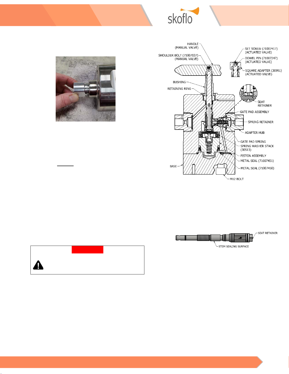
Figure 2 – SF10000HTVB Cross-Section..................................... 6
Figure 3 – Square Adapter Removal............................................ 6
Figure 4 – Gate Pad Assembly Removal .................................... 6
Figure 5 – Piston Assembly Removal .......................................... 7
Figure 6 – Stem Assembly Removal............................................. 7
Figure 7 – Stem Assembly Seals.................................................... 7
Figure 8 – Stem O-Ring Tool with Seals..................................... 7
Figure 9 – Piston Assembly.............................................................. 7
Figure 10 – Installing Piston Seal .................................................. 8
Figure 11 – Gate Pad Assembly Cross Section ........................ 8
Figure 12 – Stem Seal Cross Section............................................ 8
Figure 13 – Stem Seals ...................................................................... 8
Figure 14 – O-ring Press Tool......................................................... 9
Figure 15 – SF10000HTVB Cross-Section................................... 9
Figure 16 – Stem Sealing Surface ................................................. 9
Figure 17 – Spring Stack Arrangement.....................................10
Figure 18 – Gate View Through Gate Pad Hole.....................10
Figure 19 – SF10000HTVB with SF3 Actuator.........................11
Figure 20 – PDFM Connecting Tube..........................................11
Figure 21 – Troubleshooting.........................................................13
TABLE OF TABLES
Table 1 – Filter Specification ........................................................... 3
Table 2 – SF10000HTVB Spares Kit Part Numbers ................. 5
Table 3 – SF10000HTVB Rebuild Kit Number Guide ............. 5
Table 4 – SF10000HTVB Seal Kit Number Guide .................... 5
Table 5 – SF10000HTVB Stem Kit Number Guide .................. 5
Table 6 - Maintenance Tool Requirements............................... 5
Table 7 – Frequently Asked Questions .....................................12

Surface CIMV, Low Flow, HTV SF10000HTVB
Operations and Maintenance Instructions 2
ABOUT SKOFLO
Our experience and track record speak for itself. SkoFlo
has delivered over 20,000 valves since 1988. We are the
only company that proves our products by testing in
surface applications before deploying them subsea. The
result is that SkoFlo products have amassed over 25
million continuous operating hours. This level of
experience is unparalleled and provides the basis for being
the solution provider to our served market.
GENERAL INFORMATION
Product Overview
The SF10000HTVB is a pressure independent chemical
injection and metering valve (CIMV), used in the
petroleum industry to accurately control chemical injection
rates. The SF10000HTVB regulates flow to counter
pressure changes on the inlet and outlet of the unit. This is
referred to as “pressure independence”.
Pressure Independence
SkoFlo defines pressure independence as the percent (%)
of reading change for each 1,000 psi (69 bar) change in
supply or outlet pressure.
Pressure independence in the SF10000HTVB is a
completely mechanical process, requiring zero power.
The principle of pressure independence is that the valve
maintains a constant differential pressure (dP) across an
internal orifice (the ‘gate’), thus resulting in a constant flow
rate through that orifice.
The pressure that is generated by flow through the gate is
applied to either side of a spring balanced piston that
carries a regulating pin. The piston will travel to a position
where the spring force equals the pressure force.
Minimum Differential Pressure
For the SF10000HTVB to provide pressure independent
performance, a minimum differential pressure (min dP) is
required across the valve to allow the spring-balanced
piston to move to a truly balanced location.
In general, higher flows and/or viscosities require a higher
min dP across the valve. Refer to the product datasheet for
specific information.
Guidelines for Using this Manual
The following instructions are provided to ensure a safe
and proper installation and operation.
−Read all instructions prior to installation
and operation of this product.
−Follow all warning and caution notes.
−Install this product as specified in the
instructions provided by SkoFlo.
−Prior to use, educate personnel in the
proper installation, operation, and
maintenance of this product.
−Only use replacement parts specified by
SkoFlo.
Warning, Caution, Notice
Throughout this manual there are steps and procedures
which, if not followed, may result in a hazard. The
following flags are used to identify the level of potential
hazard.
! WARNING
WARNING IS USED TO INDICATE THE PRESENCE OF A
HAZARD WHICH CAN CAUSE SEVERE INJURY, DEATH, OR
SUBSTANTIAL PROPERTY DAMAGE IF THE WARNING IS
IGNORED.
! CAUTION
CAUTION IS USED TO INDICATE THE PRESENCE OF A
HAZARD WHICH CAN CAUSE INJURY OR PROPERTY
DAMAGE IF THE WARNING IS IGNORED.
! NOTICE
NOTICE IS USED TO NOTIFY PEOPLE OF INSTALLATION,
OPERATION, OR MAINTENANCE INFORMATION,
WHICH IS IMPORTANT BUT NOT HAZARD RELATED.
Abbreviations and Acronyms
CIMV Chemical Injection and Metering Valve
dP Differential Pressure
GA General Arrangement
GPD Gallons Per Day
HTV High Turn-Down Valve
LPH Liters Per Hour
SHCS Socket Head Cap Screw
psi Pounds per Square Inch

Surface CIMV, Low Flow, HTV SF10000HTVB
Operations and Maintenance Instructions 3
HYDRAULIC RATINGS
! WARNING
REFER TO THE GENERAL SECTION OF THE PRODUCT
DATASHEET FOR DESIGN PRESSURE DETAILS.
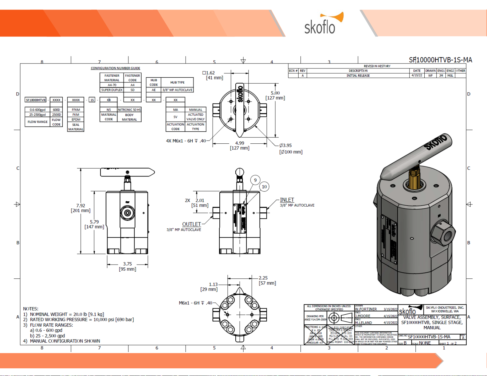
Max Working Pressure: 10,000 psi (689 bar)
Hydro-Pressure: 15,000 psi (1,034 bar)
Flow Ranges:
−0.6 to 600 GPD (0.09 to 95 LPH)
−25 to 2500 GPD (3.9 to 394 LPH)
Min Differential Pressure (DP) for Max Rated Flow: 300 psi*
* Lower flow rates require a lower DP
STORAGE
The SF10000HTVB should be stored in a shelter and be
protected from moisture and particulates. Storage
temperatures shall be between –50°F and 158°F (–45°C
and 70°C).
Any open hydraulic connections will be furnished with
plastic blanking plugs.
It is important not to store the SF10000HTVB with
production chemicals in the unit. These chemicals can
settle, possibly resulting in damage to the unit. SkoFlo
recommends that the valve be stored with a mixture of
glycol in water as the preservation fluid.
INSTALLATION
! WARNING
CHEMICAL COMPATIBILITY SHALL BE DONE AND CHECKED
BEFORE USE, EXCEPT FOR MEG AND WATER MIXTURES.
! WARNING
THE SF10000HTVB SHALL NOT BE INSTALLED SUBSEA.
1. Mounting
The SF10000HTVB can be panel or base mounted in any
orientation. See Appendix B for more details.
If panel mounting, unscrew the handle fastener with a
2mm Allen wrench and remove the handle. Mount the
valve, then replace the handle and tighten the fastener in
place.
2. Hydraulic Installation
Install the SF10000HTVB so that the flow is in the proper
direction. The IN (inlet) and OUT (outlet) connections are
marked respectively. See Appendix B for details.
Install an inline filter upstream of the SF10000HTVB.
Clean chemicals and proper filtering are very
important. Omitting the filter can cause the valve to
become plugged.
Table 1 lists the filter requirements for the various flow
ranges. Note: if coarser filters are used, the adjustment
handle may need to be periodically opened to flush out
any debris.
Table 1 – Filter Specification
Flow Range Filter Micron Size
0.6 to 10 GPD
40
10 to 700 GPD
80
> 700 GPD
200
A pulsation dampener is recommended to be installed on
the inlet header supplying the SF10000HTVB for improved
longevity and set point consistency. A bladder type
pulsation dampener is preferred over a piston type.
! NOTICE
THE SF10000HTVB REQUIRES A MINIMUM DIFFERENTIAL
PRESSURE ACROSS THE VALVE OF 300 PSI (20.7 BAR) TO
ACHIEVE FULL RATED FLOW.
! NOTICE
IT IS RECOMMENDED TO STORE THE ASSEMBLIES IN THE
SHIPPING CRATE, IF POSSIBLE.
Surface CIMV, Low Flow, HTV SF10000HTVB
Operations and Maintenance Instructions 4
Reactive dampeners that use baffles will do little to
dampen the pressure over the full flow range of the valve.
The SF10000HTVB is not a positive shut off device,
therefore, a valve on the inlet or outlet will be required to
meet shut off specifications. The preferred location of the
shut off valve is on the outlet of the SkoFlo valve to
minimize the shock to internal parts during start up.
A check valve shall be installed immediately downstream
of the SF10000HTVB (within 6 inches) to prevent damage
to the piston cup seal and to prevent well fluids entering
the valve. The 6-inch maximum is required to eliminate
stored pressure build up during startup. Check valve
cracking pressure is recommended to be under 10 psi to
enhance longevity of check valve seats.
An example of a typical chemical injection system is given
in Appendix A.
3. Start Up Procedures
3.1 Open the supply isolation valve to the SkoFlo
valve slowly (> 1 second). This will allow
pressures within the unit to equalize slowly,
the valve will stabilize quickly.
3.2 Turn the rate adjustment handle clockwise
until you are at the desired flow rate.
3.3 Always start at a flow rate above the desired
flow and decrease to the desired setting (turn
handle clockwise to decrease flow rate).
−For the most consistent set point results,
rotate handle ½ turn clockwise to reach
the set point.
3.4 The flow controller is now set, and further
adjustments are not required.
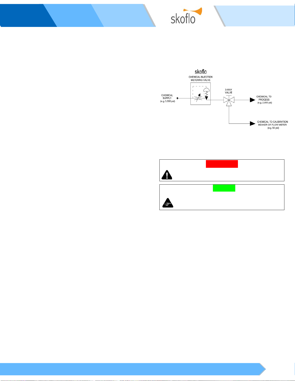
4. Adjustment and Calibration
The SF10000HTVB is a pressure independent flow control
device. Once the valve is set at a desired flow rate, that
flow rate is maintained even though the pressure
conditions upstream and/or downstream of the valve may
change considerably.
The flow rate can be set using an inline flow meter;
however, it must be capable of withstanding the process
pressure. Another method of calibrating the SF10000HTVB
is with a 3-way valve and a line to a calibration beaker.
Once the flow rate is set, the 3-way valve is switched to
direct the chemical to the process (see Figure 1).
Since the SkoFlo valve regulates the flow independent of
the pressure differential across it, the flow rate to the
process is the same as the flow rate set using the beaker.
Overall monitoring of the flow is done by taking inventory
of the usage from the supply tank.
Figure 1 – Valve Calibration Schematic
MAINTENANCE
! WARNING
ANY SERVICE REPAIR SHALL BE PERFORMED BY TRAINED
PERSONNEL.
! NOTICE
IF ANY ABNORMALITIES ARE FOUND THROUGHOUT THE
MAINTENANCE, PLEASE REPORT TO THE RESPECTIVE
ENGINEERS.

Surface CIMV, Low Flow, HTV SF10000HTVB
Operations and Maintenance Instructions 5
5. General
Spares kits available for typical maintenance items are
listed in Table 2. See Tables 3, 4, and 5 for part number
guides.
Table 2 – SF10000HTVB Spares Kit Part Numbers
ITEM PART NUMBER
Complete Rebuild Kit
31655-10-XXXX-XXXX-1S-XX-XX
Seal Kit
31664-10-XXXX-1S
Stem Assembly Kit
31625-10-XXXX-XXXX-XX-XX
Piston Assembly Kit
31623
Gate Pad
30512
Washer Spring Stack 30513
O-ring Installation Tool Kit
31624
Table 3 – SF10000HTVB Rebuild Kit Number Guide
2X
1S
31655 -10 -XXXX - - XX -N5 -XX
600D MA
2500D ACT
MANUAL
ACTUATED
ACTUATION
TYPE
CODE
0.6-600gpd
25-2500gpd
FLOW
RANGE
EPDM
CODE
SEAL
MATERIAL
XXXX
FFKM
FKM
DUAL
SINGLE
CODE
STA GE
SELECTION
Table 4 – SF10000HTVB Seal Kit Number Guide
2X DUAL
1S SINGLE
31664 -10 -XXXX -XX
FFKM
FKM
EPDM
SEAL
MATERIAL
CODE
STAGE
SELECTION
Table 5 – SF10000HTVB Stem Kit Number Guide
31625 -10 -XXXX --N5 -XX
600D MA
2500D ACT
EPDM
ACTUATION
TYPE
CODE
SEAL
MATERIAL
FLOW
RANGE
CODE
0.6-600gpd
FFKM
MANUAL
25-2500gpd
FKM
ACTUATED
XXXX
Table 6 - Maintenance Tool Requirements
Tools and Parts
Quantity
Vise
1
250 ft.lb [340 Nm] Torque wrench
1
50 ft.lb [68 Nm] Torque wrench 1
Socket extension
1
28mm socket
1
13mm socket
1
12mm socket
1
10mm Allen socket
1
Pliers
1
2mm Allen wrench
1
5mm Allen wrench (required for SF3 Actuator) 1
Brass Rod (3.5mm Diameter)
1
Hammer (required for SF3 Actuator)
1
9/16” wrench (required for SF3 Actuator with PDFM)
2
Circlip Pliers (.035” Tip Diameter) 1
HTVB O-Ring Installation Kit (P/N: 31624)
1
Brass Pick
1
Pick or small flat head electrical screwdriver
1
Parker Super Lube (or equivalent)
1
Dynatex Anti-Seize & Lubricating Compound (or
equivalent)
1
Molykote G-4700 Lithium/Moly Grease (or
equivalent)
1
Loctite 222 Low Strength Threadlocker (or equivalent)
1
Surface CIMV, Low Flow, HTV SF10000HTVB
Operations and Maintenance Instructions 6
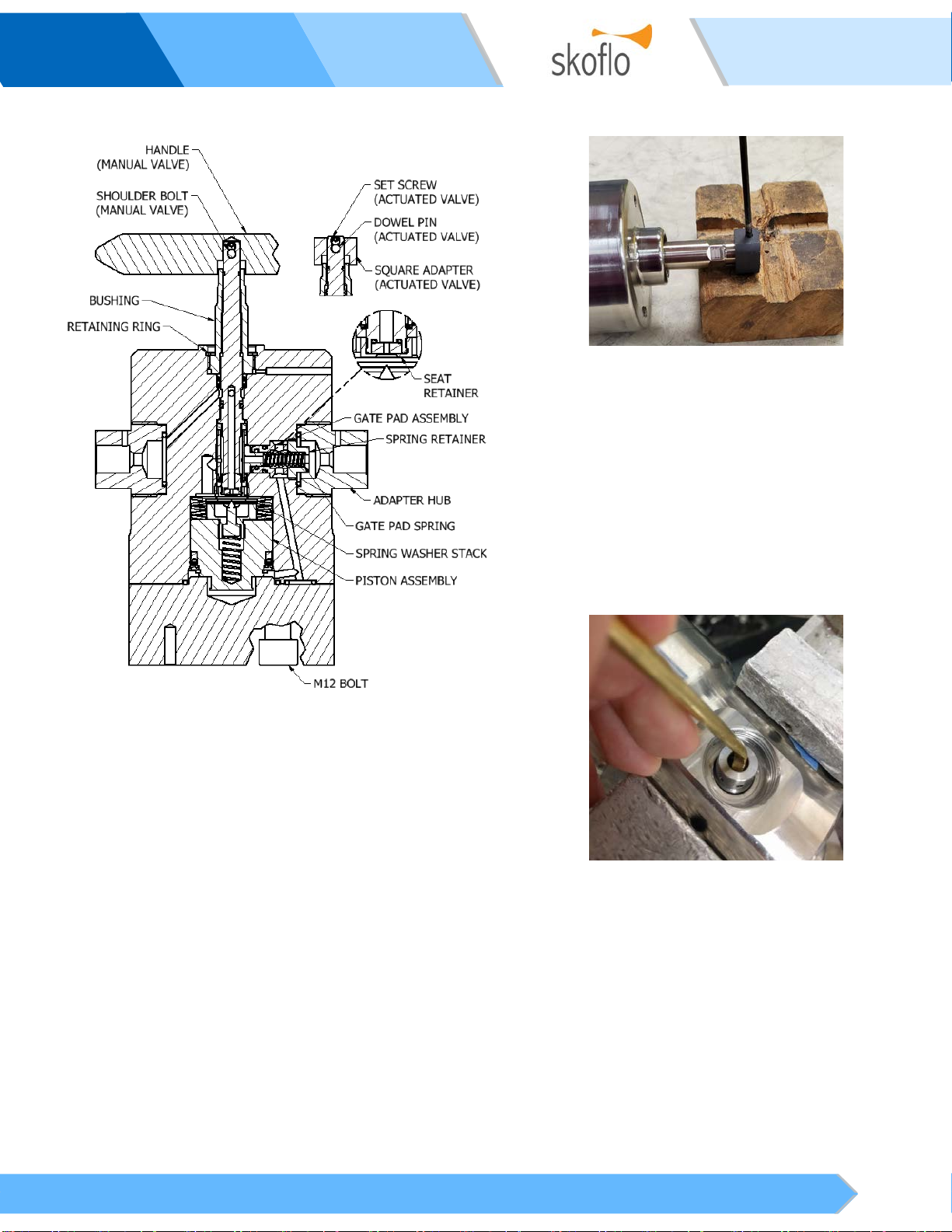
6. Disassembling the SF10000HTVB
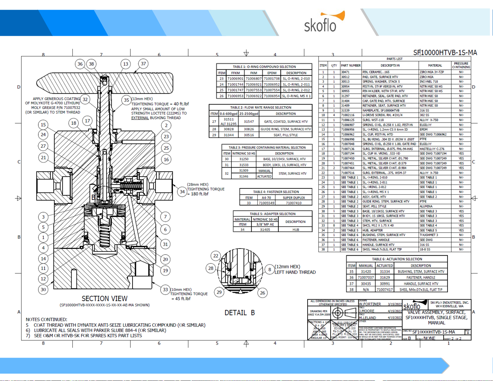
Figure 2– SF10000HTVB Cross-Section
6.1 Remove the valve from the system. If
applicable, see Section 13 for information on
unpairing the valve from an SF3 Actuator.
6.2 Rotate the handle clockwise until you reach
the bottom stop.
6.3 Remove the handle or square adapter
6.3.1 For Manual valves:
6.3.1.1 remove handle fastener –
2mm
Allen wrench
6.3.1.2 Remove handle.
6.3.2 For Actuated valves:
6.3.2.1 Remove set screw –
2mm Allen
wrench
.
6.3.2.2 Remove dowel pin. If necessary,
hold the square drive in a vise and
tap the dowel pin out –
3.5mm
dia rod, hammer
.
6.3.2.3 Remove the square adapter.
Figure 3 – Square Adapter Removal
6.4 Secure the valve in a vise with the inlet hub
facing up.
6.5 Unscrew the adapter hub (31405) –
28mm
socket
.
6.6 Unscrew the spring retainer (31404) –
12mm
socket
.
6.7 Remove the spring and gate pad assembly –
A brass rod can be used to aid pad assembly
removal.
Figure 4 – Gate Pad Assembly Removal
6.8 Resecure the valve in vise with the base
facing up.
6.9 Unscrew the 8x M12 bolts and remove the
base –
10mm Allen socket.
6.10 Remove the piston assembly and washer
springs. Set the piston down pin side up to
protect the tip of the pin –
pliers.
Surface CIMV, Low Flow, HTV SF10000HTVB
Operations and Maintenance Instructions 7
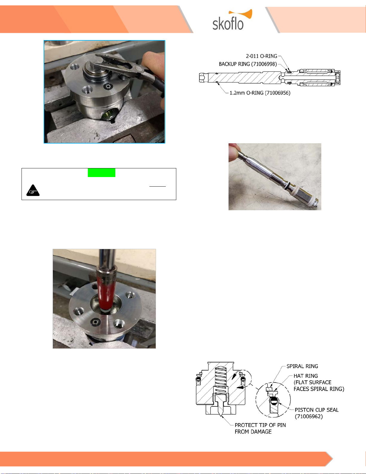
Figure 5 – Piston Assembly Removal
6.11 Place a 12mm socket over the seat retainer
(31409) and rotate counter-clockwise until
you can withdraw the old stem assembly from
the body –
12mm socket, socket extension
.
Figure 6 – Stem Assembly Removal
6.12 Remove valve from vise.
6.13 Remove the retaining ring (71007136) that
retains the stem bushing and discard –
Circlip
pliers (.035” Tip Diameter)
.
6.14 Resecure the valve in a vise with the stem
bushing facing out.
6.15 Unscrew the bushing from the body –
13mm
socket
.
7. Replacing the Stem Assembly Seals
Figure 7 – Stem Assembly Seals
7.1 Screw the O-ring installation tool onto the
stem as shown in Figure 8 –
PN 31479
(Actuated) or 31480 (Manual)
Figure 8 – Stem O-Ring Tool with Seals
7.2 Apply O-ring lube to the 2-011 O-ring.
7.3 Carefully slide the 2-011 O-ring over the stem
into the O-ring groove. Minimize stretching.
7.4 Carefully slide the backup ring (71006998)
over the stem into the O-ring groove.
Reform the backup ring into the groove as
needed.
7.5 Remove O-ring installation tool.
7.6 Apply O-ring lube to the 1.2mm O-ring
(71006956).
7.7 Slide the 1.2mm O-ring over the stem into
the O-ring groove.
8. Replacing the Piston Cup Seal
Figure 9 – Piston Assembly
! NOTICE
IT IS CRITICAL THAT THE GATE PAD IS REMOVED BEFORE
THE STEM. FAILURE TO DO SO WILL RESULT IN DAMAGE TO
THE STEM GUIDE RINGS.

Surface CIMV, Low Flow, HTV SF10000HTVB
Operations and Maintenance Instructions 8
8.1 Remove the spiral ring from the piston
assembly –
pick or small screwdriver
.
8.2 Remove the cup seal from the piston and
discard.
8.3 Apply O-ring lube to the new piston cup seal
(71006962)
8.4 Press the cup seal all the way on to the
piston. Protect the tip of the pin from
damage during cup seal installation by
placing a rag between the pin and the bench.
Note: the hat ring can be flipped over to aid
installation. See Figure 10.
Figure 10 – Installing Piston Seal
8.5 Orient the hat ring over so the flat side faces
the spiral ring. See Figure 9 for more details.
8.6 Install the spiral ring on the piston.
9. Replacing the Gate Pad and Gate Pad
Assembly Seals
Figure 11 – Gate Pad Assembly Cross Section
9.1 Remove the two O-rings from the gate pad
seal retainer and discard –
pick with bent tip
.
9.2 Install 2-010 O-ring into gate pad seal
retainer. This will be easier if you do not
lubricate it first.
9.3 Apply O-ring lube to the new 2-012 O-ring
and install on the gate pad seal retainer.
9.4 Apply O-ring lube to the gate pad shaft.
9.5 Insert the gate pad into the seal retainer.
9.6 Look inside seal retainer to verify O-ring was
not cut.
9.7 Remove the metal seal from the gate pad
plug and discard. Take care not to scratch the
sealing surface –
brass pick.
9.8 Apply O-ring lube to the new metal seal and
install in adapter hub.
10. Replacing Stem Seals
Figure 12 – Stem Seal Cross Section
10.1 Apply O-ring lube to stem seal tool. See
Figure 12
10.2 Insert stem seal tool fully into body.
10.3 Apply O-ring lube to a new chevron seal.
10.4 While holding stem seal tool in place, install a
new chevron seal (71007194) over the stem
seal tool. See Figures 12 and 13 for
orientation of the chevron seal.
Figure 13 – Stem Seals
Surface CIMV, Low Flow, HTV SF10000HTVB
Operations and Maintenance Instructions 9
10.5 Use the O-ring press tool to push seals fully
into gland. Screw in hand tight. See Figure 14
–
O-ring Press Tool (30643)
Figure 14 – O-ring Press Tool
10.6 Remove the O-ring press tool and check that
the chevron seal is correctly installed and not
cut.
10.7 Apply a small amount of low strength Loctite
to the external threads of the stem bushing.
10.8 Screw the stem bushing into the body.
Tighten hand tight. Note: the body must be
held in a horizontal position during this step
to allow the stem seal tool to move out of the
way as the bushing is screwed in.
10.9 Remove the stem seal tool.
10.10 Torque bushing to 40 ft.lbf [54 Nm] –
Torque
wrench, 13mm socket
.
10.11 Install the retaining ring (71007136) –
Circlip
Pliers
11. Valve Reassembly
Figure 15 – SF10000HTVB Cross-Section
11.1 Apply a generous coating of lithium grease to
the stem threads.
11.2 Apply O-ring lube to stem sealing surface.
See Figure 16.
Figure 16 – Stem Sealing Surface
11.3 Align gate profile with gate pad bore. Pushing
on the seat retainer, insert stem fully into
body.
11.4 Screw stem clockwise via seat retainer until
you reach the top stop. Once the handle hole
emerges from the bushing you can use a rod
through the handle hole to finish screwing in
the stem –
12mm socket, ø3.5mm rod
.
11.5 As the gate becomes visible in the gate pad
bore, align the gate profile with the gate pad
bore; use your thumb to keep it aligned as
you screw in the stem.
! WARNING
THE RETAINING RING MUST BE REINSTALLED TO
PREVENT THE STEM BUSHING FROM BACKING OUT,
WHICH COULD LEAD TO A HIGH-PRESSURE LEAK.

Surface CIMV, Low Flow, HTV SF10000HTVB
Operations and Maintenance Instructions 10
11.6 Verify that the gate profile is visible in the
gate pad bore and the gate guide ring is not
visible. Note: ceramic gate does not have a
top guide ring.
11.7 Place the valve in a bench vise stem facing
down.
11.8 Stack the spring washers, alternating dish up
and dish down. See Figure 17.
Figure 17 – Spring Stack Arrangement
11.9 Insert this stack into the valve body. The
outside edge must be facing down into the
body. See Figure 13.
11.10 Apply O-ring lube to the piston cup seal.
11.11 Insert the piston subassembly into the body,
pin side down. Press down on the piston with
the heel of your hand until the piston
contacts the springs.
11.12 Remove the metal seals from the bottom of
body and discard. Take care not to scratch
the sealing surface –
brass pick
.
11.13 Apply O-ring lube to the new metal seals and
install in the metal seal glands in the bottom
of the body.
11.14 Place the base onto the valve.
11.15 Apply anti-seize to the 8X M12 socket head
cap screws (SHCS) and install in the base.
11.16 Gradually torque the 8 fasteners in a star
pattern (in opposite pairs). It may take a
couple of passes to compress the metal seal
spring. –
10mm T handle hex key
11.17 Tighten SHCS in opposite pairs. Torque to 40
ft.lbf [54 Nm]. –
10mm hex key, torque
wrench
11.18 Double check all the fasteners are torqued
correctly by working clockwise through all 8. –
10mm hex key, torque wrench
11.19 Verify that the gate profile is visible in the
gate pad bore and the gate guide ring is not
visible (if applicable).
Figure 18 – Gate View Through
Gate Pad Hole
11.20 Secure the body in a bench vise with gate pad
bore facing up.
11.21 Insert gate pad subassembly into gate pad
bore, gate pad first.
11.22 Insert gate pad coil spring.
11.23 Screw in spring retainer –
12mm socket
.
11.24 Coat adapter hub threads with anti-seize.
11.25 Install adapter hub and torque to 180 ft.lbf
[244 Nm]. –
28mm hex, Torque Wrench
12. Handle Installation
12.1 Manual Valve
12.1.1 Place handle on stem and align the holes.
12.1.2 Insert shoulder bolt and tighten, be
careful not to shear the hex –
2mm hex
key.
12.2 Actuated Valve
12.2.1 Place square drive adapter on stem,
aligning holes.
12.2.2 Insert dowel pin into hole– ø
3.5mm rod,
hammer
.
12.2.3 Center dowel pin in square drive –
ø
3.5mm rod, hammer
.
12.2.4 Insert SHSS into end of stem and tighten
–
2mm hex key.
Surface CIMV, Low Flow, HTV SF10000HTVB
Operations and Maintenance Instructions 11
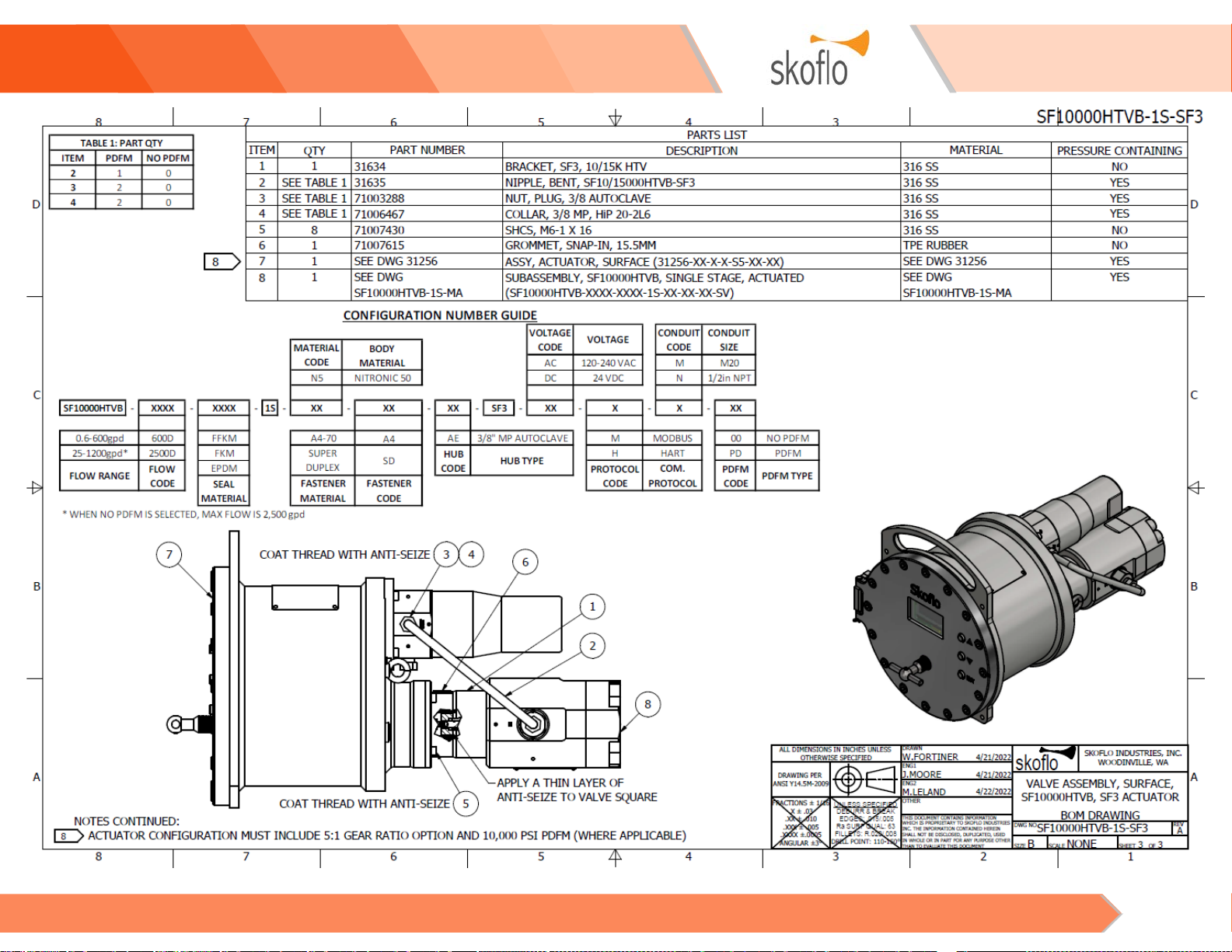
13. Disconnecting Valve From the SF3 Actuator
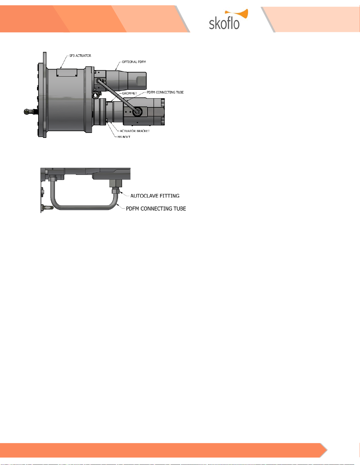
Figure 19 – SF10000HTVB with SF3 Actuator
13.1 If unit does not have a PDFM skip to step 13.5
Figure 20 – PDFM Connecting Tube
13.2 Unscrew the nut from each fitting –
5/8”
wrench.
13.3 Pull the tube out straight out from the
fittings.
13.4 Note the orientation of the actuator bracket
grommet to the SF3 Actuator and valve for
reference when reassembling.
13.5 Unscrew the 4X M6 bolts attaching the
actuator bracket to the SF3 Actuator.
13.6 Pull Disconnect the valve from the actuator.
13.7 Unscrew the 4X M6 bolts attaching the
actuator bracket to the SF10000HTVB.
13.8 Remove the bracket from the valve.
14. Reconnecting the SF10000HTVB to the SF3
Actuator
14.1 Apply a thin layer of anti-seize to the valve
square.
14.2 Remove the grommet from the actuator
bracket.
14.3 Apply anti-seize to 8X M6 bolts.
14.4 Orient the valve and actuator bracket as they
were prior to disassembly.
14.5 Insert 4X M6 SHCS in the bracket holes.
14.6 Tighten fasteners in opposite pairs –
5mm
hex key.
14.7 With the SF10000HTVB and actuator bracket
oriented as they were prior to disassembly,
align the square drive with the actuator drive
shaft. Rotate valve as necessary. Note: the
square drive can be viewed through the
grommet hole.
14.8 Slide the square drive into the drive shaft.
14.9 Realign the fastener holes.
14.10 Insert 4X M6 SHCS into the bracket.
14.11 Tighten fasteners in opposite pairs –
5mm
hex key.
14.12 Install the grommet in actuator bracket.
14.13 Reinsert the PDFM connecting tube to the
fittings in the valve and PDFM. Note: the
shorter end of the tube goes to the valve.
14.14 Tighten the autoclave nuts –
5/8” wrench.
14.15 After reconnecting the valve to the SF3
actuator, the actuator must be recalibrated.
See the appropriate SF3 Actuator and PDFM
user guide for more details.

Surface CIMV, Low Flow, HTV SF10000HTVB
Operations and Maintenance Instructions 12
FREQUENTLY ASKED QUESTIONS
Table 7 – Frequently Asked Questions
ALL CIMVs
Question
Answer
CIMV Shutoff
Ability
SkoFlo CIMVs are not shut off devices.
Separate isolation valves should be used for
shutting off the flow.
Protection
Against Reverse
Flow
A check valve shall be installed immediately
downstream of the valve (within 6 inches) to
prevent seal damage.
Minimum
Differential
Pressure to
Operate
See CIMV specification sheet that was supplied
with the CIMV to determine minimum required
pressure drop.
Excessive
Pressure Drop
For flows above 100 US gallons per day (15.8
LPH), pressure drops across the CIMV should
not exceed 3,000 psi (207bar) for extended
periods to avoid cavitation, which could lead
to erosion of the throttling components. As a
general rule, the outlet pressure must be
greater than or equal to the pressure drop to
avoid cavitation.
Fluid Cavitation
Fluid cavitation occurs primarily when CIMV
pressures (and secondarily fluid viscosity and
velocity) cause a drop below the fluid vapor
pressure. When the SkoFlo CIMV enters its
cavitation region, energy release from vapor
compression at the pin/seat interface may
cause premature wear.
Chemical
Filming
Historically, chemical filming has not been
experienced in SkoFlo HTD/HTV models.
Chemical filming is dependent on chemical
composition selection by the user. Injected
chemicals would need to have an affinity to
ceramic to film. Currently, there are no known
chemicals that have this affinity.
Blowout Proof
Stem
The stem design is blowout proof.
Surface CIMV, Low Flow, HTV SF10000HTVB
Operations and Maintenance Instructions 13
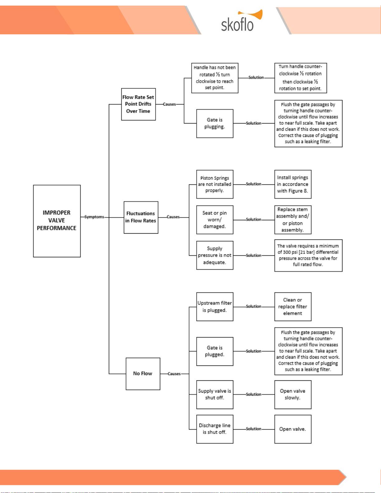
TROUBLESHOOTING
Figure 21 – Troubleshooting
Surface CIMV, Low Flow, HTV SF10000HTVB
Operations and Maintenance Instructions 14
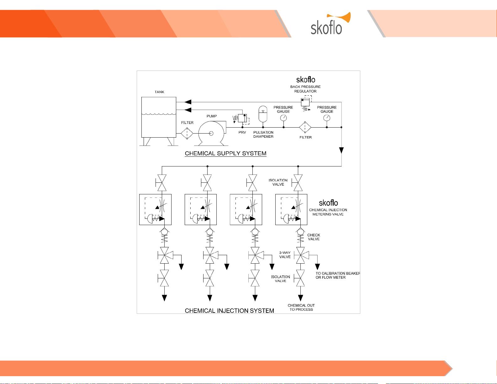
APPENDIX A–ATYPICAL CHEMICAL INJECTION SYSTEM
NOTES
Any number of injection points can be served by a single pump and header
system. The only limitation is the flow capability of the pump.
Check valve shall be installed within 6 inches of the SkoFlo CIMV.
Surface CIMV, Low Flow, HTV SF10000HTVB
Operations and Maintenance Instructions 15
APPENDIX B–SF10000HTVB GA AND BOM DRAWINGS
Surface CIMV, Low Flow, HTV SF10000HTVB
Operations and Maintenance Instructions 16

Surface CIMV, Low Flow, HTV SF10000HTVB
Operations and Maintenance Instructions 17

Surface CIMV, Low Flow, HTV SF10000HTVB
Operations and Maintenance Instructions 18
Surface CIMV, Low Flow, HTV SF10000HTVB
Operations and Maintenance Instructions 19
Table of contents
Other SkoFlo Industries Industrial Equipment manuals

Popular Industrial Equipment manuals by other brands


Stearns
Stearns 1-056-700 Series Installation and service instructions

Schaeffler
Schaeffler HEATER Series user manual

PHD
PHD GRL Series REPAIR PROCEDURES

Siemens
Siemens 3VA91 0JC1 Series operating instructions

Mapal
Mapal WTE Installation and operating instructions

Bosch
Bosch 0 986 613 461 Original instructions