Tidland C Series User manual

1
Tidland
Series 'C' Knifeholder
INSTALLATION MANUAL
Rigid Cartridge
Class I, II, III
Shear Slitting
Please read and understand all the
instructions before you install
the Tidland Series 'C' Knifeholder.
For information, contact:
Tidland Corporation
P.O. Box 1008
Camas, WA 98607
1-360-834-2345
1-800-426-1000 (USA)
PART NUMBER 52074
0
B
1 of 3 sections of Part Number 517333B

2

3
Table of Contents
Knifeholder Safety…………………………………………………………………………………. 4
Receiving and Unpacking………………………………………………………………………… 4
Knifeholder Components……………………………………………….………………………….5
A. Determine Web Path………………………………………………………………...6
1. Direction of Web…………………………………………………………………6
2. Type of Slitting………………………………………………………………….. 6
3. Select Contact Side……………………………………………………………..7
4. Select Cant Angle Key………………………………………………………….7
B. Prepare to Mount Guidebar…………………………………………………………8
1. Determine Space Requirements……………………………………………… 8
2. Determine Setback Distance (Tangent Shear Slitting only)……………….. 9
3. Determine Mounting Dimensions……………………………………………...10
a. Vertical Mounting Dimension……………………………………………...10
b. Horizontal Mounting Dimension…………………………………………..10
C. Mount Guidebar………………………………………………………………………11
D. Mount Knifeholder to Guidebar…………………………………….………………12
E. Install Pneumatic System………………………………………….……………….13

4
Knifeholder Safety
IMPORTANT!
§Read and understand all instructions before operating the knifeholder. Failure
to follow instructions may cause the knifeholder to function incorrectly and
cause serious injury.
§The Tidland Series 'C' Knifeholder is intended to be used to produce a slit
when operated with a driven anvil system, and there is no other intended
purpose.
§While operating the knifeholder, follow all existing plant safety instructions
and/or requirements.
§Always wear stainless steel protective gloves when changing or removing the
knife blade.
§Keep fingers clear of the blade edge at all times.
Receiving and Unpacking
§Handle and unpack the equipment carefully. Upon arrival, check the shipment
against the packing list.
§Any damage should be reported to the carrier at once.
§Equipment that will not be installed immediately should be stored in a clean,
dry location.
§Be careful to prevent moisture, dust, and dirt from accumulating in storage
and installation areas.
Sharp knives may cause
severe bodily injury.
Keep clear. Do not put hands in
machines. Keep hands away from
knife blades at all times.
Compliance with Federal, State, and
Local safety regulations is your
responsibility. Be familiar with them
and always work safely.
5
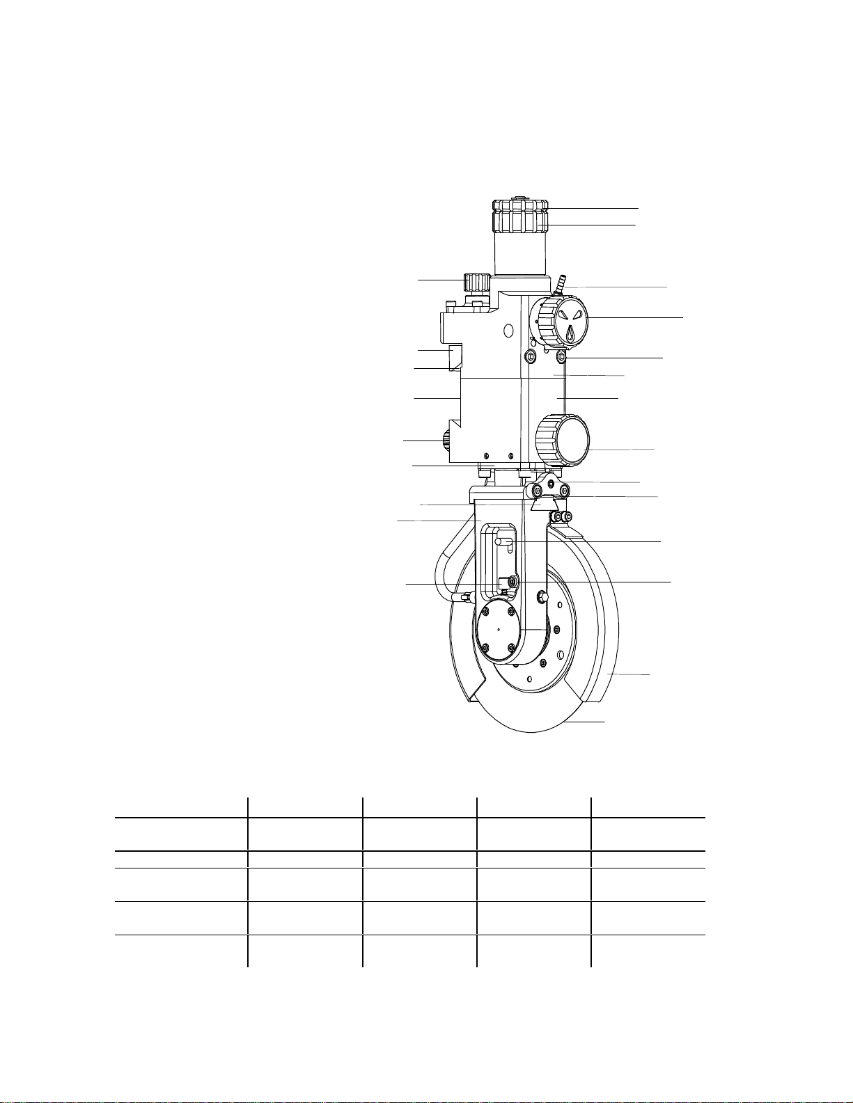
Knifeholder Components
Specifications
Tidland Series 'C' Knifeholder
Class I-25 Class I-33 Class II Class III
Knife Blade
Diameter
3.5" (90mm) 3.5" (90mm) 5.91" (150mm) 7.87" (200mm)
Minimum Slit 1" (25mm) 1.3" (33mm) 2" (50.80mm) 3" (76.20mm)
Typical Maximum
Speed*
3,500 fpm
(1,000 mpm)
3, 500 fpm
(1,000 mpm)
5,500 fpm
(1,677 mpm)
8,000 fpm
(2,439 mpm)
Recommended
Plant Air
Minimum 90 psi
(6.2 bar)
Minimum 90 psi
(6.2 bar)
Minimum 90 psi
(6.2 bar)
Minimum 90 psi
(6.2 bar)
Recommended
Operating Air
60-75 psi
(4.1-5.2 bar)
60-75 psi
(4.1-5.2 bar)
60-75 psi
(4.1-5.2 bar)
60-75 psi
(4.1-5.2 bar)
*Note: Actual speed is dependent on application and material
22
15
14
5
13
6
7
8
12
11
10
9
18
17
1
2
3
16
4
21
20
19
23
1. Manual Position Lock
2. Locking Gib
3. Auto-Lock Brake Shoe
4. Dovetail Mount
5. Pinion Gear
6. Rod Guide Bushing
7. Cant Angle Key
8. Strut
9. Set Stop Pin
10. Knife Blade
11. Blade Guard
12. Blade Lock
13. Latch Pin
14. Socket Head Capscrew
15. Wedge Lock Screw
16. Traverse Knob
17. Main Body
18. Valve Body
19. Gib Mounting Screws
20. Function Control Knob
21. Hose Barb Fitting
22. Depth Adjustment Knob
23. Depth Adjustment Lock Nut
6
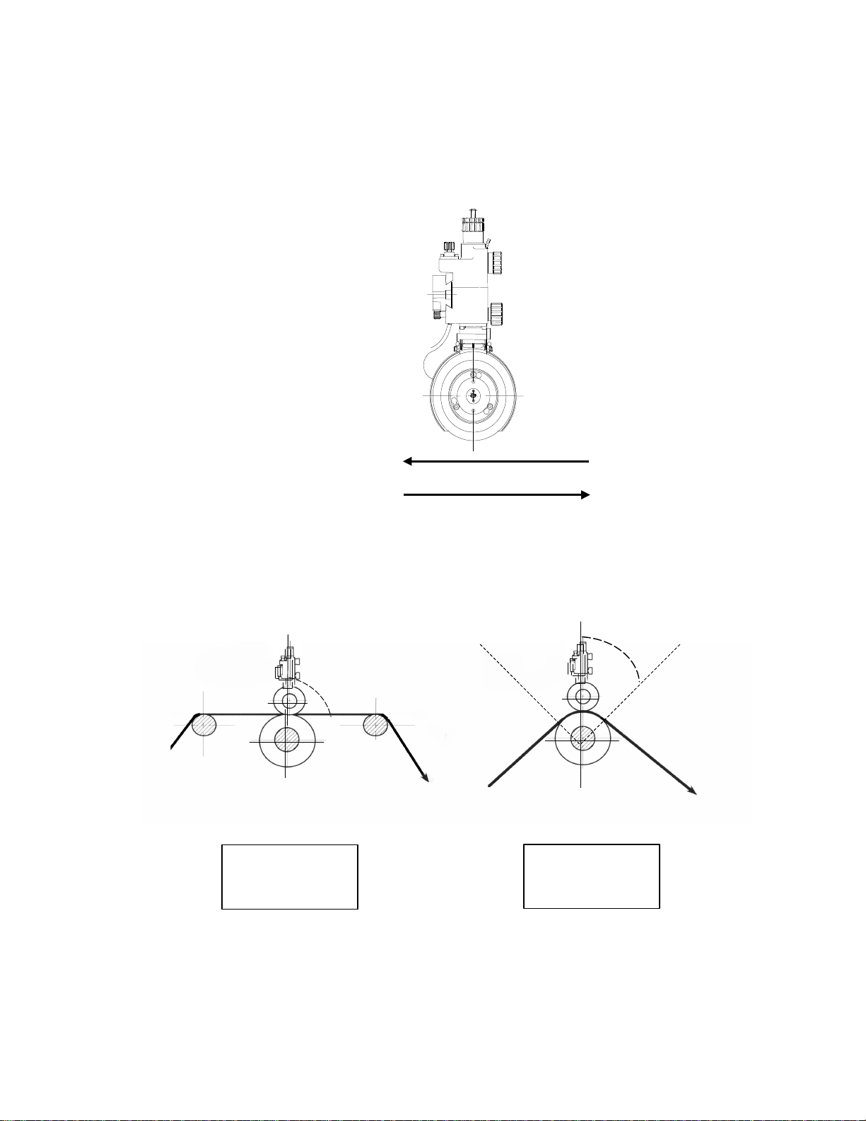
A. Determine Web Path
1. Direction of Web:
2. Type of Slitting:
Tangent
Wrap
OR
Knifeholder axis
should be 90° to
web path.
Knifeholder axis
should bisect
the wrap angle.
1/2 of wrap angle
90°
A
B

7
3. Select Contact Side:
4. Select Cant Angle Key:
The cant angle creates a precise shear cut point with the driven anvil
Web
Path
Contact
Side
Key
Required
ALR
ARL
BLL
BRR
See 'Changing the Cant Angle Key' in the Maintenance Manual.
L
Left side
R
Right side
8
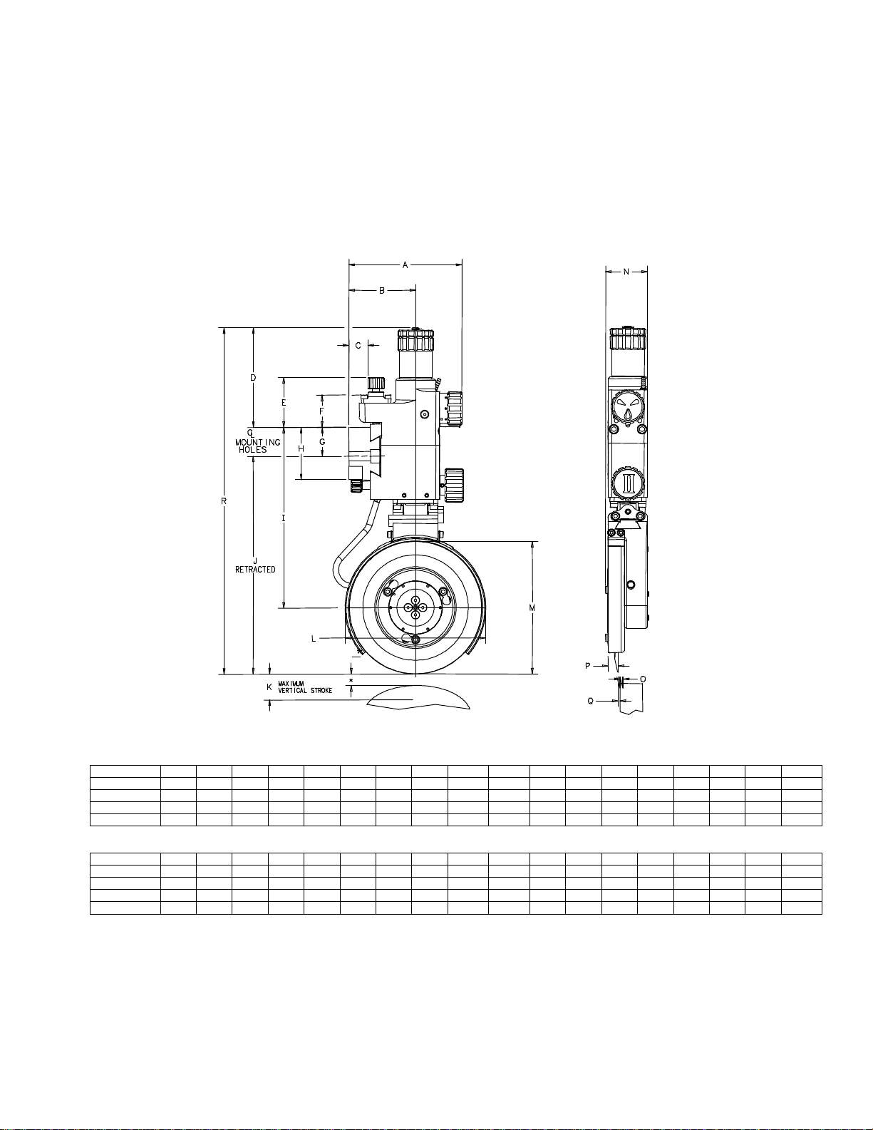
B. Prepare to Mount Guidebar
1. Determine Space Requirements
Inches ABCDEFGHIJKLMNOPQR
Class I-25 4.4 2.43 0.6 3.5 2.1 1.3 1.08 1.9 5.90 6.59 0.63 3.9 3.5 1.00 0.07 0.16 0.03 11.21
Class I-33 4.4 2.43 0.6 3.5 2.1 1.3 1.08 1.9 5.90 6.59 0.63 3.9 3.5 1.34 0.16 0.17 0.08 11.21
Class II 5.0 2.97 0.8 4.4 2.3 1.5 1.28 2.3 8.01 9.69 1.00 6.3 5.9 1.88 0.16 0.45 0.08 15.39
Class III 6.0 3.47 0.8 4.4 2.3 1.5 1.28 2.3 9.0211.67 1.00 8.3 7.9 2.75 0.24 0.97 0.12 17.37
Millimeters ABCDEFGHIJKLMNOPQR
Class I-25 112 61.7 15 90 53 33 27.4 48 149.9 167.4 16.0 99 90 25.4 1.8 4.1 0.8 284.6
Class I-33 112 61.7 15 90 53 33 27.4 48 149.9 167.4 16.0 99 90 34.0 4.1 4.3 2.0 284.6
Class II 127 75.4 20 112 58 38 32.5 58 203.5 246.1 25.4 160 150 47.8 4.1 11.4 2.0 390.9
Class III 152 88.1 20 112 58 38 32.5 58 229.1 296.4 25.4 211 200 70.0 6.1 24.6 3.0 441.2
Tidland Series 'C' Knifeholder Geometry
*Note: Reserve 1/2 of the total stroke for blade regrinding
*
Note: Dimensions are nominal and represent the average of assembled units. These are not the specifications of individual parts nor do they
reflect manufacturing tolerances.
9
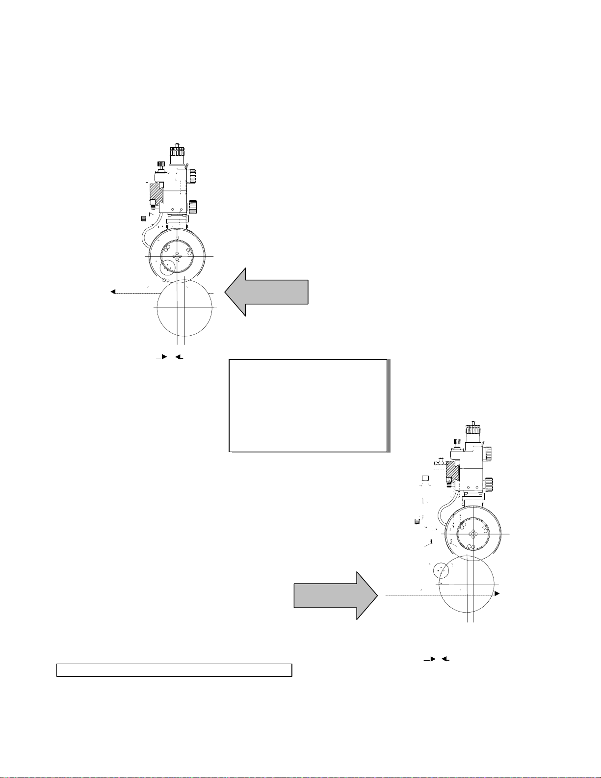
2. Determine Setback Distance (for Tangent Shear Slitting only)
"A" Web Path
"B" Web Path
Typical Setback for
Paper Based Products*:
Class I-25: 1/8" (3.18mm)
Class I-33: 1/8" (3.18mm)
Class II: 1/4" (6.35mm)
Class III: 3/8" (9.53mm)
Setback
Setback
* Other products may require different setbacks.
10
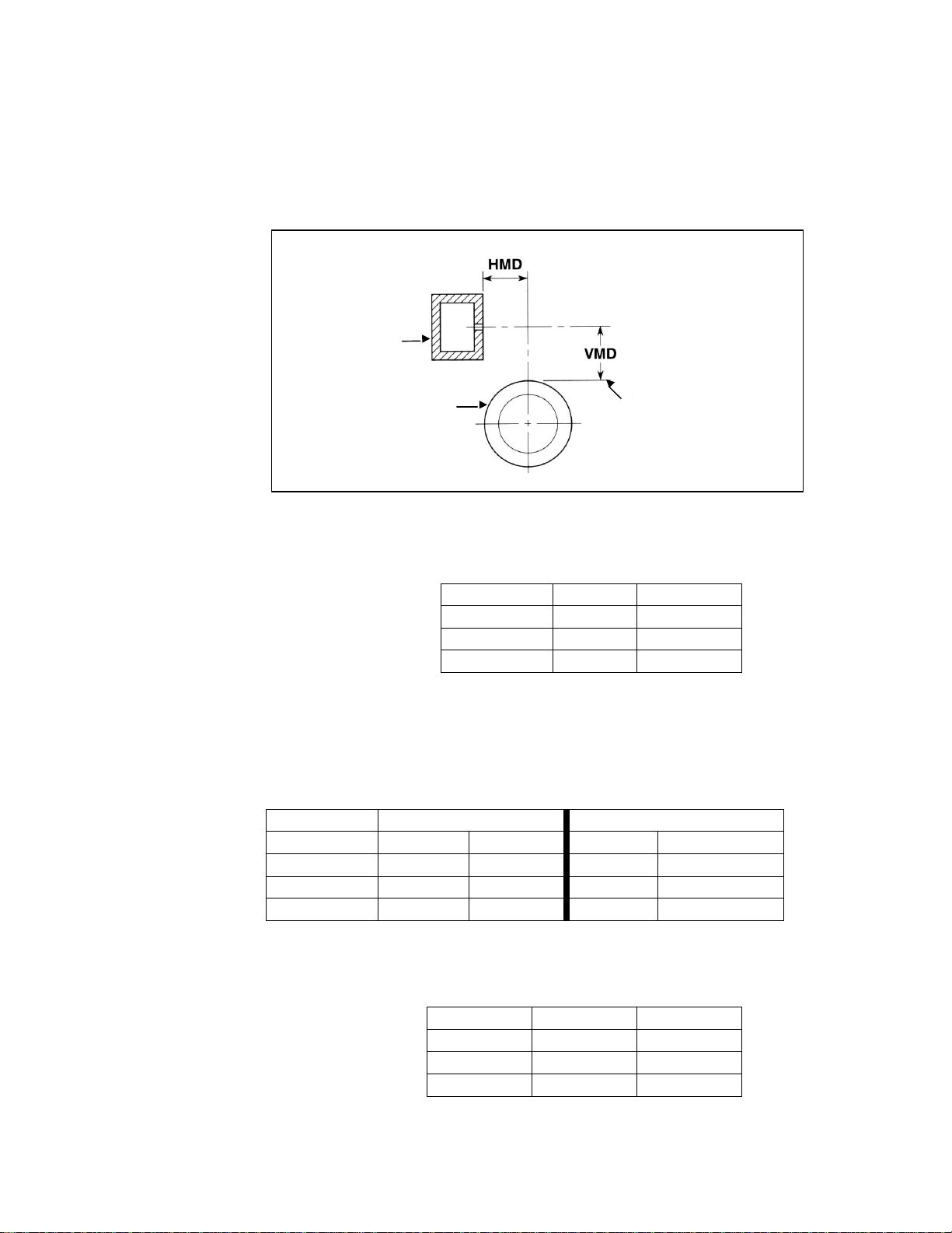
3. Determine Mounting Dimensions
a. Vertical Mounting Dimension (VMD)
Class I-25 6-29/32"
175.39mm
Class I-33 6-29/32"
175.39mm
Class II 10-3/16"
258.76mm
Class III 12-3/16"
309.56mm
b. Horizontal Mounting Dimension (HMD)
"A" Web Path "B" Web Path
Class I-25 2-9/16"65.09mm
2-5/16"58.74mm
Class I-33 2-9/16"65.09mm
2-5/16"58.74mm
Class II 3-7/32" 81.76mm
2-23/32"
69.06mm
Class III 3-27/32"
97.63mm
3-3/32" 78.58mm
Class I-25
2-7/16"61.72mm
Class I-33
2-7/16"61.72mm
Class II 2-31/32" 75.40mm
Class III 3-15/32" 88.10mm
Wrap Shear Slitting
"A" and "B" Web Paths
Tangent Shear Slitting
Tangent and Wrap Slitting
These dimensions reserve approximately 1/2 of knifeholder stroke for blade regrinding.
These dimensions will result in setbacks as listed in 'Determine Setback Distance'.
These dimensions provide
no
setback.
Anvil blade
Support beam
(Horizontal Mounting Dimension)
Parallel to web & tangent
to anvil blade
G
uidebar mounting holes
(Centerline)
(Vertical Mounting Dimension)

11
C. Mount Guidebar
1. Mark the mounting bolt center line on the support beam.
2. The guidebar must be straight within 0.010" (0.25mm) on a rigid and
vibration free support.
3. Measure the center to center distances between the mounting bolt
holes (A) on the guidebar and the overall length of the guidebar (B).
Note: Leave enough free space on each end of the support beam
for knifeholder removal.
Minimum Space Recommended
for Removal (Free Space)
Class I-25 2" (50.80mm)
Class I-33 2" (50.80mm)
Class II 3" (76.20mm)
Class III 4" (101.60mm)
4. Transfer the dimensions(A) on the support beam centerline.See note
in step 2; all mounting holes may not be equally spaced.
5. Center punch the mounting bolt pattern on the marked line.
6. Drill and tap the support beam for the mounting bolts.
7. Clamp the guidebar in place on the support beam.
8. Work from one end to the other installing the bolts until the guidebar is
securely fastened to the support beam.
Note: Make sure that the guidebar is aligned (parallel) with the
driven anvil.
Guidebar
B
Free Space
Note
:
The guidebar mounting bo
lt holes are pre
-
drilled
—
if applicable.
"
A
"
= 12"
(304.80mm). Mounting hole spacing near either end of guidebar may be less
than the standard 12" (304.80mm) spacing.
A

12
D. Mount Knifeholder to Guidebar
1. Turn the manual position lock knob counterclockwise to fully retract.
2. Make sure that the auto-lock brake shoe is fully retracted into the
locking gib.
3. Align the dovetail mount and pinion gear to the guidebar and gear rack.
4. Slide the knifeholder onto the guidebar from one end.
5. Turn the traverse knob to make sure that the knifeholder moves freely
on the guidebar.
6. Adjust the pinion gear clearance using the traverse setscrew. Keep in
mind that the gib brake will "pull" the pinion gear into the gear rack, so
leave enough clearance.
7. Tighten the manual position lock knob to secure the knifeholder in
position.
Note: Where end installation is not possible by sliding the knifeholder
onto the guidebar, the knifeholder can be mounted by removing
the locking gib.
a. Remove locking gib mounting screws located on the front of
the control body.
b. Remove locking gib.
c. Place knifeholder on guidebar.
d. Reinstall the locking gib without altering the setscrew setting.
e. Hold the knifeholder firmly against the locking gib while
alternately tightening the locking gib mounting screws.
Manual Position Lock Knob
Locking Gib
Traverse Knob
Guidebar
Pinion Gear
Auto-Lock Brake Shoe
Dovetail Mount
Locking Gib
Mounting Screws (2)
Gib Adjustment
Setscrews (2)
Traverse Setscrew (1)
Guidebar
Note:
If the knifeholder does not move freely on the guidebar, refer to step 1.
Impact to the knifeholder body should never be used to move the knifeholder.

13
E. Install Pneumatic System
§Tidland Corporation recommends the use of a pneumatic system to prevent
airborne oil or water from contaminating the knifeholders.
The pneumatic system (Part Number: 520984) includes:
§Recommended operating air pressure: 60-75 psi (4.1-5.2 bar).
This is a guideline for knifeholder setup; the actual air pressure is dependent
upon application and material.
§Clean, non-lubricated, dry air is required for optimum performance of the
Series 'C' Knifeholder.
§Before operating the knifeholder, make sure that the air lines from the air
manifold to the blade cartridge are securely connected.
A
B
C
D
A. 3/8" (9.52mm) supply air lines
B. 5 micron air filter/pressure regulator with gauge
(0-100 psi or 0-6.9 bar)
C. Coalescing filter
D. 3-way manual valve with muffler
E.
Quick exhaust valve with muffler
air manifold*
E
quick disconnect fitting*
*
The air manifold and quick disconnect fittings
are also available from Tidland.

14

15

16
In
the United States
In the United Kingdom
In Germany
Tidland products are
Tidland Corporation Tidland-Fife Tidland GmbH also manufactured in:
P.O. Box 1008 70-72, Manchester Road Siemensstrasse 13-15 Keene, NH U.S.A.
Camas, WA 98607 Denton, Manchester D-48683 Ahaus Sao Paulo, Brazil
U.S.A. UK M34 3PR Germany Sydney, Australia
Phone: 1-800-426-1000 Phone: 161-320-2000 Telefon: 02561-6880 Tokyo, Japan
1-360-834-2345 Fax: 161-320-4513 Fax: 02561-6495 Mumbai, India
Fax: 1-360-834-5865 Email: [email protected] Email: info@tidland.de
Web Site: www.tidland.com
© 2000 Tidland Corporation Rights reserved to amend technical details without notice 520740B of 517333B December 2000
Fife Corporation
Magnetic Power Systems, Inc.
Tidland Corporation
Table of contents
Other Tidland Industrial Equipment manuals


Popular Industrial Equipment manuals by other brands

3M
3M Flexiguard 8517762 User instruction manual

Sylvac
Sylvac D200S operating instructions

ITW Gema
ITW Gema EasySelect-Cup Operating instructions and spare parts list

turck
turck TN-IOL2 Series Instructions for use

Virutex
Virutex FC116U operating instructions

Somat
Somat SPC-60 Series Service training manual


