ADSI 9240 User manual


2
Table of Contents
1Introduction........................................................................................................................4
1.1 Description .........................................................................................................................4
1.2 Software Development Kit ................................................................................................4
1.3 Operating Modes................................................................................................................4
1.4 Manual Conventions ..........................................................................................................5
2Electrical Connections .......................................................................................................5
2.1 Connector Locations ..........................................................................................................5
2.2 Power Supply Connections................................................................................................6
2.3 Analog Signal Connections................................................................................................7
2.4 Digital Signal Connections ................................................................................................8
2.5 Preamplifier .......................................................................................................................9
3Stand-Alone Operation ....................................................................................................10
3.1 Configuration Settings .....................................................................................................10
3.2 The M Port .......................................................................................................................10
3.3 Other Signals....................................................................................................................11
4Computer-Driven Operation ............................................................................................12
4.1 C/D Port Signals ..............................................................................................................12
4.2 Command / Data Byte Transfer Cycle.............................................................................13
5Software Commands........................................................................................................14
5.1 Overview..........................................................................................................................14
5.2 Waveform Mode Commands...........................................................................................14
5.2.1 Analog Waveform Mode: ................................................................................................14
5.2.2 Digital Waveform Mode:.................................................................................................15
5.2.3 Chart Speed Commands...................................................................................................15
5.2.4 Channel Format and Enable Commands..........................................................................16
5.2.5 Grid Commands...............................................................................................................16
5.2.6 Print Chart Speed / Logo Commands ...............................................................................17
5.2.7 Annotation Commands ....................................................................................................17
5.2.8 Event Mark Commands ...................................................................................................19
5.2.9 Dither Commands ............................................................................................................20
5.3 Text Mode Commands.....................................................................................................20
5.4 Graphics Mode Commands..............................................................................................21
5.5 Miscellaneous Commands ...............................................................................................22
5.5.1 Reset Command...............................................................................................................22
5.5.2 Print Head Control Commands........................................................................................22
5.5.3 Step Motor Once Command ............................................................................................23
5.5.4 Self Test Command .........................................................................................................23
6Paper Loading ..................................................................................................................24
7Care of the Recorder ........................................................................................................24
8Specifications...................................................................................................................25
8.1 General.............................................................................................................................25
8.2 Waveform Mode ..............................................................................................................25
8.3 Text Mode........................................................................................................................26
8.4 Graphics Mode.................................................................................................................26
8.5 Digital Control Interface ..................................................................................................26
8.6 Environmental..................................................................................................................26
8.7 Reliability.........................................................................................................................26
Appendix A Using The 9240 with A PC...................................................................................27
A.1 Interface Cabling..............................................................................................................27

3
A.2 PC Parallel Printer Port Registers ....................................................................................28
A.3 Transferring Commands and Data to the 9240 ................................................................29
A.4 Programming Examples...................................................................................................30
Appendix B Software Command Summary ..............................................................................40
Appendix C Allen Datagraph Systems, Inc Warranty...............................................................41
Appendix D Shipping Claims I mp o r t a n t ...............................................................................42
Appendix E Firmware Part Numbers........................................................................................43
List of Examples
Example A-1 Analog Waveform Mode Programming .................................................................30
Example A-2 Digital Waveform Mode Programming..................................................................33
Example A-3 Vertical Text Mode Programming..........................................................................35
Example A-4 Horizontal Text Mode Programming .....................................................................36
Example A-5 Graphics Mode Programming ................................................................................38
List of Illustrations
Figure 2-1 9240 Controller Board Signal Connections Table ........................................................5
Figure 2-2 Typical Power Supply Control Circuit Using ~PSEN Control Signal ..........................7
Figure 2-3 Preamplifier Schematic ...............................................................................................10
Figure 4-1 C/D Port Signal Timing...............................................................................................13
Figure 5-1 Grid Pattern Examples ................................................................................................17
Figure 5-2 Annotation Segment Positions, 1 x 40 mm Channel Format ......................................18
Figure 5-3 Annotation Segment Position, 2 x 20 mm Channel Format........................................18
Figure 5-4 Event Mark Examples .................................................................................................20
Figure 5-5 Text Mode Character Orientation ...............................................................................21
Figure 5-6 Bit-Mapped Graphics Data Orientation ......................................................................22
Figure A-1 Interface Cable - 9240 to IBM PC Compatible Parallel Printer Port .........................28
Figure A-2 Command / Data Byte Transfer Flowchart ................................................................30
Figure A-3 Example A-1 Output - Analog Waveform Mode Programming ................................33
Figure A-4 Example A-2 Output - Digital Waveform Mode Programming.................................35
Figure A-5 Example A-3 Output - Vertical Text Mode Programming.........................................36
Figure A-6 Example A-4 Output - Horizontal Text Mode Programming.....................................38
Figure A-7 Example A-5 Output - Graphics Mode Programming................................................39
List of Tables
Table 2.1 Power Supply Connections.............................................................................................6
Table 2.2 Analog Signal Connections.............................................................................................8
Table 2.3: Digital Signal Connections ............................................................................................9
Table 3.3.1 M-Port Speed Selection P2 ........................................................................................11
Table 4.1 C/D Port Byte Transfers................................................................................................13
Table 5.1 Character Set.................................................................................................................19
Table A.1 IBM PC Parallel Port Bit Assignments For Programming 9240 .................................29
Table B.1 9240 Software Command Summary ............................................................................40

4
1 Introduction
1.1 Description
The Model 9240 is a two-channel 40 mm thermal strip-chart recorder module. Featuring microprocessor-based
electronics and thermal dot array print head, the 9240 can either be operated in stand-alone mode or it can be interfaced
to a host computer for additional flexibility. The versatility of the 9240 makes it the ideal chart recorder choice for a
variety of applications and systems.
The 9240 hardware consists of three basic modules:
•The paper transport consists of the mechanical housing, drive and print rollers, and a stepper motor drive train
for moving the chart paper at any of several calibrated speeds. A paper-out sensor is also provided.
•The 48 mm thermal print head is mounted on the top of the transport mechanism and contains an array of 384
thermal print elements.
•The microprocessor -based control electronics are located on a printed circuit board mounted on the
rear of the unit. The controller processes analog and/or digital signal information and controls the
operation of the paper transport and print head to produce waveform plots, text, or graphic images on the
chart.
1.2 Software Development Kit
The 9240 software development kit can be downloaded from the Allen Datagraph web site at
www.allendatagraph.com. Then click on Tech Support and choose the 9240 Recorder topic. The
development kit includes a driver and demonstration code that allows user level programs to write to the
parallel port of a PC from the Windows XP or Window 2000 operating system. The kit is written in
Delphi 6. If you want to make changes to the Delphi source code for the kit or use the Delphi driver
installation class, Delphi 6 is required. The kit uses a modified freeware driver developed by
http://www.beyondlogic.org/ using the PortTalk module. If you prefer to write in C you can modify the
driver installation software supplied by beyond logic to install the Allen Datagraph Port9240 driver by
changing the driver name in their code. The driver is compiled by the Windows XP driver development
kit. All source code is included in the kit.
1.3 Operating Modes
The 9240 features four distinct operating modes: analog waveform, digital waveform, text, and graphics. At
power-up, the recorder enters the analog waveform mode. In stand-alone applications, where the 9240 is not connected
to a host computer, only the analog waveform mode is available. For access to the other three operating
modes, the 9240 must be interfaced to a host computer.
ANALOG WAVEFORM MODE:
The 9240 reads the two analog signals that are input through the P6 connector, digitizes using the on-board A/D
converters, and plots the corresponding waveforms. The chart can be formatted as two separate 20 mm channels, with
one analog signal plotted in each channel, or both signals can be plotted together in a single 40 mm channel. Channel 0
includes an optional pre amplifier to allow voltage ranges other then 0 to 5 volts.
DIGITAL WAVEFORM MODE:
Digital data from the host computer is latched into the recorder's C/D Port (command/data interface port), and the
corresponding waveforms are then plotted.
TEXT MODE:
The 9240 receives ASCII characters from the host computer through the C/D Port and prints the
corresponding text in either horizontal or vertical format.
5
GRAPHICS MODE:
The recorder accepts "bit mapped" graphics data through the C/D Port and uses the bit patterns to address and control
the individual dot elements of the thermal print head. This mode can produce any desired graphics image or pattern on
the chart.
1.4 Manual Conventions
The ~ (tilde) character before an electronic signal name indicates that the signal is asserted when at the
LOW level. E.g. less then 0.8 volts.
The signal names which have a bar or over score are "true" when LOW.
A signal name with a bar over the top and the same named signal with a ~ prefix are the same signal.
~CMD/DATA Using a ~ in front of part of a name indicates the voltage level to select that name. In the case of ~CMD indicates a
low voltage is necessary to select CMD and high voltage is necessary to select DATA.
2 Electrical Connections
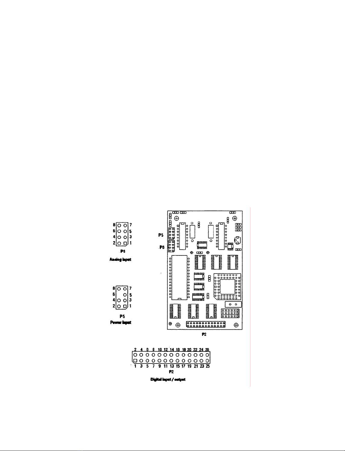
2.1 Connector Locations
All electrical connections to the 9240 are made through connectors P6, P5, and P2 on the controller circuit
board. These connectors carry analog signals, power supply connections, and digital interface signals respectively.
Figure 2.1 shows the location and orientation of these circuit board connectors on the Rev D CPU board. Connector
numbers and location differ slightly different in Rev B CPU boards.
Figure 2-1 9240 Controller Board Signal Connections Table

6
2.2 Power Supply Connections
Two separate DC power supply voltages are required for correct operation of the 9240:
A regulated 5-volt supply (Vlogic) is required for powering the controller logic and analog circuits.
A separate Vmotor/Vhead supply powers both the chart drive stepper motor and the thermal array print head. Several
different Vmotor/Vhead voltages are supported by different versions of the 9240; See Appendix E for the
Vmotor/Vhead voltage requirements (listed as "PRINTHEAD VOLTAGE") of your particular unit.
The power supplies are connected to connector P5 on the controller board as shown in Table 2.1.
Table 2.1 Power Supply Connections
P5 Connector Pinout Power Requirements
PIN # DESCRIPTION SUPPLY VOLTAGE RANGE WATTS
1 Vlogic Vlogic 5.0VDC ±10% 2 W
2 Vlogic GND
3 Vmotor/Vhead GND
4 Vmotor/Vhead GND
5 Vmotor
6 (key)
7 Vhead
8 Vhe ad
Vmotor = Vhead
(The same supply is usually
used for both head and
motor)
See Appendix E for nominal
Vmotor/Vhead voltage
12V nominal:
11-13.8 VDC
1 5 V nominal:
14 - 16 VDC
18V nominal:
17 -19 VDC
See Rev D note below
11-30V
Vmotor : 5W
Vhead : 64W
All black
printing. If only
192 pixels are
ever black then
32W
Note: The Vhead power supply should never be applied to the 9240 unless the Vlogic supply has been
switched ON and the microprocessor has had time to complete its reset cycle- This may be accomplished in
either of two ways. With either method, Vmotor is usually switched along with Vhead to save power.
An external timing circuit may be employed to ensure that the V. supply is not enabled until at least two seconds
after the Vlogic supply has stabilized to 5 volts. The external circuit must also insure that when the Vlogic
supply is switched off the Vhead supply is also immediately disabled
The ~PSEN signal line, located on the P2 digital signal connector, may be used as a control signal to activate an
external switch or relay to enable the Vhead supply. The PSEN signal line, described in futher detail in
Section 2.3, goes LOW under control of the 9240 microprocessor only when the Vhead supply is actually
required for chart motion or printing. ~PSEN stays HIGH at all other times when the Vmotor supply is powered
on. This is the preferred method of controlling Vhead. See Figure 2.2 for a typical power supply control circuit
using the ~PSEN signal line.
FAILURE TO FOLLOW THESE REQURIMENTS COULD PERMANENTLY DAMAGE THE PRINT HEAD
AND MAY VOID THE WARRANTY.
Rev D Board Note: On the revision D board a new power supply circuit has been added. This power supply
board converts the Vhead input voltage to 7.5 volts for the new head. As a result of the new power supply
board the voltage range requirements of the Vhead has been significantly loosened. If the 9240 you have, has
the new power supply board, then the Vhead/Vmotor voltage can be between 11V and 30V with the same
number of watts as specified in the table above. In addition the Vhead voltage is now controlled by the
~PSEN line which turns off the head voltage when the printer is not printing. As a result of this change there
is no longer a requirement to turn on the Vhead voltage after the Vlogic supply is turned on. They can be
powered on at the same time.
Note also that the Vlogic, and Vhead/Vmotor grounds must be tied together at the power supply.

7
Figure 2-2 Typical Power Supply Control Circuit Using ~PSEN Control Signal
2.3 Analog Signal Connections
In analog waveform mode, the 9240 scans the voltages of the two analog signals inputs and plots
the corresponding waveforms on the chart. The signals for channel 0 are fed into P6-1 (signal) and P6-2
(Gnd), while the signals for channel l are fed into P6-5 (signal) and P6-6 (Gnd). Each signal must be a positive voltage
with a range of 0 to 5 volts maximum, with 5 volts corresponding to full-scale amplitude of the output plot. Table 2.2
shows the connection of these signals to the analog signal input connector.
Note: Analog signal input lines are NOT over-voltage protected. Ensure that these lines do not experience
DC voltages greater than +5 VDC or less than 0 V with respect to GROUND.
FAILURE TO FOLLOW THESE REQUIREMENTS COULD PERMENANTELY DAMAGE THE
RECORDER AND MAY VOID THE WARRANTY.

8
Table 2.2 Analog Signal Connections
Connector P6
PIN # DESCRIPTION
1 Channel 0 input +
2 Channel 0 input -
3 Analog Ground
4 (Reserved)
5 Channel 1 input +
6 Channel 1 input -
7 Analog Ground
8 (Reserved)
2.4 Digital Signal Connections
Connector P2 carries all digital inputs and output signals between the 9240 and the external system. Table
2.3 lists the signals on the P2 connector along with a description of their use. All digital signals are TTL
compatible. All input lines have on-board resistors and are pulled HI if left unconnected.
Note: Digital signal lines are NOT over-voltage protected Ensure that these lines do not experience DC
voltages greater than +5.5 V or less than -0.7 V with respect to GROUND.
FAILURE TO FOLLOW THESE REQUIREMENTS COULD PERMANENTLY DAMAGE THE
RECORDER AND MAY VOID THE WARRANTY.
Four digital input signals (M0-M3) form the "M Port," used exclusively for controlling the 9240 in stand-
alone mode. The operation of the M Port is described in Section 3, Stand-Alone Operation.
Input signals D0-D7 form an 8-bit parallel bus. Along with the STR0BE, CMD / DATA, W/~A,
CHANNEL, and BUSY signals, this bus forms the "C/D Port" to provide a high-speed interface for
controlling the 9240 from a host computer. Section 4, "Interfacing the 9240 to a Computer," describes the
functions of these signals.
The remaining signals on connector are general-purpose control and status signals and may be used in
either stand-alone or computer-driven mode. These signals are described below:
~STEP (P2-10)
This input is provided as an external clock for the chart drive stepper motor. The motor speed selection must
be set to SINGLE STEP, either through the M Port (stand-alone mode) or by software command (computer-
driven mode). Once the SINGLE STEP speed has been selected, each negative-edge pulse of the STEP line will
advance the chart paper 1/18 mm. The maximum motor speed obtainable from the S T E P input is 25 mm per second,
corresponding to a maximum frequency of 450 Hz.
The ~STEP line can also be used to initiate the 9240's power-on self-test printout. To start a self-test,
connect the ~STEP line to logic ground when the power is off then apply power. When the self-test
printout begins, disconnect the ~STEP line from ground. See the Self Test Command description in Section
5.5.4 for a description of the self-test printout.
~PSEN (P2-19):
This output line is provided as a means for the 9240 to drive external circuitry for turning the Vhead/Vmotor
power supply on and off PSEN goes LOW just before the 9240 starts to print and then HIGH after
printing. It is recommended to use this line for efficient power consumption and head protection. See Section 2.1
for details.
~RESET (P2-21):
Bringing this input line LOW initiates a hardware reset of the 9240 and returns it to power-
up conditions. RESET shouldbeheldLOWaminimumof50milliseconds to insure that a reset cycle occurs.
~ALARM (P2-22):

9
This output signal goes LOW to indicate the presence of any of the following alarm conditions: paper
out, print head over-temperature, or self-test failure. Any communication with the 9240 when
ALARM is asserted will be lost. The recorder will halt all activity except monitoring of the alarm sensors
while the alarm condition persists.
Table 2.3: Digital Signal Connections
Connector. P2
PIN # SIGNAL NAME Direction FUNCTION. M Port (stand-alone)
mode
FUNCTION, C/D Port
(computer-driven) mode
1 ~STROBE Input No connection Latches D0-D7 &
~CMD/DATA into C/D Port
2-9 DO - D7 Input No connection 8-bit command / data bus (C/D
Port)
10 ~STEP Input External dock input for chart drive motor (also initiates power-on
self-test)
11 BUSY Output no connection Indicates C/D port busy status
12 CHANNEL Input Selects 1 x 40 mm or 2 x 20 mm
char format
Specifies channel for digital
waveform data
13 W/~A Input Triggers event mark Specifies data type: digital
waveform / other
14 ~CMD//DATA Input No connection Specifies content of D0-07:
command/ data
15 -18 MO - M3 Input Selects chart speed (M Port) Must be HIGH for C/D port
operation
19 ~PSEN Output Control signal for external switching of Vhead power supply
20 (Reserved) no connection
21 ~RESET Input Hardware reset of 9240
22 ~ALARM Output Indicates error condition: Paper out, print head over-temperature,
or self-test failure.
2 3 - 2 5 V l o g i c Gnd Ground reference for digital signal
26 (Reserved) No connection
2.5 Preamplifier
The schematic in figure 2.3 shows the configurable preamplifier only available on the Rev D 9240 CPU
board. The 9240 is normally shipped with the preamplifier disabled. E.g. JP2 and JP3 installed. To
configure the preamplifier you can use the preamp.xls worksheet that is included in the installation
directory of the software development kit. After installing Excel and the SDK from the start menu select
All Programs -> Allen Datagraph -< 9240 SDK -> Configure Gain of Preamplifier. Using the spreadsheet
you can set the minimum and maximum voltage levels to configure the preamp as either an attenuator or
an amplifier. To set the gain and offset of the amplifier follow the instructions on the preamp.xls. Install
the resistor in R7 (+ 4K) as calculated by the preamp.xls to set the gain range. With the power off with an
ohmmeter set to ohms Ωconnect to TP2 and JP1 and set the gain exactly using the gain pot. After setting
the gain, power up the 9240 with no analog input signal. Set DVM to DC volts (A V with a flat bar over
the top). Connect black to TP3 Gnd and red to TP1 and adjust the zero voltage to the value calculated by
preamp.xls. Move the jumper in JP2 to JP1. If very high gains are used you might have to separate the
grounds to get a clean signal by removing JP3.

10
Figure 2-3 Preamplifier Schematic
The analog and logic ground should then be connected in the customers power supply. A gain of 0.3 to 3
should be easy to configure. Higher gains may require an external preamplifier with isolated voltage
sources. If desired R7 can be chosen by the customer and Allen Datagraph will install this resistor at the
factory. Note: Ground bouncing caused by the print head turning on amplified by a large gain value
in the preamplifier will cause spikes on the waveform if a large (> 40) number of dots on the paper
are turned on simultaneously. If you need a large gain you will need to do one of the following:
Provide your own preamplifier or do not use a printed grid.
Use of the preamp will allow any range of analog signals in the range of –10V to 10V with a gain of 0.3 to
3 to be converted to the 0 to 5V range of the A to D converters on the board.
Note: the amplifier above inverts the analog signal input so the top of the range is mapped to 0V and the
bottom of the range is mapped to 5V. Software commands from the parallel port can be used to invert the
channel data back to normal. This feature can be defaulted on power up to either normal or invert status
E4H 22910 Invert Channel 0
E5H 23010 Normal Channel 0
3 Stand-Alone Operation
3.1 Configuration Settings
The 9240 is designed for quick setup of analog waveform mode recording without requiring connection to anexternal
computer. The chart format information is permanently set in the program ROM of the 9240's
microprocessor. The configuration sheet in Appendix E lists the power-up settings used in stand-alone mode for
your particular version of 9240 software. For an illustration of the grid patterns, see Figure 5.1.
The power-up settings are also printed out as part of the power-on self-test. For an explanation of running this self
test, refer to the description of the ~STEP signal in Section 2.3. Consult the factory if the self-test printout does not match
the configuration sheet or if your application requires custom settings.
3.2 The M Port
In stand-alone operating mode, the M Port, consisting of the four input signal lines M0-M3 (P2 pins 15-18),
is used to set the chart speed. Table 3.1 shows the M Port speed selections for the standard 9240 software
configuration. The configuration sheet lists the chart speeds for your unit, in order from speed 0 through 7.

11
Table 3.3.1 M-Port Speed Selection P2
M3
P2-18
M2
P2-17
M1
P2-16
M0
P2-15
SPEED
NUMBER
DEFAULT
SPEED*
L L L L 0 5 mm / sec
L L L H 1 10 mm / sec
L L H H 2 25 mm / sec
L L H L 3 50 mm / sec
L H L L 4 5 mm / min
L H L H 5 10 mm / min
L H H H 6 25 mm / min
L H H L 7 50 mm / min
H L L L Single Step (external dock)
H L L H
H L H L
H L H H
H H L L
H H L H
H H H L
Halt
H H H H Ignore M-Port
*See configuration sheet in Appendix E for speeds used in your version
The M Port inputs may be connected to TTL control signals or mechanically switched to Vlogic GROUND in the user's
system to control the 9240-chart speed. Internal pull-up resistors are provided on the M Port inputs, and the controller
scans and debounces the inputs continually to provide speed updates.
If M0-M3 are all HIGH, speed selection and other software commands from the C/D Port (host computer interface)
will be recognized; otherwise, the C/D Port is ignored. When the M Port inputs select the "HALT" speed, the ~PSEN
output (P2-19) goes HIGH to disable the Vhead/Vmotor power supply as described in Sections 2.1 and
2.2; several input combinations are provided for the "HALT" selection to simplify signal encoding. When the
"Single Step" speed is selected, the ~STEP input (P2-10) is enabled, allowing the chart to be driven from an external
clock See Section 2.3 for details.
3.3 Other Signals
In addition to the MPort, several other signals on the P2 digital I/O connector may be used to control the 9240
in stand-alone operation.. The operation of the general-purpose signals ~PSEN, ~STEP, ~ALARM, a nd ~ RESET
signals is described in Section 2.3. Two other signal lines usually associated with the C/D port have alternate functions
when used with the M Port in stand-alone mode:
CHANNEL (P2-12):
In stand-alone mode, this signal line selects the channel format used for the analog waveform recording. IfCHANNELis
HIGH or not connected, the 1 x 40 mm format is selected, with both analog signals plotted in a single 40 mm channel.
If CHANNEL is LOW, the analog data is plotted in two independent 20 mm channels, channel 0 data in the bottom
and channel 1 data in the top channel.
W/~A (P2-13):
When the 9240 is in stand-alone mode, pulsing the W/~A input LOW prints an event mark on the chart which
signifies some important event in the user's system. The event mark style is listed on the configuration sheet
in Appendix E. See Figure 5.2 for an illustration of the event mark styles. If the 2 x 20 mm chart format is
selected by bringing the CHANNEL line LOW, the W/~A line triggers event marks in both channels. The LOW-
going pulse on W/~A should be at least 1 millisecond long in order to be recognized.

12
4 Computer-Driven Operation
4.1 C/D Port Signals
For interfacing the 9240 to a host computer, a group of signals known as the C/D Port is provided on the P2 digital I/O
connector. Through this interface the host computer can set the 9240 to any of the four operating modes and can transfer
data for waveform mode annotation, digital waveform plotting, and text or graphics mode printing. The software
command set of the 9240 is described in Section 5.
The C/D P or t is a strobed 8-bit parallel input port of an IEEE-1284 parallel printer interface. For computer-driven
operation, the M Port pins (P3-15 through P3-18) should be set HIGH or left unconnected. The C/D Port signal
functions are defined as follows:
DO-D7 (P2-2 through P2-9):
These lines form the 8-bit input bus for transferring Command and Data bytes to the 9240. The least significant bit is
DO (P2-2), while D7 (P2-9) is the most significant bit of each byte.
~CMD/DATA ( P 2 - 1 4 ) :
This input specifies the content of the byte being sent on DO-D7. When ~CMD/DATA is LOW, a 9240
Command byte is being transferred. When ~CMD/DATA is HIGH, a Data byte is being sent, and the W/~A and
CHANNEL lines specify the type of Data transfer.
~STROBE (P2-1):
The host computer pulses this input line LOW to transfer Command or Data bytes to the chart recorder. The
falling edge of ~STROBE latches the contents of the D0-D7 and ~CMD/DATA lines into the 9240, and sets the BUSY
line HIGH.
W/~A (P2-13):
During Data byte transfers (~CMD/DATA = HIGH), the W/~A input line specifies the type of Data byte
being sent. When W/~A is HIGH, the Data byte contains digital waveform data to be plotted in the
channel specified by the CHANNEL input line. W/~A should be set LOW for all other types of Data transfers. These
include character data for text mode printing, bit-image data for graphics mode printing, and annotation text or other
command arguments for analog or digital waveform mode operation. The W/~A input has no meaning for
Command byte transfers (~CMD/DATA = LOW).
CHANNEL (P2 -1 2):
When Digital Waveform Mode Data bytes are sent to the 9240, the CHANNEL input selects the channel in which the
data is to be plotted, LOW for channel 0 data or HIGH for channel 1. CHANNEL has no meaning unless the
~CMD/DATA and W/~A inputs are both HIGH.
BUSY (P2-11):
This handshaking output goes HIGH when the C/D Port is busy. BUSY is set HIGH for each transfer by the
falling edge of ~STROBE and goes LOW again when the 9240 has processed the byte and is ready for another one.
Note that W/~A and CHANNEL are not latched, these lines must be stable before the start of ~STROBE and
remain so until BUSY goes LOW. The BUSY output is also set HIGH for the duration of the 9240 reset
cycle or while an ~ALARM condition exists (Section 2.3).
Table 4.1 contains a summary of the types of C/D Port byte transfers and the corresponding required states of the
~CMD/DATA, W/~A, and CHANNEL signals.
13
Table 4.1 C/D Port Byte Transfers
Transfer type (contents of DO-D7) ~CMD/DATA W / ~ A CHANNEL
Command LOW don't care don't care
Digital waveform data, channel 0 HIGH HIGH LOW
Digital waveform data, channel 1 HIGH HIGH HIGH
Non-waveform data (required by some commands.)
HIGH LOW (waveform modes)
don't care
(text/graphics modes)
don't care
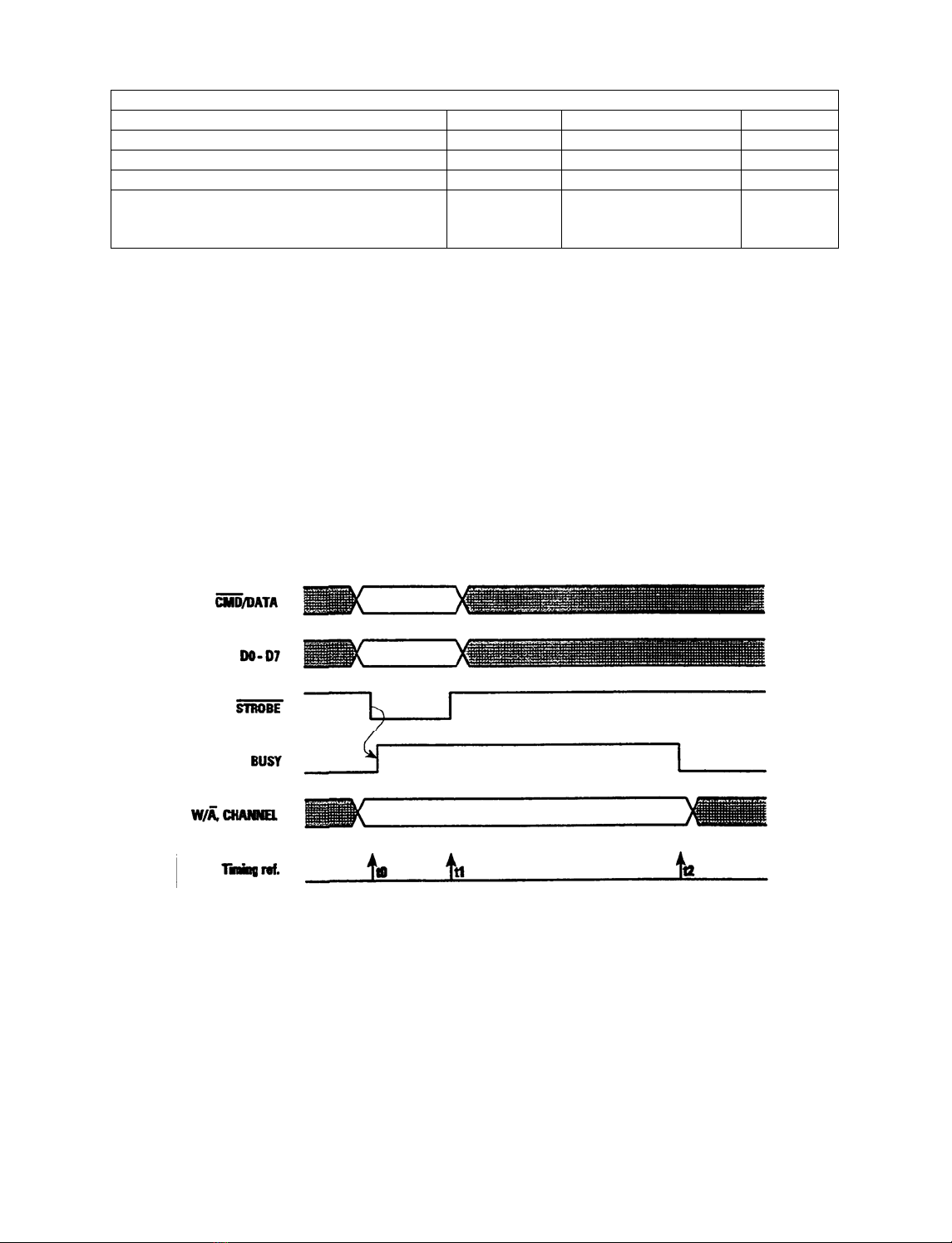
4.2 Command / Data Byte Transfer Cycle
The procedure for writing a Command or Data Byte to the 9240 is as follows. Figure 4.1 shows the timing of the C/D
Port signals for a byte transfer cycle.
Begin with the ~STOBE HIGH. Wait for the BUSY handshake line to go LOW before beginning each write
cycle.
Write the desired Command or Data byte information to the 8-bit bus D0-D7.
Write to the ~CMD/DATA, W/~A, and CHANNEL lines to set them the proper levels for the type of byte transfer
desired. (See Table 4.1).
While holding the D0-D7 bus, ~CMD/ DATA, W /~A, and CHANNEL lines stable, set the ~ST R O B E line
LOW, then HIGH again.
Continue to hold the ~CMD/DATA, W/~A, and CHANNEL lines stable. Wait for BUSY to go low
before transferring the next byte to the 9240.
Figure 4-1 C/D Port Signal Timing
Notes:
At ti me t0, the DO-D7 and ~CMD/DATA tines must be stable. These lines are latched and the BUSY line is
set HIGH by the falling edge of ~STROBE.
To prevent false triggering, DO-D7 and ~CMD/DATA should remain stable until after the end of the ~STROBE
pulse at t1.
The W/~A and CHANNEL lines are NOT latched and must be held stable at their respective levels before the
falling edge of ~STROBE at t0 until after the BUSY line goes L OW at time t2. No further communication can
reliably occur until after t2.

14
5 Software Commands
5.1 Overview
All four 9240 operating modes, Analog Waveform, Digital Waveform, Text, and Graphics, are supported by a set of
commands sent via the C/D Port computer interface. A single Command byte transfer enables most recorder
functions. Additional Data bytes are sent to the 9240 for plotting or printing in the Digital Waveform, Text, and
Graphics Modes, and also for chart annotation in both Analog and Digital Waveform Modes.
All software Command and Data transfers needed for 9240 operation are defined in this chapter. The discussion is
organized by operating mode. Analog and Digital Waveform Mode command descriptions are combined in a single
section, since these operate in essentially the same manner. Text Mode commands and Graphics Mode commands
are each treated in separate sections, and a section of miscellaneous 9240 command concludes the chapter.
5.2 Waveform Mode Commands
The recorder's two waveform plotting modes, Analog Waveform Mode and Digital Waveform Mode, use the same set
of software commands and operate identically except in the way that they obtain data for plotting. A curve-smoothing
algorithm plots the data traces in either mode.
The command set supports numerous features to control the appearance and content of the chart. The 9240
commands for Waveform Mode are categorized and described in order as follows:
•Waveform Mode Selection Commands
•Chart Speed Commands
•Channel Format and Enable Commands
•Grid Commands
•Print Chart Speed Commands
•Annotation Commands
•Annotation Font Commands
•Reverse Text Command
•Event Marker Commands
•Dither Command
5.2.1 Analog Waveform Mode:
To place 9240 into the Analog Waveform Mode, the following Command byte is sent: E7H 2 3 1 10 Enter Analog
Waveform Mode
The 9240 continually scans the analog signals from the P6 connector using the on-board A to D converters, and produces a
plot of the corresponding waveforms. This scanning process occurs automatically and requires no intervention by the
host computer. A signal voltage of 0 volts is plotted at the bottom of the corresponding channel on the chart. A voltage
of 5 volts is plotted at the top of the corresponding channel, an amplitude of 40 or 20mm, depending on the format
used. The external analog circuitry must scale the incoming signals as necessary to lie within the recorder's input voltage
range.
There are two curve-smoothing algorithms available:
Method 1: Min/Max value during time:
Method 2: Averaging of multiple readings for the A to D converter. The last (2, 4, 8 or 16) A to D
conversions are saved. When it is time to calculate a value to place on the recorder these values are averaged.
This has the effect of reducing the noise on the waveform by giving up some frequency response.

15
Selecting the Filter Length chooses the method. If filter length 0 is chosen the Min/Max method is used. If
Filter length of 2, 4, 8, or 16 is chosen the Averaging method is used.
E6+N 230 Set Analog Filter Length 0, 2, 4, 8, 16
5.2.2 Digital Waveform Mode:
The following Command byte sets the recorder into Digital Waveform Mode: E BH 23210 Enter Digital
Waveform mode
In this mode, waveform plots are generated directly from data bytes received from the C/D Port. Each byte is
interpreted as an unsigned integer ranging from 0 to 255 decimal (FFH), plotted as zero to full-scale on the chart.
Data bytes for Digital Waveform Mode plotting must be presented on the C/D Port with the ~CMD/DATA and
W/~A control lines both HIGH. The CHANNEL input directs plotting of the data to channel 0 of LOW or
channel 1 if HIGH. See section 4.1 for use of these control line. Digital waveform data sent in this
manner may be freely interspersed in the D/D port with other Command and Data bytes; digital waveform
data is placed immediately into the waveform data buffer when received, rather then being placed in the general-
purpose command queue. This permits Digital Waveform Mode data to be supplied to the 9240 at a constant
sample rate, without appreciable jitter. The SDK sets its priority level to Real Time to minimize the effects of
other things occurring while sending waveform data to the 9240 through the parallel port.
The maximum rate at which waveform data can be latched into the recorder is approximately 10k bytes per second
(5K bytes per channel if both channels are active). However, the 9240 requires only one data sample per channel between
motor steps to plot at its highest possible resolution. The chart is stepped in 1/18mm increments as points are plotted
on the chart paper. The number of steps per second is dependent on the chart speed and equals the speed divided by the step
size. For instance, at 25 mm/sec., the number of steps per second is 25 divided by 1/18, giving 450 steps/second. This
means that at 25 mm/sec., 450 bytes per second for each channel are required to plot at maximum resolution. If data is
supplied at a lower rate, the most-recently supplied data will be re-plotted as the chart advances, resulting in a "flat-line"
trace on the chart.
Digital Waveform Mode data may also be plotted on a non-real-time basis. Setting the chart speed to Single Step
mode, supplying the necessary data points for each waveform channel, and advancing the motor one step
after each data update, does this.Section 5.2.3 contains details of the commands to controlthe chart motor.
5.2.3 Chart Speed Commands
The following commands set the recorder chart speed. The speeds shown are those used for the standard version of the
9240 controller software. The configuration sheet in Appendix E lists the available speeds for your version, in order
from speed 0 through speed 7. The ~PSEN signal line, described in Section 2.3, goes LOW when the chart is running at
any of the selected speeds, and HIGH when the chart is stopped.
ECH 23610 Set Chart Speed 0: 5 mm/second*
EBH 23510 Set Chart Speed 1: 10 mm/second*
EAR 23410 Set Chart Speed 2: 25 mm/second*
E9H 23310 Set Chart Speed 3: 50 mm/second*
F0H 24010 Set Chart speed 4: 5 mm/minute*
EFH 23910 Set chart speed 5: 10 mm/minute*
EEH 23810 Set Chart Speed 6: 25 mm/minute*
EDH 23710 Set Chart Speed 7: 50 mm/minute*
FFH 25510 Stop chart
The chart drive stepper motor can also be controlled directly, either by an external clock signal (See the ~STEP signal
description in Section 2.3), or by software command. First the "Set Chart Speed: Single Step" command is given.
Then a series of "Step Motor Once" software commands or low-going pulses on the ~STEP input advance

16
the chart, 1/18 mm per step. In either waveform mode, all waveform data accumulated since the last step is plotted each
time a new step is made. When all steps have been given, the "Stop Chart" command given above should be sent to
de-activate the ~PSEN line.
F1H 24110 Set Chart Speed: Single Step
F5H 24510 Step Motor Once
5.2.4 Channel Format and Enable Commands
The chart may be formatted as a single 40 mm channel or two 20 mm channels. In the 1 x 40 mm chart format, either
or both waveform traces are plotted in a single 40 mm channel In the 2 x 20 mm format, a separate 20 mm channel is
provided for each waveform. Channel 0 data is plotted on the bottom and channel 1 data is plotted on the top. The
following commands establish the channel format used for plotting waveforms.
F3B 24310 Set Channel format: 1 x 40 mm
F2H 24210 Set Channel format: 2 x 20 mm
With either channel format, the following commands enable or disable the waveform traces individually. When a
channel is disabled, the corresponding analog or digital waveform data is ignored.
40H 6410 Channel 0 trace OFF
48H 7210, Channel 0 trace ON
41H 6510 Channel 1 trace OFF
49H 7310 Channel 1 trace ON
See the configuration sheet in Appendix E for the initial power-up settings for chart format and channel enable status.
5.2.5 Grid Commands
Grid Commands specify the chart background patterns for the reproduced waveforms. There are four grid
options available, the three patterns shown in Figure 5.1 plus a gird-off option. When the 2 x 20 mm channel format
is selected, grids may be specified independently for each channel. In the l x 40 mm format, the grid commands for either
channel control the single grid The grid pattern commands are as follows:
60H Grid, Channel 0, Pattern 0: OFF
61H Grid, Channel 1, Pattern 0: OFF
68H Grid, Channel 0, Pattern 1: 5 mm square
69H Grid, Channel 1, Pattern 1: 5 mm square
70H Grid, Channel 0, Pattern 2: 5 mm square, 1 mm divisions
71H Grid, Channel 1, Pattern 2: 5 mm square, l mm divisions
78H Grid, Channel 0, Pattern 3: 5 mm horizontal lines
79H Grid, Channel 1, Pattern 3: 5 mm horizontal lines

17
Figure 5-1 Grid Pattern Examples
See the configuration sheet in Appendix E for the initial power-up grid settings. If the power-up settings are for the
1 x 40 mm chart format, the grid pattern specified for channel 0 will control the single 40 mm g r i d
5.2.6 Print Chart Speed / Logo Commands
The 9240 can automatically print out the current chart speed whenever the waveform mode chart is running. A logo
consisting of a customer-defined text string can also be programmed into the 9240's ROM memory and printed out along
with the chart speed at periodic intervals. The chart speed / logo annotation is printed above is selected. Printout of the
chart speed and logo text may be individually turned on and off by the following software commands:
D1H 20910 Print Chart Speed OFF
D0H 20810 Print Chart Speed ON
D3H 21110 Print Logo OFF
D2H 21010 Print Logo ON
The interval at which the speed and logo printout is repeated can also be controlled by means of the following software
command The repeat distance is specified in centimeters by the value of the Data byte "Val",which may range from 5
to 255 decimal (05 to FFH). "Val" must be sent as anon-waveform Data byte transfer over the C/D Port, with the
~CMD/DATA line set HIGH and the W/~A line set LOW during the data transfer.
D4H+val 21210+val Set Speed/Logo Print Interval = val**
The configuration sheet in Appendix E lists the initial on-off setting for the initial print speed and logo and the initial
repeat interval. If there is no logo text programmed into your version of the 9240 ROM, there will be no entry for
logo on-off setting.
5.2.7 Annotation Commands
The 9240 can annotate the waveform with text strings received from the C/D Port as the chart is being plotted. Each
string may be up to 80 characters in length and is printed horizontally along the chart. Strings are positioned
vertically in any one of 45 locations, referenced from the bottom of the chart in 1 mm increments. Figures 5.2 and 5.3
show these locations in relation to the 1 x 40 mm and 2 x 20 mm chart formats, respectively.

18
Figure 5-2 Annotation Segment Positions, 1 x 40 mm Channel Format
The annotation commands have the following format:
00H + s t r i n g 010 +string Annotation @ 0 mmposition, t e x t = " s tr i n g "
through
2CH +string 4410 +string Annotation @ 44 mm position, text = "string"
T h e C ommand byte of each annotation command is sent in the normal manner on the C/D Port with the
~CMD/DATA line HIGH. This byte may range in value from 0 to 44 decimal (00H - 2CH). Its value
specifies the vertical position of the annotation text on the chart, ranging from 0 through 44mm.
Figure 5-3 Annotation Segment Position, 2 x 20 mm Channel Format
The annotation Command byte is followed by the argument "string," the text string to be printed. This is sent to the
C/D port as a series of Data bytes, with the ~CMD/DATAlineHIGH and the W/~A line LOW. The string may be up
to 80 characters in length. The text characters, any of the ASCII or special graphics characters shown in Table 5.1, are
placed into a holding buffer as they are received When the carriage return (CR =13 decimal or 0DH) or line
feed (LF =10 decimal or 0AH) character is received, the string buffer is printed at the specified position. If no CR or LF
character is sent, the string will be printed automatically when the buffer is filled with 80 characters.

19
Table 5.1 Character Set
The 9240 maintains four separate buffers for printing annotation, assigning annotation commands to these
buffers in a transparent round-robin fashion. Up to three completed annotation strings may be in the process of
printing while the fourth buffer is simultaneously receiving data from the host computer. If a fifth annotation command
is issued before the text from the first command has finished printing, the buffer containing the text from the first
command will be overwritten.
Note: In Digital Waveform Mode, waveform Data bytes may be interspersed freely with the character Data bytes
of annotation text. As each byte is received, the state of the W/~A line is used to make this distinction. This
mechanism prevents degradation of frequency response in the Digital Waveform Mode when using the
annotation function.
Waveform annotation may be printed in any of three high-resolution fonts, with character cell widths of 1, 2, or 3
mm. All character cells are nominally 3 mm high. The annotation font width may be changed by software command
The selected font will also be used for printing the chart speed and logo text, as described in Section 5.2.6. For reliable
results, thefont size should not bechanged while annotation text is being printed. The initial power-up font selection for
annotation printing is listed in Appendix E.
The annotation font selection commands are as follows:
DDH 22110 Set annotation font: 1 mm
DEH 22210 Set annotation font: 2 mm
DFH 22310 Set annotation font: 3 mm
The following Reverse Text Command reverses the image of all text characters. This command functions as a
toggle. Sent once, it changes all subsequent characters to print in reverse (white-on-black) mode; sent again, it
reverses to normal (white-on black) printing. This command may be used any time during recorder operation, and affects
Text Mode printing as well as all Waveform Mode text. On reset or power-up, the 9240 characters are set to normal
(black-on-white) printing. Note: Black backgrounds take more power for Vhead than white backgrounds.
D9 21710 Reverse Text: toggle ON/OFF
5.2.8 Event Mark Commands
Commands in this group highlight an area of interest on the cart Four styles of event markers can be generated by the
9240, as shown in Figure 5.4. In the 2 x 20 mm channel format, event marks can be independently generated for
each channel. In the l x 40 mm format, the event mark command for either channel may be used.

20
80H 12810 Event, Channel 0, Style 0: bottom tick
81H 12910 Event, Channel 1, Style 0: bottom tick
88H 13610 Event, Channel 0, Style 1: top tick
89H 13710 Event, Channel 1, Style 1: top tick
90H 14410 Event, channel 0, Style 2: center tick
91H 14510 Event, Channel 1, Style 2: center tick
98H 15210 Event, Channel 0, Style 3: across channel
99H 15310 Event, Channel 1, Style 3: across channel
Figure 5-4 Event Mark Examples
5.2.9 Dither Commands
The 9240 incorporates a feature known as dithering which helps prolong the life of the thermal array print
head. After every 255 centimeters of waveform mode plotting, the entire print pattern, including grids,
signal traces, annotation, and so on, is shifted upward by one chart position. After another 255 cm of
operation, the pattern is shifted back This procedure helps equalize wear on the individual print elements,
reducing stress on elements that lie on major grid divisions. Dithering operates only in the Analog and
Digital Waveform Modes, and can be turned off for applications that use paper with a pre-printed grid or
for printing with no grid. The following commands turn the dither feature on and off. Refer to the
configuration sheet in Appendix E to see if the dither is initially on or off for your version.
D6H 21410 Dither OFF
D5H 21310 Dither ON
5.3 Text Mode Commands
The Text Modes allow the 9240 to function as an alphanumeric printer, capable of printing the standard 96
ASCII character set along with 30 special graphics and math characters as shown in Table 5.1. Text can be
printed in 1 mm, 2 mm, or 3 mm wide fonts and oriented either vertically or horizontally on the chart. The
following commands select the 9240 Text Modes and fonts:
F8H 24810 Enter Vertical Text Mode, 1 mm font (48 columns across chart)
F7H 24710 Enter Vertical Text Mode, 2 mm font (24 columns across chart)
Table of contents
Popular Measuring Instrument manuals by other brands


Ionoval
Ionoval Mono operating instructions

FUTABA
FUTABA BR-4000 instruction manual

Endress+Hauser
Endress+Hauser PROFI BUS Proline Promag 53 PROFIBUS DP operating manual

IFM Electronic
IFM Electronic efector 300 SD9000 operating instructions

PCB Piezotronics
PCB Piezotronics ICP 602D11 operating guide

Utilitech
Utilitech CMG-102 Care and maintenance


