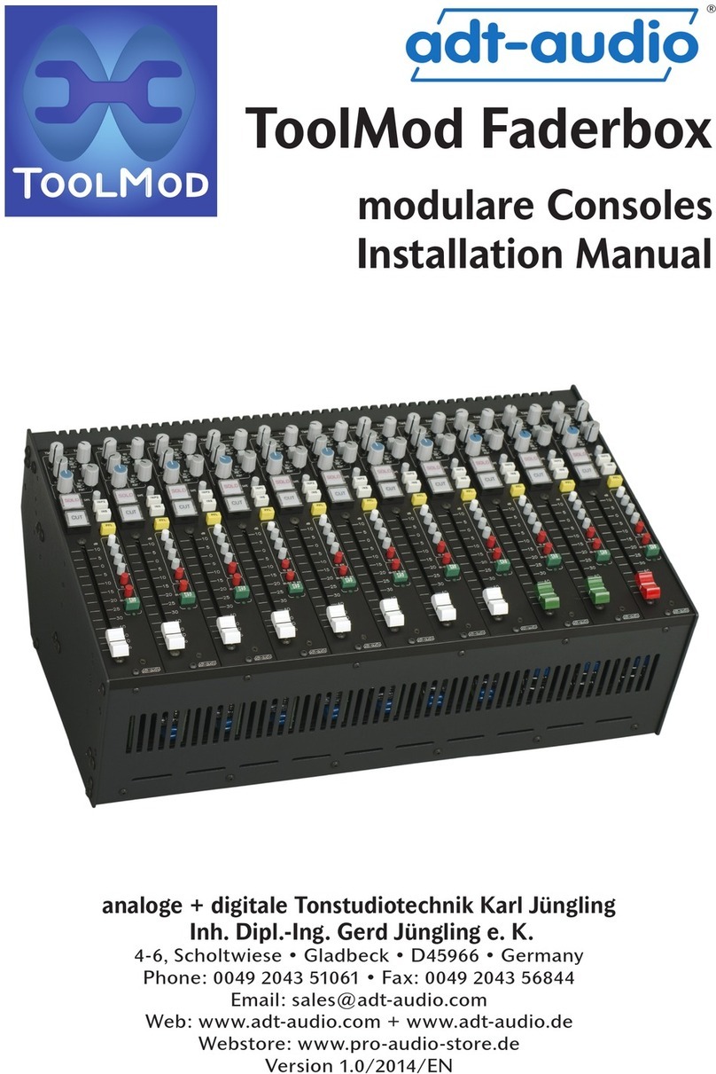
adt-audio 5MT User manual

Installation
Manual
Part II:
Connectors
Pinning Diagrams
Description of Connectors
for Consoles with D-Sub Connectors
analoge + digitale Tonstudiotechnik Karl Jüngling • Inh. Dipl.-Ing. Gerd Jüngling
4-6, Scholtwiese • Gladbeck • 45966 • NRW • Germany • Phone: 0049 2043 51061 • Fax: 0049 2043 56844
E-Mail: info@adt-audio.com • Internet: www.adt-audio.com www.broadcast-console.com
Version 1.6/07 • English
MT
MT
M
M
M
M
M
M
M
M
M
M

2
MT
MT
M
M
M
M
M
M
M
M
M
M
Summary
3. Connectors— 4
3.1 Technical data of Inputs and Outputs
— 4;
3.2 Connector Types
— 5;
3.3 Connector Panels
— 8;
4. Patch Bay— 20;

3
MT
MT
M
M
M
M
M
M
M
M
M
M
Preface
This manual contains all information that is necessary to prepare and plan
the installation of the mixing console and accessory components.
Please, read this manual carefully. We point out common mistakes and
problems that are connected with the installation and provide suggestions
to avoid such problems. You will save a lot of time and unnecessary start
up problems by investing a couple of hours in the reading of this manual.
The rst part of the manual contains everything about the power supply
units and crossover devices that are necessary for fail safe power supply
congurations and the implementation of the mains connections. Part 2
is about the audio installation. Besides detailed information about basic
principles of audio installation and the methods of grounding, this chapter
contains all pinning diagrams, the locations of the connectors, and a
detailed description of their functions. Part 3 contains general information
about the assembly of the console, environmental considerations, the
recommended maintenance, and a couple of remarks about the operation
of the console to ensure a long and problem free lifespan.
This manual concerns the stereo versions of the
5MT console system, Series S, Serie C and Series D
with D-Sub Connectors, Version V1.6/2007
Another manual is available for Consoles
with 30-Pin Siemens connector

4
MT
MT
M
M
M
M
M
M
M
M
M
M
3. Connectors
3.1 Technical data of Inputs and Outputs
The characteristic data of all audio inputs and outputs of the modules are
identical. Here is a listing of the basic data of the different types.
Level
The nominal level of the 5MT system is determined by the customer. It is
only xed by the adjustment of the system meters that can be set to any
level between 0 dBu and +10 dBu. If no nominal level is specied by the
customer, it will be set to + 6 dBu = 1.55 V RMS
Headroom
The maximum level of a particular signal chain always refers to an overall
gain of 0 dB. With positive gain values, the maximum value is equivalent
to the output value, with negative gain settings, the maximum value
is equivalent to the input level. The design of the internal circuitry can
handle the maximum level in each stage of the signal chain; however, if
the internal chain adds gain stages and attenuation stages as well, the
maximum level is the level of the circuit of the highest level in the chain.
Transmission Band
The entire system is designed for the transmission of audio frequencies
between 40 Hz and 15 kHz in accordance to German IRT rulebook 3/5.
Variations of the amplitude vs frequency (frequency response) are in
accordance with this rulebook.
The worst case value for any line level signal chain is > +/- 0.5 dB
RF- and Subsonic Filters
The suppression of subsonic and RF frequencies depends on the execution
of the internal lters. The default lters are adjusted for edge frequencies
(- 3 dB) of < 10 Hz and > 80 kHz. Other values in accordance to
customers requirements are possible.
The suppression of subsonic and RF frequencies for microphone preamp-
liers defaults to edge frequencies (- 3 dB) of < 15 Hz and > 80 kHz.
Other values in accordance to customers requirements are possible.
Inputs
Microphone inputs
All microphone inputs are transformer balanced and oating. The input
impedance is > 2kOhm in the transmission band without input pad and |
> 3 kOhms with pad. CMRR in accordance to IRT standards is > 70dB at
frequencies <=15 kHz.
Line inputs
Line Inputs can be implemented electronically balanced or transformer
balanced and oating as an option. All insert inputs, control room source
select inputs, and other line level inputs are electronically balanced unless
otherwise ordered.
Electronically balanced line level inputs
Nominal level + 6dB (or custom level, respectively)
Maximum level in the transmission band >= +24 dBu.
Input impedance in transmission band > 10 kOhm.
CMRR corresponding to IRT rulebook measurement method
> 50 dB, in the transmission band
Transformer balanced and oating line level inputs
(optionally available for line inputs of input channels)
Nominal level +6dB (or custom level, respectively)
Maximum level in the transmission band >= + 4dBu,
( core saturation of input transformers at 40 Hz > + 26 dBu)
Input impedance in the transmission band > 10 kOhm.
CMRR corresponding to IRT rulebook measurement method 60 dB, in the
transmission band
Outputs
All outputs are electronically balanced. Some outputs can be implemented
transformer balanced and oating on special order. Most of the optional
output transformers are mounted in the console frame, because the size
of a transformer that is capable of handling levels of more than + 24 dBu

5
MT
MT
M
M
M
M
M
M
M
M
M
M
@ 40 Hz does not t into most of the modules.
All electronically balanced outputs have a drive capacity of at least + 24
dBu into the nominal load of 600 Ohms between 40 Hz and 15 kHz (worst
case condition).
Nominal level +6dB (or custom level, respectively)
Source impedance < 50 Ohms
CMRR/IEC > 34 dB, typical value 46 dB
Transformer balanced outputs:
If transformer balanced outputs are ordered, the low frequency headroom
is limited by the core saturation level of the transformer itself at low
frequencies. The minimum value of the core saturation is + 26 dBu into
600 Ohms at 40 Hz.
Nominal level +6dB (or custom level, respectively)
Source impedance < 60 Ohms
CMRR/IEC > 34 dB, typical value 46 dB
CMRR/IRT > 60 dB up to 15 kHz
Level Diagram
The entire level diagram of the 5MT console system is at. The internal
levels of the circuitry are not lower than the external levels of inputs,
insert points and outputs. In combination with the high supply voltage
of +/- 20 Volts this principle results in an overall headroom of more
than + 24 dBu throughout the entire console circuitry. Since full level is
processed on all ampliers, processing stages and the mixing busses as
well, maximum dynamic range is achieved, also as far as the mix noise is
concerned. The mix noise in particular suffers from a level diagram, that
uses lower internal levels to achieve a nominal higher output level.
3.2 Connector Types
Four versions of the connector panel
The connections for each module type of 5MT consoles are standardized.
There are 4 types of connector panels.
Version 1 is used for type of input modules for consoles with internal
patch bay.
Version 2 is used for all types of input modules for consoles without
internal patch bay.
Version 3 is used for the master section
Version 4 is used for tie jacks with consoles with internal patch bay.
The master panel also contains the power supply connector. One of
these panels is part of each 5MT console.
All connector panels are available with different
versions of multipin connectors. This manual concerns
the D-Sub connector version. Another manual is
available for the 30-Pin Siemens connector version.
Location of the connector panels
The connector panels are mounted right behind the belonging input
modules, the master section and - if installed - the patch bay at the rear
side of the frame. The connector panels are inside the frame and can be
covered by additional rear sheets. A row of metric 4 mm threads allows
the installation of cable clips at the rear bottom of the console frame.
These clips can be used to hold the cable tree. The connector panels are
mounted approximately 75 mm inside the frame.
Routing bus and master bus Assignment
The assignment of the 24 routing bus rails to the module slots is part of
the frame installation. It can be changed by the rearrangement of bridges
on the frame boards. See the drawings of the frame boards for details
on this conguration. This conguration determines which routing bus
is connected to a particular module slot. If not otherwise specied, the
busses will be assigned to the rst 24 channels in the frame.

6
MT
MT
M
M
M
M
M
M
M
M
M
M
The module slots for the entire master section are entirely
different as far as the wiring pcb’s in the frame are concerned.
These boards contain the assignment of the main master
busses and the auxilliarie busses the the corresponding master
ampliers. There are also a couple of conguration options for
custom modications and add ons as well as special console
versions. If you’re in doubt if your console has some special
features that affect the connector pinning, please ask.
While the master section requires a total of 5 or 6 module slots
to be fully functional, most frames add another 3 to 5 slots
right next to the master section. These slots are usually used
for the keyboard of the optional automation system and/or vca
group modules; however they can be used for customers remote
switches, other keyboards, mouse pads, etc. We recommend to
include an appropriate number of free slots to have some free
space available.
Pinning
Only 3-Pin XLR connectors and female 25-pin D-Sub connectors
are used for all audio connections of the entire console. The only
exception is the “ TRS jack for the control room headphones
that can be installed as an option. If a patch-bay is installed in
a particular console, the type of jacks that are used depend on
customers specication. The standard version is the commonly
used Tiny Telephone connector.
XLR 3-Pin connectors use the standard connection scheme with
+ on 2, - on 3 and screen on 1. The 25-pin D-Sub connectors
use the common “Tascam” pinning with 8 balanced audio lines.
See the drawing on the right side of this page and on the next
page for details. The different pinnings of the D-Sub connectors
are descibed in detail below.
IMPORTANT NOTE:
All D-Sub connectors use UNC4-40 xing nuts.

7
MT
MT
M
M
M
M
M
M
M
M
M
M
Screening
All screen contacts of all audio connectors are internally
connected to ground. This means that each pin 1 of an XLR
and the 8 screen pins of a 25-pin D-Sub are connected to an
internal ground network of the console that is bridged to audio
ground. Read the chapter about the audio installation about
our recommendations what principles of wiring should be used.
As mentioned in this chapter, all screen pins are separted
from ground. If the console has to be installed in a very ‘dirty’
electric environment, it is possible to oat the entire connector
ground network and connect to audio ground via a low ohm
resistor of approximately 1 to 5 ohms. This will avoid any
ground loop current. However, call us for advice before you
do so.
The exception from this principle are the microphone input
screens. Since the microphone input screens are used as
return path of the phantom power, compensation currents
on these screen lines can reduce the signal to noise of the
sensitive microphone inputs considerably. For this reason, the
microphone input screens are directly connected to the ground
of the particular input modules.
Please, make shure that you don’t connect
this ground to other grounds on separate
connector panels or patch bays.
Connecting these grounds to other ground terminals
might cause ground loops that reduce the signal to noise
performance of the microphone preamps and the mixing
busses as well.
The best choice is always to take care about clean grounding,
before any kind of compensation techniques are used. Please,
aks for advice (0049 2043 51061 – support@adt-audio.com) if

8
MT
MT
M
M
M
M
M
M
M
M
M
M
you have any questions or problems.
Special Terms:
* Connector-ground:
separate ground network that connects all screen contacts of the audio
lines
** Audio-ground:
the internal electrical audio reference ground of the console
3.3 Connector Panels
The connector panels for input channels combine 8 module slots. The con-
nector panel of the master section is 6 slots wide. Each connector panel is
located behind the belonging modules.
Input Channel Connector Panels
There are two different versions of connector panels for input modules.
Both versions can be used with all sorts of input channels. At a glance
there is no difference between the two; however, the ‚Insert I/O‘ con-
nectors are only installed, if the console has no internal patch bay.
The 3-pin XLR‘s plugs are used for the microphone input and the line/
keyboard input with most of the modules. All ‚Tape‘-Sends and -Returns
use 25-pin D-Sub connectors for a block of 8 channels.
The function of a particular connector changes with the type of the mo-
dule that is installed in the corresponding slot. While almost all mono in-
put channels share the scheme described above, some stereo and special
modules use connectors differently. Please refer to the description of the
particular module for details.
The pinning of the xlr connectors meets international standards: 1 =
screen, 2 = core a / +, 3 = core b / -.
Connector Bay of a 5MT Blackbird
Input Channel Connector Panel (Patch Bay Version)

9
MT
MT
M
M
M
M
M
M
M
M
M
M
D-Sub Connectors on Input Connector Panels
The connectors TAPE SEND and TAPE RETURN are installed with all versions of the console while the 2 INSERT I/O connectors are only installed with
console frames without patch bay. All input and output signals on these connectors are balanced.
TAPE SEND / TO DAW & TAPE RETURN / FROM DAW
These connectors combine the 8 channel or bus outputs that feed the DAW and 8 console ‚TAPE INPUTS‘ to be connected to the corresponding D/A
outputs of the console. The pinning meets the so called ‚Tascam‘ standard. Please note that the xing nuts have UNC4-40 threads.
Channel Insert Connectors
With console versions with no internal patch bay the channel insert inputs and outputs are available on a 25-pin D-sub connector for each block of 4
channels. The graphic below shows the pinning of these connectors.
All audio lines are fully balanced and on nominal level. Since all modules have switched insert points, there is no need to connect the insert inputs and
outputs externally. The insert point is only activated when the insert switch of the particular channel is pressed.
o
i
d
U
a
-
ad
l
-
MIC-IN
LINE-IN
MIC-IN
LINE-IN
MIC-IN
LINE-IN
MIC-IN
LINE-IN
MIC-IN
LINE-IN
MIC-IN
LINE-IN
MIC-IN
LINE-IN
MIC-IN
LINE-IN
TAPE SEND
TO DAW
INSERT I/O B INSERT I/O A TAPE RETURN
FROM DAW
Channel Connector Panel for
Consoles without Patch Bay

10
MT
MT
M
M
M
M
M
M
M
M
M
M
Pinning of the D-Sub Connectors from and to DAW
The graphics below show the pinning of the DAW connectors.

11
MT
MT
M
M
M
M
M
M
M
M
M
M
Pinning of the Channel Insert Connectors
If no internal patch bay is installed, the channel inserts are avalable on
these D-Sub connectors. Here is the pinning:
The Master Section Connector Panel
This connector panel is located right behind the master section of the con-
sole. It hold 16 D-Sub connectors. Even though the pinning of all connec-
tors is the same with all versions of the console, some connectors are on-
ly existing with versions with or without internal patch bay and/or with
special versions of the console. There are 15 25-pin audio connectors and
1 9-pin remote connector. The graphic on the next page shows the con-
nector panel with all connectors installed.
The Connectors on the Master Panel in Brief
Master Outputs
Output of the main stereo master and parallel outputs of the control room
selector and the 2-track tape selector for external use.
Aux/Cue Outputs
Master outputs of the auxiliaries 1 to 6 and the stereo cue send.

12
MT
MT
M
M
M
M
M
M
M
M
M
M
Aux 7-12 Outputs
With special versions of the console, more than 6 aux sends are possible that are available on this connector. This connector is only installed if such an
option is installed.
Master Inserts
Insert inputs and outputs of the stereo master MIX. This connector is only installed with frame versions without internal patch bay.
o
i
d
U
a
-
ad
l
-
MASTER INSERTS
2-TRACK RECORD 6-9
2-TRACK RECORD 1-4
REMOTE
2-TRACK I/0 5+10 2-TRACK REPRO 1-4 2-TRACK REPRO 6-9 MASTER OUTPUTS
AUX/CUE OUTPUTS
AUX 7-12 OUTPUTS
STUDIO OUTPUS 1/2
STUDIO OUTPUTS 3/4
TALKBACK EXTENSION
CONTROL ROOM OUTPUTS
RETURN INPUTS 1-4
RETURN INPUTS 5-8

13
MT
MT
M
M
M
M
M
M
M
M
M
M
Control Room Outputs
Outputs for the 3 stereo speaker systems, a spectrum analyser and an
output for an external PFL speaker.
Studio Outputs 1/2
Outputs of the playback section in the 2 monitor modules for studio head-
phones or studio speakers. This connector ist always installed.
Studio Outputs 3/4
AIt is possible to install additional monitor modules in the master section
of the console. The outputs of the optional monitor modules 3 and 4 are
available on this connector.
Return Inputs 1-4 & 5-8
These connectors are always installed. The inputs of the stereo effect re-
turns in the master section are available here. 5 stereo returns are always
installed; the returns 6 to 8 can be installed optionally. n
Talkback Extension
Inputs and outputs of the talkback, listen, and PFL system and remote
ports
2-Track Repro 1-4 & 6-9
The inputs of the control room select section that makes possible to select
up to 10 external stereo devices. If a patch bay is installed in the console,
these 2-track outputs are also available on the patch bay.
2-Track 5 + 10
Repro and record connectors for the 2-track devices 5 and 10
2-Track Record 1-4 & 6-9
Only installed with build in patch bay. See the patch-bay description for-
details.
Remote
This 9-pin connectors provides access to a couple of internal control func-
tions; talkback remote switches, external dim control, remote switching of
status functions, etc.
Connector Pinnings of the Master Connectors
Master Outputs
The main console outputs MIX MASTER are also available on the patch
bay. In addition, there are outputs of the control room main select and
the 2-track select for external use. Please note that these outputs are un-
buffered and balanced. They are normally used for external meters.

14
MT
MT
M
M
M
M
M
M
M
M
M
M
Master Insert
The master insert connector is only installed in
versions without internal patch bay. With patch
bay versions, the Mix Insert I/O‘s are on the
patch bay.
Inputs and outputs are balanced and have nomi-
nal level. Since all master modules have an insert
switch, there is no need to bridge inputs and out-
puts.
Aux/Cue Outputs
The master outputs of the 6 auxiliaries and the
stereo cue send are available on this connector.
All outputs are balanced and have nominal level.
These outputs are also available on the patch
bay, if installed.
AUX Outputs 7-12
Custom build consoles and some special versi-
on of the 5MT console system have more than 6
aux sends. This connector is only installed, if the
console is equipped with such special equipment.
In this case, the additional aux outputs are avai-
leble on this connector. Please refer to your or-
der, if this is the case with your console.

15
MT
MT
M
M
M
M
M
M
M
M
M
M
Control Room Outputs
This output is always installed. It contains the
outputs for the 3 control room speaker systems
‚Main‘, ‚Alternate‘ and ‚Mini‘. In addition, there is
a mono output for a spectrum analyser that is
automatically switched over to PFL and a sepa-
rate PLF output post the PFL fader in the cont-
rol room module that can feed a separate, active
PFL speaker system.
Studio Outputs 1
Like the control room output connector the Stu-
dio Outputs 1 connector is always installed. It
contains the outputs of the playback sections in
the 2 monitor modules that are part of any mas-
ter section. The stereo outputs are balanced and
suited to drive power ampliers for studio head-
phones or speakers. It is also possible to use
these outputs unbalanced by connecting the -
phase cores to ground. With this setting, high
impedance headphones can be connected direct-
ly. Separate outputs for talkback post the level
controls are also avaiable.
Studio Outputs 2
Though this connector is always exisiting, it is
only functional if the optional, additional moni-
tor modules 3 and 4 are installed in the console.
If this is the case, it contains the playback and
talkback outputs of the playback sections of the-
se modules.

16
MT
MT
M
M
M
M
M
M
M
M
M
M
2-Track Repro 1-4
The tape selector inputs of the control room se-
lect section of the 5MT. Up to 10 external 2 track
devices can be connected. This connector holds
the selector inputs for the 2-tracks 1 to 4.
These outputs are also available on the patch
bay, if installed.
2-Track Repro 6-9
Like 2-Track Repro 1-4, but for the 2-track de-
vices 6 to 9.
2-Track I/O 5 & 10
This connectors holds the inputs and outputs of
the 2-track units 5 and 10. The repro lines are
always active. If no patch bay is installed, the re-
cord outputs are not installed. With patch bay,
these lines are connected to the 2-track record
jacks of the patch bay.

17
MT
MT
M
M
M
M
M
M
M
M
M
M
2-Track Record 1-4
The 2-track record connectors are directly connected to the corresponding jacks in the patch bay.
All 2 track record jacks are half normalized to a ‚2-track input‘ pair of jacks, which is half normalized
to the stereo master output. See the chapter about the patch bay for details.
The outputs for the 2-track 5 and 10 or available on the ‚2-Track 5 & 10‘ connector.
If there is no patch bay installed, these connectors are not installed.
Talkback Extension
In addition to the direct outputs of the PFL mas-
ter and the external output of the talkback sys-
tem, there are the inputs of the listen system
and some control ports. Please note, that with
the master section E2 and S, only the Listen Mic
1 input is active. Listen Mic 2 and External TB
Mic in require an AT master section. However,
these lines are available in the talkback modu-
le and can be used for custom modications. The
Listen Remote Control Input and the Autocue

18
MT
MT
M
M
M
M
M
M
M
M
M
M
Control Input are DC inputs that require a control voltage in the range of
10 to 30 volts. These inputs are balanced and oating by opto couplers. If
no external voltage is availbale, the 24 V output on pins 24 and 12 can be
used. This output is protected by a self resetting fuse. The maximum load
current is 200 mA.
Autocue controls the ‚Talkback to Studios‘ function while Listen Remote
controls the ‚Listen‘ Switch. Both functions must be enabled by the ‚Remo-
te‘ switches in the talkback module.
Console Remote I/O
This 9-pin D-sub connector allows remote control of several functions of
the console. All connectors are directly connected to the console busses
or control lines. Please DO NOT CONNECT these pins to FLOATING CIR-
CUITS ONLY or use an external relay or opto coupler.
The 24 V output between pin 6 (+) and pin 1 (-) is protected by a self re-
setting fuse and deliver up to 0.2 A of current. This voltage can be used
for external relays, switches and lamps.
Talkback Studio Control
This pin allows installation of any number of additional talkback studio
switches. Since the internal circuit is relay driven, it is only necessary to
connect a switch to relay ground (pin 1) for talkback. A control lamp can
be installed between + 24 V (pin 6) and the control line.
Control Room Dim
The control room dim is internally connected to the talkback system. Pin 5
let‘s you remote control this function. Dim is active, when pin 5 is connec-
ted to relay ground on pin 1. A control lamp can be installed between pin
6 ( + 24 V).
All Tape Status Bus
This status bus disables the ‚Input‘ switches in the channel, that rerout
the tape inputs to the channel outputs. If the ‚ALL TAPE‘ switch in the sta-
tus section of the talkback module is pressed, an external connector bet-
ween pin 9 and relay ground (pin 1) can activate the input switches.

19
MT
MT
M
M
M
M
M
M
M
M
M
M
PFL Control I/O
This pins is directly connected to the internal, ac-
tive low, PFL control output. It can be used for ex-
ternal switching when the console‘s PFL system
is active. An external relay, opto coupler or lamp
must be connected between pin 6 (+24 V) and pin
8 (PFL control). Connecting pin 8 to relay ground
(pin 1) can force the console into PFL mode.
Studio Cut Control
This input mutes the playback outputs when con-
nected to relay ground on pin 1. Please note that
jumpers in the monitor modules determine if the
function is active for the particular output or not.
This makes it possible to mute the output(s) that
are used for studio speakers but not the outputs
for head phones. A control lamp can be installed
between + 24 V (pin 6) and pin 4.
Listen Switch In & Listen Lamp Out
This remote control is only available with the
master section S or AT. Connecting + 24 V to the
Listen Switch In on pin 2 activates the listen func-
tion. A control lamp can be connected to + 24 V
on pin 6 and the listen lamp output on pin 7.
Please note, that a remote control of the listen
function is also possible with the ‚Listen Remote
Control Input‘ on the D-sub connector ‚TB-Exten-
sion‘.
In addition, a parallel connector on the talkback
module of the E2 master section makes possible
to access the Talkback Studio, Talkback Select and
Listen switch and lamps. Please refer to the docu-
mentation of the E2 master for details.
Return Input 1-4 & Return Input 5-8
These are the inputs of the stereo returns in the master sections. Both connectors are always in-
stalled. If there is a patch bay, these connectors are in parallel to the return input jacks. The stereo
returns 1 to 5 are always exisiting. Return 6, 7 and 8 are optional and require the installation of ad-
ditional monitor or return modules. If these modules are not installed, the corresponding pins are
simply free.

20
MT
MT
M
M
M
M
M
M
M
M
M
M
4. Patch Bay
An integrated patch bay is available for all versions of the 5MT audio
console system. The standard patch bay uses platic molded, gold plated
TT jacks. Full metal jacks are available on special order as well.
The patch offers 8 jacks per input channel, all necessary inputs and
outputs of the master section and 60 tie jacks, wired to 25-pin D-sub
connectors. More tie jacks
can be added in blocks of
80 jacks.
Channel Patch Bay
The channel patch bay
is identical for all input
module slots in the fra-
me. The 8 jacks per chan-
nel are half normalized in
blocks of 2.
MT-RET:
This is the output of the
DAW system, connected
directly from the 25-pin
D-sub ‚from DAW‘ on the
channel connector panel
to this jack
TAPE IN:
This is the ‚TAPE‘ input
of the channel. It is half
normalized to the MT-RET
jack. If no patch cords are
installed, the tape input is
fed from the MT-RET (mul-
titrack return) input.
MT
RET
TAPE
IN
KYBD
OUT
LINE
IN
INS
MT
OUT
BUS
IN
INS
OUT
INS
INS
OUT
INS
IN
BUS
OUT
MT
INS
IN
LINE
OUT
KYBD
IN
TAPE
RET
MT
MT
RET
TAPE
IN
KYBD
OUT
LINE
IN
INS
MT
OUT
BUS
IN
INS
OUT
INS
1
2
3
4
25
26
27
28
49
50
51
52
MT
RET
TAPE
IN
KYBD
OUT
LINE
IN
INS
MT
OUT
BUS
IN
INS
OUT
INS
INS
OUT
INS
IN
BUS
OUT
MT
INS
IN
LINE
OUT
KYBD
IN
TAPE
RET
MT
MT
RET
TAPE
IN
KYBD
OUT
LINE
IN
INS
MT
OUT
BUS
IN
INS
OUT
INS
1
2
3
4
25
26
27
28
49
50
51
52
Table of contents
Other adt-audio Music Mixer manuals