adt-audio BC4 User manual

BC
Broadcast
Installation
Manual
Part III:
Console Frame
Installation of the console
Operating conditions
Maintainance
analoge + digitale Tonstudiotechnik Karl Jüngling • Inh. Dipl.-Ing. Gerd Jüngling
Scholtwiese 4-6 • D45966 Gladbeck • Germany • Phone: 0(049) 2043 51061 • Fax: 0(049) 2043 56844
E-Mail: info@adt-audio.com • Internet: www.adt-audio.com www.broadcast-console.com
Version 1.22/04 • English

BC
Broadcast
2
Summary
1. Console Frames— 4
2. Installation of the console— 9
3. Operating conditions— 10
4. Maintainance— 11

BC
Broadcast
3
Preface
This manual contains all the information that is necessary to prepare and
plan the installation of the mixing console and accessory components.
Please, read this manual carefully. We point out common mistakes and
problems that are connected with the installation and provide suggestions
to avoid such problems. You will save a lot of time and unnecessary start
up problems by investing a couple of hours in the reading of this manual.
The rst chapter of the manual contains everything about the power
supply units and crossover devices that are necessary for fail safe power
supply congurations and the implementation of the mains connections.
Chapter 2 is about the audio installation. Besides detailed information
about basic principles of audio installation and the methods of grounding,
this chapter contains all pinning diagrams, pictures and graphics about the
locations of the connectors, and a detailed description of their functions.
Chapter 3 contains general information about the assembly of the console,
environmental considerations, the recommended maintenance, and a
couple of remarks about the operation of the console to ensure a long and
problem free lifespan.
This manual concerns the stereo version of the BC4
broadcast console system, rev. 1.2

BC
Broadcast
4
1. Frames
General informations
BC4 console frames are available in many
different versions. Almost any frame size
with an even number of module slots is
possible. The maximum, overall width of
a single frame is 3100 mm. Such a frame
has 76 module slots and can be used for
a conguration of 64/8/2 or 60/8/4. Lar-
ger consoles can use up to three combines
frames that are mounted on a common,
special oorstand. All frames are basical-
ly desktop versions that can be used with
the oorstand as well.
Side view
The side view shows are all dimensions of
the frame. The height above oor is deter-
mined by the height of the oorstand and
can be adapted to special needs.
Frame Width
The width of the frames depends of the
number of modules of a particular conso-
le. The width of a single slot is 40mm. All
input and group modules are arranged in
a grid of 4 modules. Any number of in-
put modules and groups that can divided
by 4 is possible. The width of the master
section is 8 slots. This master block con-
tains up to three program master modu-
les and 2 blind panels for the installation
of custom switches and accessories. If the

BC
Broadcast
5
width of a particular console is
limited, the master section can
be reduced to 6 slots by leaving
out the two blind panels.
Master section
The master section can be in-
stalled anywhere in the console.
Two program masters, a control
room module a playback and a
talkback module are required.
The console will work with one
program master module as well.
The location of the master sec-
tion in the frame must be deter-
mined with the order. It is not
possible to change this positi-
on later.
Groups
A BC4 broadcast console can be
equipped with 0, 4, 8, 12 or 16
groups. Since the standard mo-
dules have a routing section for
8 mono groups that can be im-
plemented for 8 stereo groups
as well, 8 group modules are
standard. With small consoles
4 groups may be appropriate.
The group modules use special
wiring PCB‘s and a special con-
nector panel. Group blocks of 4
group modules can be installed
anywhere in the console‘s frame.
There is no other limit. It is not
necessary to install 8 groups in
BC
Broadcast
6
one block. They can also be installed in two blocks in different
locations. The assignment of the groups to the frame slots is
determined by bridges on the frame PCB‘s. Only these brid-
ges determine what group number is assigned to a particular
module. Each slot can be either used for a mono or a stereo
group module. This principle offers maximum exibility as far
as the frame layout is concerned.
Input modules
The frame slots that are used for input modules are basically
compatible with all types of input modules. However, the ste-
reo input module BC-IS12 requires additional connectors for
the stereo insert inputs and outputs. If this modules are used
in a standard module slot, the stereo insert can not be used.
Apart from this limitation, the module is fully functional. Spe-
cial boards with these additional connectors and corresponding
connector panels are available. It is possible to use any mono
input modules with these slots with no limitations. The slots
for BC-IS12 stereo modules must be specied with the order.
Blindpanels, producer tables, remote areas, writing sur-
face
Any even number of blind panels can be installed on the left
and right side of the console and between the blocks of 4 in-
put modules and 4 groups. The only limit is the maximum
width of a single frame. These options offer the choice to ad-
apt a particular frame exactly to the needs. The blindpanels
can be standard, single slot blindpanels or complete plates in
any size. It is also possible to install custom supplied equip-
ment, like remotes or keyboard into these plates. Of course,
the depth of the frame limits this possibility. Blind panels of
any size can be black anodized like the standard top plates or
powder coated. It is possible to install a standard channel wi-
ring under the blind panels. This makes it possible to install
input modules when the particular blind panel section is no
longer needed.
3.2.4 Variantes
All frames are basically tabletop versions. The
available oorstand is xed to ange plates on
the left and right side of the frame. These oor-
stands can used with all console versions. The
only difference between the tabletop frame and
the oorstand version is the wooden side pa-
nel that covers the top of the oorstand. The
side panel for the tabletop version is smaller.
The wooden side panels are made of varnished,
beechwood, multiplex blockboards. Other ver-
sions are possible on special order.
Meterbridge
The meter bridge is standard for all consoles.
The BC4 frame uses the same meter bridge that
is used for the BC3 on-air consoles, the SRC51
surround console and the ToolCon/ToolCon+
Live Consoles. Therefore, all available equip-
ment for these series can be used with the
BC4 as well.
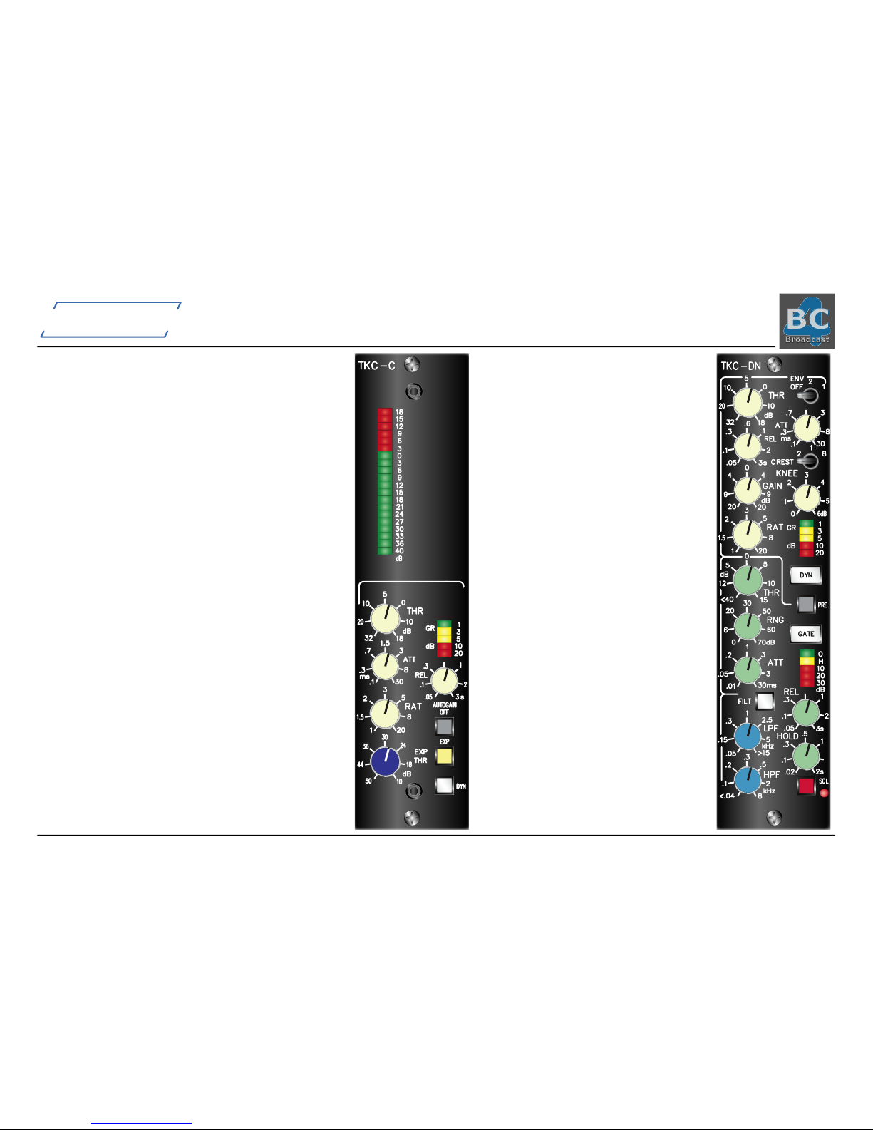
Dynamics
In addition to the selection of different meter
systems, Dynamic Modules can be installed in
the meter bridge.
Several versions of dynamic modules are avai-
lable. The picture shows the TKC-DN, Compres-
sor-Noise Gate that can be used with any mo-
no input channel. If this option is installed with
your console, the dynamics unit is installed abo-
ve the particular channel in the consoles me-
ter bridge. The frame wiring inserts the modu-
le into the channel insert. The external insert
TKC-DN
THR
32
20
10
dB
5
0
10
18
RAT
1
1.5
2
3
5
8
20
HPF
<.04
.1
.2
kHz
.3
.5
2
8
LPF
.05
.15
.3
kHz
1
2.5
5
>15
HOLD
.02
.1
.3
.5
1
2s
SCL
GR
dB
1
3
5
10
20
THR
<40
12
5
dB
0
5
10
15
ATT
.01
.05
.2
1
3
3
30ms
FILT
REL
.05
.1
.31
2
3s
dB
O
H
10
20
30
REL
.05
.1
.3
s
.6
1
2
3
GAIN
20
9
4
dB
0
4
9
20
ATT
.1
.3
.7
ms
3
8
30
ENV
1
2
OFF
RNG
0
6
20
30
50
60
70dB
PRE
CREST
8
1
2
KNEE
0
1
2
3
4
5
6dB
DYN
GATE
TKC-C
ATT
.1
.3
.7
ms
1.5
3
8
30
GR
dB
1
3
5
10
20
RAT
1
1.5
2
3
5
8
20
EXP
AUTOGAIN
OFF
DYN
THR
50
44
36
dB
30
EXP
24
18
10
3
0
3
6
9
18
15
12
9
6
12
15
18
21
24
dB
27
30
33
36
40
THR
32
20
10
dB
5
0
10
18
REL
.05
.1
.3
s
1
2
3

BC
Broadcast
7
is still available; the dynamics modules can be congu-
red to be installed pre the module insert output or post
the insert input. Once the necessary frame PCB‘s and
the additional wiring are installed on particular module
slots, these modules can be upgraded with dynamics mo-
dules at any time. Apart from the TKC-DN, a Compres-
sor-Expander, and combined modules; Compressor-Ex-
pander with PPM meter are available. An upgrade with
the necessary frame PCB‘s and wiring is possible at the
location; however it is more expensive.
Meters
Several different meter versions can be used with all BC4
Broadcast Consoles. While each standard console has a
set of ADT high resolution PPM LED meters included,
which read the program master outputs, the control room
source select and the group outputs, almost any other
signal in the console can be assigned to a meter.
Sources
All modules have congurable meter outputs. With in-
put and group modules, there are usually 4 jumpers that
determine the source signal for an external, additional
meter. Channel ouput, pre fader and post fader signals
and the input signal can be selected. With stereo mo-
dules, stereo or mono, external meters are possible. In
addition to the source selection by jumper blocks per
channel, a separate matrix can be used to add a mono
signal for the meter.
The master modules have meter sends for the auxiliary
outputs, the program masters, the control room source
selectors and the PFL master. If no separate PFL meter
is installed, the control room meter can display the PFL
master as soon as PFL is active by automatic switching.
Standardized atcable connects the meter sends of the
TK-PS
15
178
5
56
5
10
20
3.2
30
1
40
32
10
316
10
560
dB%
0100
TK-PM
15
178
5
56
5
10
20
3.2
30
1
40
32
10
316
10
560
dB%
0100
module with the meter frame boards in the bridge.
The location of the meters is not xed and can be se-
lected by the customer. All meters use a single 24 V
DC supply voltage. A separate supply for the meters
with appropriate capacity is available with each of the
power supply units.
Meter Versions
adt-audio hi-res LED PPM
The TK-PS and TK-PM ADT high resolution LED me-
ters are the standard system for the BC4 consoles. The
meters use 40 LED‘s in a range from +15 dB to -40 dB
with a resolution of 1 dB in the range from +15 to -10
dB and 2 dB down to -30 dB. The release time is line-
arized and can be adjusted to the standard value of
1.5 sec per 20 dB. The attack time is below 1 ms for -1
db display with an burst input signal of 10 ms @ 5 kHz.
The meter is available in stereo and mono versions and
ts into the meter bridge frame boards. It can be used
for all channels and masters of the BC4 system. A corre-
sponding phase correlation meter is also available.
A different scale plate with a display range from + 10
dB to - 45 can be installed alternatively. The level ad-
justment range is more than sufcient to use both sca-
les with all possible nominal levels.
adt-audio 10-LED PPM
An additional, low resolution version with 10 LED‘s
and a total of 30 dB range is available. This is the sa-
me meter that is used with the BC4 input channels in
a format that ts into the meter bridge. These meters
are low cost and can be used for auxiliary send or any
other purpose, alternatively. They are available in mo-
no and stereo congurations.

BC
Broadcast
8
VU Meters
VU Meters can be used al-
ternatively for each meter.
In addition, LED and VU
meters can be mixed in
any way. The VU-meters
are brand Sifam. Theyt
into two channel slots.
Two meters can be in-
stalled, one above each
other. The meters have
an active rectier circuit with level adjustment. The attack and release time is
300 ms. The lead can be adjusted to any desired value.
RTW-Peakmeter
Different versions of 200 segment plasma bar-graph meters, brand RTW, Ger-
many can be installed. These meters can be used for each sour-
ce, alternatively to LED-PPM‘s and VU Meters. The Series 1000
devices can be mounted vertically and t into the module grid.
This series is best choice for use with the BC4 system.
Devices in standard cassette housings 190 x 40 mm (type 1113,
1115 or 1119) must be installed horizontally. A maximum of 2
devices, one above each other can be installed. Special front
panels are available for both, the Series 1000 and Series 1100
units. Phase correlation meters are available as well.
The pictures on this page show some of the available versions.
Please check the RTW website (www.rtw.de) for details about
the different versions.
All RTW devices need special front panels and special wiring.
These meters do not t into the standard meter frameboards.
The series 1000 can be adapted to the frame PCB‘s while the
series 1100 devices require a frame slot where no PBC‘s are
installed.
Loudspeakers
For use as PFL and talkback loudspeaker we offer an active mini speaker that
ts into the meter bridge. One or two speakers can be used in a console. Th-
ey are normally driven by the mini speaker output and can be used in stereo
if two system are installed.The loudspeakers are equipped with
coax wide-band systems. The 8 watts power amplier is supplied
from a separate voltage that is available with all power supply
units. The speaker ts into 4 meter bridge slots.
Additional devices
The picture shows
a TFT multifunc-
tion display, RTW
Portamonitor. Such
devices can be inte-
grated into the me-
terbridge with spe-
cial made front pa-
nels if they t into
the height of the
top plate (145 mm)
and if the depth is
not more than 100
mm. Please ask for
details.

BC
Broadcast
9
2. Installation of the console
This chapter is only of importance if the unit is not delivered and installed
by adt-audio or one of its representatives. In this case, the console system
is delivered by a forwarding agency. You will receive several wooden boxes
that contain the console, the oor stand, the power supply units, and the
accessories. To keep the total weight of the main box as low as possible,
the main box contains only the main frame of the console, everything else
is packed in additional boxes. Since the total weight of the console frame
box is considerable, it might be a problem to unload the main case. As
soon as we have shipped the console system, we will inform you about
the details of shipment. Please get in touch with the local ofce of the
forwarding agency to clear up all details about the unloading of the boxes.
The total weight of the entire system depends on the size of the frame
and on the versions of modules. In any case, the total weight of a BC4
broadcast console system will be between 100 kg/220 lbs (16 channel)
and 300 kg/660 lbs (72 channel). Two persons can easily handle the
power supply, accessories and other boxes.
Unpacking
Make sure that you have the following tools at hand:
A set of screwdrivers for Philips head screws and
metric Allen keys 1.5 to 4 mm
A set of metric spanners, from 10 to 19 mm
Please unpack all the other boxes before unpacking the main box. If your
console has a oor stand, you will need the oor stand to assemble the
frame. In addition, the oor stand box also contains a cardboard box with
screws and other small parts that are necessary for the assembly of the
frame. This box also contains an exploded view, drawing of the frame, and
the wooden side panels.
Open the main box with the console and remove the lid and all end walls.
The console frame is xed to the base plate of the box with 4 screws. You
can reach these screws from the bottom of the box. Remove the screws to
free the main frame.
Check carefully to verify that the console was not damaged during transit.
If there is damage, inform the forwarder before you continue. Do not alter
anything and make sure to take some pictures of the damage. In most
cases, transport insurance will cover any damage; this however, depends
on the details of the purchase. In any case, you are supposed to inform
the forwarding agency and us immediately.
Depending on the size and the weight of the frame you might need up to 6
persons for the next step, the installation of the oor stand. There are two
separate oor stands, one for each side of the frame. They are xed with
2 screws thru the upper tube of each stand to the ange plate on the left
and right bottom of the main frame. It is the same point that was used to
x the main frame into the transport box.
See the exploded view that contains marks for the lifting points of the
frame.
Do not use the meter bridge as a handle or lifting point when
lifting and/or moving the console.
Use the ange plates and the side panels.
The easiest way to install the oor stand is to sit the console frame on
its connector panel with the fader bank up (in the air). Depending on the
weight of the frame, 4 or 6 persons will be required to lift the frame. For
safety, two persons, (one on either end of the console) should securely
hold the console in place at all times when it is in this position. The bottom
of the frame can now be accessed easily. Attach the two oor stands to
the ange plates and x them in place with the special screws that are
located in the small cardboard box. After this part is accomplished, you
can carefully tilt the entire frame up into the normal operating position.
Make sure that there are enough persons to safely handle the weight of
the console.
To avoid damage, the wooden side panels are packed separately. After
the installation of the oor stand, place the console into the nal position
and unpack the side panels. The panels contain threaded inserts. They

BC
Broadcast
10
are xed to the side panels by a couple of screws. See the exploded view
for the location of the xing points and x the panels on both sides of the
frame. In most cases, the small wooden panels for the meter bridge are
already mounted. If this is not the case with your console, remove the rear
cover sheets on both sides of the meter bridge and x the wooden panels.
Remove the protective foil covering the armrest.
You are now ready to install the power supply. Read the rst chapter of the
manual that contains important information about the installation of the
power supply. Mount the power supply, make sure that it is switched off,
and connect both power cords to the mains socket. If you have a failsafe
power supply, you can use one of the two power supply units for a rst
check. Of course, you can also install the complete power supply system.
Mount both power supply units and the crossover unit into a rack or put it
into its permanent location. Make sure that everything is switched off and
connect all units to the mains supply.
Important note:
Make sure that you install the two power supply units to two different
fuses. If you do not do so, a problem on one of the units that is connected
to this fuse will disable the crossover system.
Switch all units on and check if all control LED’s come on. Switch
everything off again and install the included cables. With a normal cable,
you will have only one cable to connect the power supply and the console.
With a failsafe unit, there are 2 additional cables to connect the two power
supply units to the crossover device. The console must be connected to
the crossover device.
After you have installed all connections, double check for any transport
damage. Check if all the modules are properly installed in the frame. If
you are sure that everything is okay, switch the system on and check if
all control LED’s of the power supply are on. It is a good idea to install
the speaker system in the next step and make a quick test if all channels
work.
3. Operating conditions
Environments
The environmental conditions have a great inuence on the long-term
stability and reliability of the entire console.
Temperature
The recommended operating temperature range is from 10 °C to 45 °C.
The console will also operate at temperatures above and below this limit
of course. However, operating at temperatures outside this range for long
periods will reduce the lifespan of the console.
Under normal conditions, we recommend that you power down the console
if it is not in use. The console is ready for use within a minute. It will reach
a steady operating temperature within the rst hour of operation. There is
no reason to leave the system switched on constantly.
For some reasons it can be of advantage as far as the lifespan of the
console is concerned to leave the system powered on if, for example, the
temperature is not stable, and drops down far below 10 degrees at night.
In this case, it will take a longer period to reach its steady operating state.
Within the rst weeks of operation, the console should run in continuous
operation. Failure of an IC, an electrolytic or other early failure is most
likely in the rst weeks of operation.
Soiling
The console and all its connectors should be kept as dust and dirt free as
possible. If drinks or other liquids are accidentally spilled onto the console,
the concerned modules must be immediately removed and a cleaned.
We recommend the use of Isopropyl alcohol for cleaning the console.
Isopropyl alcohol will not damage the components of the console. The
sooner the remains of any spilled liquid is cleaned, is the less risk there is
of damage.

BC
Broadcast
11
4. Maintainance
A BC4 console requires no regular maintenance. Service is only
required, if there is a failure that makes repair necessary. Almost
all problems can be xed by exchanging a defective module.
Following our recommended procedures for the use and care of the
console will result in an extended lifespan of the console.
Console use
All electromechanical components of the console, such as potentiometers,
switches, faders, and relays are self-cleaning. However, self-cleaning
only occurs when the particular component is in use. The electrical and
mechanical lifespan of these components exceeds the useful life of the
system in any case. A rotary pot, for instance, that has a lifespan of 50000
rotation, will work properly for a period of more than 30 years if it is used
one time in an hour for 8 hours a day and 200 work days per year. Long-
term reliability is directly connected to continuous operation. Fine dust and
hardened grease, will be a problem for components that remain unused
for years. If it is not possible to use all the components of a console
constantly, we recommend that you actuate all pots and switches at least
one time per 6 months to keep the self cleaning process running.
Testing the console
From time to time, (we recommend at least one time per year) all
functions of the mixer should be tested. Check every function, all the
inputs and outputs and all controls and switches of the entire console. If
you are not able to make any necessary repairs immediately, make a note
of all problems that were found for future repairs. With large, complex
consoles, it is a good idea to maintain a logbook at hand that is used to
note all problems in the studio. Since it is likely that most of the problems
will be discovered while working with the console, it is good idea to make
a quick note which includes all the details of the problems such as; the
particular channel, the source signal and any special setting that caused
the problem. This helps a service technician to locate problems. Many
problems that come up in a particular setting only, may not be easily
reconstructed after the end of a session. The more precise the notation in
the logbook, the more likely it is that mistakes that are caused by a bad
cable or anything else that is not a problem of a function of the console
itself, can be found and repaired.
Cleaning
Only non-corrosive cleaners such Isopropyl alcohol should be used
for cleaning the console and its components. Isopropyl alcohol is he
best choice for all parts, including the plastic knobs and caps and the
pushbutton knobs, all electric components and the top plates. More
aggressive cleaners can cause problems because they might corrode
mechanical or electrical components. Do not use any kind of thinner –
you will have to replace all plastic parts that were exposed to the thinner.
Potentiometers and push buttons
Depending on the environmental situation at the location, the grease
inside the switches, rotary pots and slider faders begins to harden within
a period between approximately 6 years and 15 years. It is not possible
to determine an exact time when this occurs, since the environmental
inuence is different from location to location and the frequency of use of
the different components also has an inuence on this condition as well.
It is very easy to prevent these effects just by following these simple
maintenance steps. We recommend that this be done after 6 six years of
operation.
Rotary pots and slider faders:
When the grease between bushing and shaft begins to harden, the pot will
run tight. Apply a small drop of penetrating oil between the shaft and the
bushing and turn the pot 5 to 10 times. Doing this will keep the pots in
good shape for many years.
Pushbutton switches
The grease in the pushbutton switches will also begin to harden. Since
it is the same process, this will usually happen at the same time and it
depends on the environmental conditions and the frequency of use. The
best way to maintain pushbutton switches is the use of a special lubricant,

BC
Broadcast
12
type CRC3-36, brand CRC, Belgium. If you cannot get this oil, you can
order it from the factory.
This cleaner contains a non-aggressive, non-permanent solvent that
dissolves hardened fat and grease effectively. The second component is a
good, non-hardening, penetrating oil that protects the cleaned surface for
a long time. CRC3-36 comes as aerosols that make it easy to apply the
agent.
Using CRC3-36 with pushbutton switches is very easy. Remove a module
and put it on a table so that you can see the topside of the switches.
Press the knob of the aerosol tin carefully while you put the end of the
little tube that comes the tin next to the locker block at the top of the
switch. By pressing the knob carefully, you can produce oil foam. Apply
approximately 1 cubic cm of this foam to each switch that has to be
cleaned. Wait some minutes before you operate each switch 5 to 10 time.
With this procedure, you can keep all the switches in a good shape for an
unlimited period.
DO NOT USE ANY KIND OF CONTACT SPRAYS!
DO NOT USE VASELINE OR SIMILAR GREASE!
DO NOT DIP AN ENTIRE MODULE INTO A CLEANING BATH!
Please follow these rules to avoid trouble. Once you have applied
conventional contact spray to a module, you have to use this repeatedly.
There is no way to remove the spray out of switches or faders unless these
components are replaced. Some technicians use Vaseline as a protection
against corrosion. The biggest problem with Vaseline is that it starts to
melt when the temperature is higher than 40 °C. If Vaseline is used for
the cleaning of switches, you have to deal with the problem that after the
temperature exceeds 40 ° C, the entire contact area of the switch will
be covered in Vaseline. As soon as the temperature drops down below
40 degrees, the fat hardens again. This causes considerable contact
problems. If you put an entire module into a cleaning bath, for instance
of an ultrasonic cleaner, the only effect is, that you distribute all the dirt
equally to the entire module. This means that the dirt will be inside pots,
switches, and everything else. Modules that were treated in this way, will
never work properly again.
Screws
After a period of about 4 years, the power supply unit should be
opened and all screws of the transformer and the prints should be re-
tightened. The thermal situation in a power supply makes it likely that
screws in terminator blocks will loose their contact pressure for the high
temperature difference between the on and off state.
Table of contents
Other adt-audio Music Mixer manuals


