adt-audio SRC 51 User manual

Installation
Manual
Part III:
Console Frame
Installation of the console
Operating conditions
Maintainance
Thermal Considerations
analoge + digitale Tonstudiotechnik Karl Jüngling • Inh. Dipl.-Ing. Gerd Jüngling
4-6 Scholtwiese • Gladbeck • 45966 • NRW • Germany • Phone: 0049 2043 51061 • Fax: 0049 2043 56844
E-Mail: info@adt-audio.com • Internet: www.adt-audio.com www.broadcast-console.com
Version 1.5/13 • English
adt-audio
51
SRC

2
adt-audio
51
SRC
Summary
Preface......................................................... 3
1. Console Frames..................................... 4
General Information................................... 4
Side View...................................................... 4
Frame Width................................................ 4
Master Section............................................ 4
Input Modules............................................. 5
Blindpanels, producers tables.................. 5
Side View / Sectional View ..................... 5
Variantes...................................................... 6
Meterbridge................................................ 6
2. Installation of the console.................... 6
Unpacking................................................... 6
Installing the audio cables........................ 9
3. Operating conditions............................. 9
Environments.............................................. 9
Temperature............................................... 9
Soiling........................................................... 9
4. Maintainance......................................... 9
Console Use..................................................9
Testing the Console.................................. 10
Cleaning..................................................... 10
Potentiometers and push buttons......... 10
Rotary pots and slider faders................. 10
Pushbutton switches............................... 10
Screws........................................................ 11
5. Thermal Considerations................... 11
Support............................................................. 12
Side-View Graphic.......................................... 12
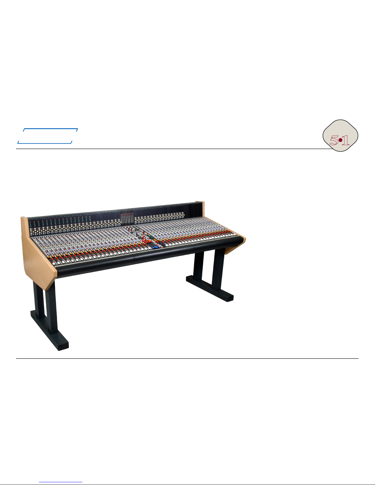
28 Channel SRC51

3
adt-audio
51
SRC
Preface
This manual contains all the information that is necessary to prepare and
plan the installation of the mixing console and accessory components.
Please, read this manual carefully. We point out common mistakes and
problems that are connected with the installation and provide suggestions
to avoid such problems. You will save a lot of time and unnecessary start
up problems by investing a couple of hours in the reading of this manual.
The rst part of the manual contains everything about the power supply
units and crossover devices that are necessary for fail safe power supply
congurations and the implementation of the mains connections. Part 2
is about the audio installation. Besides detailed information about basic
principles of audio installation and the methods of grounding, this chapter
contains all pinning diagrams, pictures and graphics about the locations of
the connectors, and a detailed description of their functions.
Part 3 contains general information about the frame, the assembly of the
console, environmental considerations, the recommended maintenance,
and a couple of remarks about the operation of the console to ensure a
long and problem free lifespan.
This manual concerns the 5.1 surround sound
versions of the SRC51 console system for consoles
without patchbay
Version V1.5/2013
4
adt-audio
51
SRC
1. Frames
General Information
SRC51 console frames are available in many different versions. Almost any frame size with an even number of module slots is possible. The maximum,
overall width of a single frame is 3900 mm. Such a frame has 96 module slots. Several smaller frames can be combined to form a rig on a common, spe-
cial oorstand. All frames are basically oorstand versions, but up to a width of approximately 1500 mm, desktop and build-in version are possible.
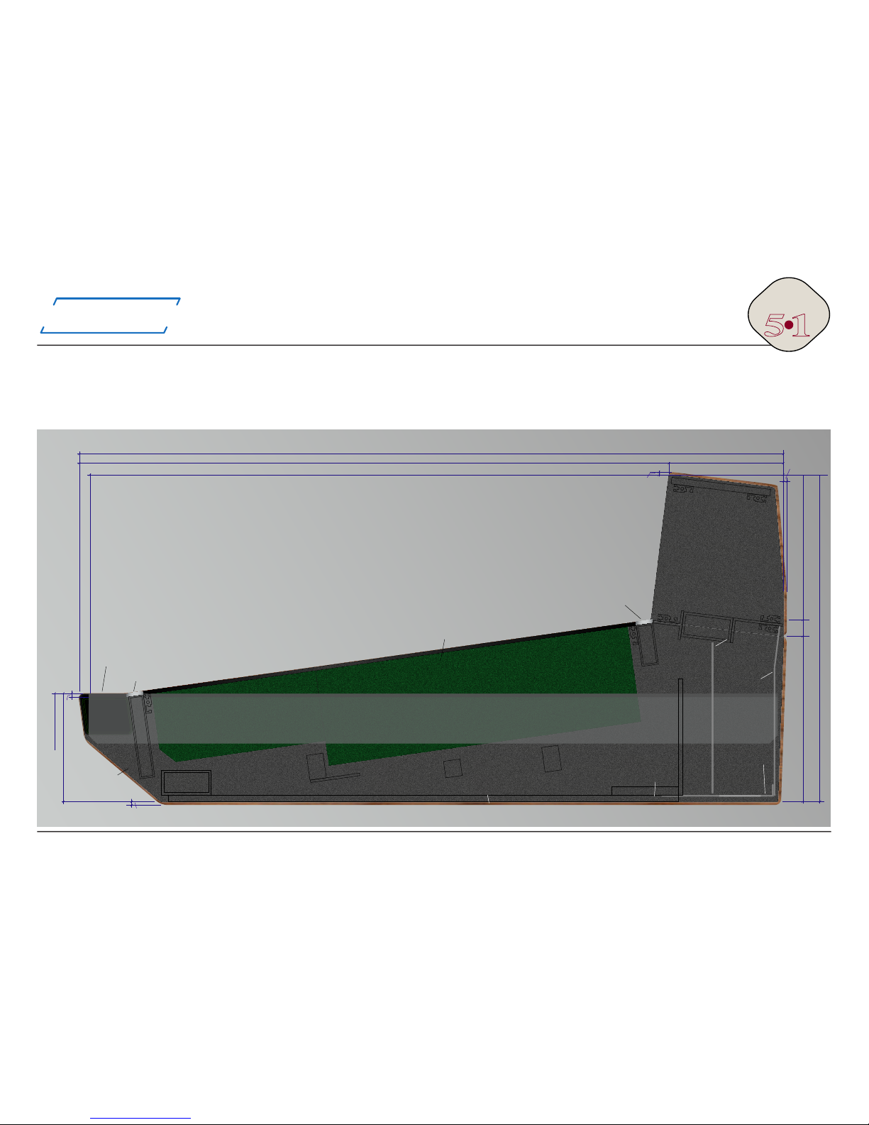
Side View
Please refer to your order conrmation and the
drawings provided with the included informati-
on for the side view and oor plan of your parti-
cular console version. A side view/sectional view
of the frame is on the next page and on the last
page of this manual.
Frame Width
The width of the frames depends of the number
of modules of a particular console. The width of
a single slot is 40 mm. All input modules are ar-
ranged in a grid of 4 modules. Any number of in-
put modules that can divided by 4 is possible. The
width of the master section is 4 slots.
Master Section
The master section can be installed anywhere in
the console between or next to a block of 4 in-
put modules. The master section has a width of
4 modules slots.
Free space for the keyboard of the optional conso-
le automation system has to be considered when
the width of the master section is determined.
The location of the master section in the frame
must be determined with the order. It is not pos-
sible to change this position later.
48 Channel SRC51 Console with IM5 input channels and Dynamics in 40 Channels

5
adt-audio
51
SRC
Input Modules
The frame slots that are used for input modules are compatible with all types of input modules.
However, stereo modules and surround modules use the connectors and the patch bay jacks
differently. Please read the description of the particular modules for details.
Blindpanels, producer tables, remote areas, writing surface
Any even number of blind panels can be installed on the left and right side of the console,
between blocks of 4 input modules, and on the left and right side of the master section. The
only limit is the maximum width of a single frame. These options offer the choice to adapt
a particular frame exactly to the needs. The blindpanels can be standard, single slot or four
slot blindpanels or complete plates of any width. It is also possible to install custom supplied
equipment, like remotes or keyboards into these plates. Of course, the depth of the frame li-
mits this possibility. Blind panels of any size can be black anodized like the standard top plates
or powder coated.
It is possible to install standard channel motherboards under the blind panels if the total width
of the particular panel can be devided by four. This makes it possible to install input modules
when the particular blind panel section is no longer needed.
REAR COVER SHEET
METERBRIDGE
MODULES
(600 x 40 mm / 23.6" x 1.575")
METERING
(TOP PLATE 165 mm / 6.5")
CONSOLE SYSTEM SRC51
SIDE VIEW
MARKER BAR 0.75"/20 mm
(ANODIZED ALUMINUM)
MARKER BAR 0.75"/20 mm
(ANODIZED ALUMINUM)
ALUMINUM
SIDE PANEL
ARM REST APPROX. 2.2"/55mm
(BLACK LEATHER)
REAR GROUND
PANEL
OPTIONAL WOODEN SIDE PANEL
OPTIONAL BRACKET- FOR MOUNTING IN A TABLE OR CONSOLE
CONNECTOR PANELS
DISTANCE OF
CONNECTOR PANELS
APPROX. 3"/75mm
PUNCHED OBLONGS
3" x 2" (75 x 50 mm) FOR
CABLES, 80 mm GRID
THREADED HOLES
FOR CABLE ATTACHMENT
(M4-THREAD)
APPROX.
7 mm
APPROX.
3mm
713 mm / 28.0" 137 mm / 5.4"
850 mm / 33.5"
720 mm / 28.3" ABOVE FLOOR
(WITH OPTIONAL FLOOR STAND)
130 mm / 5.1"
265 mm / 10.4"
395 mm / 15-5"
200 mm / 7.8" 175 mm / 6.9"
20
mm
APPROX.
5mm
4 mm
The side view of the SRC51 frame - see the last page for more details

6
adt-audio
51
SRC
Variantes
All frames are basically oorstand versions. The oorstands are part of the
scope of supply. They are xed to ange plates on the left and right side of the
frame. Desktop versions or build-in version are possible for small frames up to
a width of approximately 1.5 meters. The standard wooden side panels are ma-
de of 30 mm bonded plywood panels with beechwood veneer. They are either
matte nished or stained black. Other versions are possible on special order.
Meterbridge
A meter bridge is standard for all consoles. LED PPM meters, VU meters and
plasma bar graphs are available for all versions of the SRC51 console system.
In addition, dynamics modules with or without meter in mono and stereo ver-
sions can be installed in the meter bridge of the SRC51 consoles.
2. Installation of the console
This chapter is only of importance if the console is not delivered and
installed by adt-audio or one of its representatives. In this case, the
console system is delivered by a forwarding agency. You will receive
several wooden boxes that contain the console, the oor stand, the power
supply units, and the accessories. To keep the total weight of the main
box as low as possible, the main box contains only the main frame of the
console, everything else is packed in additional boxes. Since the total
weight of the console frame box is considerable, it might be a problem to
unload the main case. As soon as we have shipped the console system, we
will inform you about the details of shipment. Please get in touch with the
local ofce of the forwarding agency to clear up all details about unloading
the boxes. The total weight of the entire system depends on the size of
the frame and on the versions of modules. In any case, the total weight of
a SRC51 console system will be between 80kg/176 lbs (16 channel) and
500 kg/1100 lbs (72 channel). Two persons can easily handle the power
supply, accessories and other boxes.
The packing depends on the shipping method and on the forwarder. With
airfreight, in most cases only a base plate for the console frame is needed
while the sides and the top of the console can be covered by stable foil
and/or cardboard.
Unpacking
Make sure that you have the following tools at hand:
A set of screwdrivers for Philips head screws,
metric Allen keys 1.5 to 4 mm, a Torx 10 screwdriver and a metrix pin
type socket wrench 10 mm
A set of metric wrenches, from 10 to 19 mm
A 10 mm and a 12 mm metric allen key for the screws that hold the
oorstand.
Please unpack all the other boxes before unpacking the main box. The rst
step of installing the console ist to prepare the oorstands and the screws
that x the oorstands to the ange plates on the left and right side of
the console’s frame. The screws and some other accessories are packed
together with the wooden side panels in the main box.
Open the main box with the console and remove everything apart from the
console that is xed to the base plate of the box with 4 M12 screws. You
can reach these screws from the bottom of the box. Remove the screws,
using an mm allen key, to free the main frame.
Check carefully to verify that the console was not damaged during transit.
If there is any damage, inform the forwarder before you continue. Do
not alter anything and make sure to take some pictures of the damage.
In most cases, transport insurance will cover any damage; this however,
depends on the details of the purchase. In any case, you are supposed to
inform the forwarding agency and us immediately. A mechanical damage
can be the cause for electrical problems, damaged or broken pcb’s or other
problems that might be hidden until you make a nal and complete test of
the entire system.
Depending on the size and the weight of the frame you might need up to 6
persons for the next step, the installation of the oor stand. There are two
separate oor stands, one for each side of the frame. They are xed with
2 M12 allen screws each thru the upper plate of each stand to the ange
plate on the left and right bottom of the main frame. It is the same point
that was used to x the main frame in the transport box.

7
adt-audio
51
SRC
Do not use the meter bridge as a handle or lifting point when lifting and/
or moving the console.
Use the ange plates and the side panels. In case that you need to transport the
frame thru windows, stairways, or if you have to lift the frame, it’s a good idea to
use the M12 screws for the oorstands as xing point for handles or ropes that
you might need for the transport. The ange plates on the console bottom are very
stable and can hold the entire weight of the console frame in any position.
Additional M12 threads in the side panels of the console can be used for M12
eyeball screws for easier handling of the frame. The eyeball screws are part of the
standard accessory kit.
The easiest way to install the oor stand is to sit the console frame on its
connector panel with the fader bank up (in the air). Depending on the weight of
the frame, 4 or 6 persons will be required to lift the frame. For safety, two persons,
(one on either end of the console) should securely hold the console in place at all
times when it is in this position. The bottom of the frame can now be accessed
easily. Attach the two oor stands to the ange plates and x them in place with
the M16 allen screws. Make sure that you include the washers and the snap rings.
After this part is accomplished, you can carefully tilt the entire frame up into the
normal operating position. Make sure that there are enough persons to handle the
weight of the console safely.
To avoid damage, the wooden side panels are packed separately. After the
installation of the oor stand, place the console into the nal position and unpack
the side panels. Usually the panels contain threaded inserts or have pre-drilled
holes. They are xed to the side panels by a couple of screws. The position of the
panels explains itself, just match the threaded inserts or pre-drilled holes with the
free holes in the side panels of the frame. In most cases, the small wooden panels
for the meter bridge will be already mounted. If this is not the case with your
console, remove the rear cover sheets on both sides of the meter bridge and x
the wooden panels with the wood screws included in the accessory kit.
In most cases, the armrest is already mounted when you get the console. If this is
the case, it is protected by a foil. Just remove the foil covering the armrest.
In case that the transport is very complicated, the armrest might not be mounted.
If this is the case you need to x it to the rectangular tube at the front of the
Left Rear with Floorstand
and wood

8
adt-audio
51
SRC
console frame. You will nd the necessary screws in the accessorie box.
The armrest has been prepared for mounting at the factory. It’s xed by
screws thru holes in the frame. Please check for the pre drilled holes in the
armrest, put it in place and x the armrest from the inside. If the modules
are installed, you need to remove modules to access the holes.
You are now ready to install the power supply. Read the rst chapter of
the manual that contains important information on the installation of the
power supply. Mount the power supply, make sure that it is switched off,
and connect the power cord to the mains socket.
If you have a failsafe power supply, you can use one of the two power
supply units for a rst check. Of course, you can also install the complete
power supply system. Mount both power supply units and the crossover
unit into a rack or put it into its permanent location. Make sure that
everything is switched off and connect all units to the mains supply.
Important note:
Make sure that you install the two power supply units to two different
fuses. If you do not do so, a
problem on one of the units that
is connected to this fuse will
disable the crossover system.
Switch all units on and check if
all control LED’s are working.
Switch everything off again and
install the included cables. With
a standard console, you will have
only one cable to connect the
power supply and the console.
With a failsafe unit, there are 2
additional cables to connect the
two power supply units to the
crossover device. The console
Rear View with Cover Sheets
partly removed
Cable Inlets

9
adt-audio
51
SRC
must be connected to the crossover device.
After you have installed all connections, double check for any transport
damage. Check if all the modules are properly installed in the frame. If
you are sure that everything is okay, switch the system on and check if
all control LED’s of the power supply are on. It is a good idea to install the
speaker system in the next step and make a quick test if all channels are
working.
It is a good idea to make a complete check of all console functions, before
you plug in your audio installation. If you do so, you are sure that the
console is working properly and any problem can only be caused by the
installation. This makes it a lot easier to nd the reasons for any problems.
Installing the audio cables
The entire connector bay is located inside the console and can be hidden
behind cover sheets with ventilation slots. The inlets for the audio cables
are in the rear bottom of the console frame.
3. Operating conditions
Environments
Environmental conditions have great inuence on the long-term stability
and reliability of the entire console.
Temperature
The recommended operating temperature range is from 10 °C to 45 °C.
The console will also operate at temperatures above and below this limit
of course. However, operating at temperatures outside this range for long
periods can reduce the lifespan of the console.
Under normal conditions, we recommend that you power down the console
if it is not in use. The console is ready for use within a minute. It will reach
a steady operating temperature within the rst hour of operation. There is
no reason to leave the system switched on constantly.
For some reasons it can be of advantage as far as the lifespan of the
console is concerned to leave the system powered on if, for example, the
temperature is not stable, and drops down far below 10 degrees at night.
In this case, it will take a longer period to reach its steady operating state.
Within the rst weeks of operation, the console should not run in
continuous operation. Failure of an IC, an electrolytic or other early failure
is most likely in the rst weeks of operation.
Soiling
The console and all its connectors should be kept as dust and dirt free as
possible. If drinks or other liquids are accidentally spilled onto the console,
the concerned modules must be immediately removed and cleaned. We
recommend the use of isopropyl alcohol for cleaning the console. Isopropyl
alcohol will not damage the components of the console. The sooner the
remains of any spilled liquid is cleaned, is the less risk there is of damage.
4. Maintainance
A SRC51 console requires no regular maintenance. Service is only
required, if there is a failure that makes repair necessary. Almost
all problems can be xed by exchanging a defective module.
Following our recommended procedures for the use and care of the
console will result in an extended lifespan of the console.
Console use
All electromechanical components of the console, such as potentiometers,
switches, faders, and relays are self-cleaning. However, self-cleaning
only occurs when the particular component is in use. The electrical and
mechanical lifespan of these components exceeds the useful life of the
system in any case. A rotary pot, for instance, that has a lifespan of 50000
rotation, will work properly for a period of more than 30 years if it is used
one time in an hour for 8 hours a day and 200 work days per year. Long-
term reliability is directly connected to continuous operation. Fine dust and
hardened grease, will be a problem for components that remain unused
for years. If it is not possible to use all the components of a console
constantly, we recommend that you actuate all pots and switches at least
one time per 6 months 3 to 6 times to keep the self cleaning process

10
adt-audio
51
SRC
running.
Testing the console
From time to time, (we recommend at least one time per year) all
functions of the mixer should be tested. Check every function, all the
inputs and outputs and all controls and switches of the entire console. If
you are not able to make any necessary repairs immediately, make a note
of all problems that were found for future repairs. With large, complex
consoles, it is a good idea to maintain a logbook at hand that is used to
note all problems in the studio. Since it is likely that most of the problems
will be discovered while working with the console, it is good idea to make
a quick note which includes all the details of the problems such as; the
particular channel, the source signal and any special setting that caused
the problem. This helps a service technician to locate problems. Many
problems that come up in a particular setting only, may not be easily
reconstructed after the end of a session. The more precise the notation in
the logbook, the more likely it is that problems that are caused by a bad
cable or anything else that is not a problem of a function of the console
itself, can be found and repaired.
Cleaning
Only non-corrosive cleaners such isopropyl alcohol should be used
for cleaning the console and its components. Isopropyl alcohol is he
best choice for all parts, including the plastic knobs and caps and the
pushbutton knobs, all electric components and the top plates. More
aggressive cleaners can cause problems because they might corrode
mechanical or electrical components. Do not use any kind of thinner –
you will have to replace all plastic parts that were exposed to the thinner.
Potentiometers and push buttons
Depending on the environmental situation at the location, the grease
inside the switches, rotary pots and slider faders begins to harden within
a period between approximately 6 years and 15 years. It is not possible
to determine an exact time when this occurs, since the environmental
inuence is different from location to location and the frequency of use of
the different components has an inuence on this condition as well.
It is very easy to prevent these effects just by following these simple
maintenance steps. We recommend that this be done after 6 six years of
operation.
Rotary pots and slider faders:
When the grease between bushing and shaft begins to harden, the pot will
run tight. Apply a small drop of penetrating oil between the shaft and the
bushing and turn the pot 5 to 10 times. Doing this will keep the pots in
good shape for many years.
Pushbutton switches
The grease in the pushbutton switches will also begin to harden. Since
it is the same process, this will usually happen at the same time and it
depends on the environmental conditions and the frequency of use. The
best way to maintain pushbutton switches is the use of a special lubricant,
type CRC3-36, brand CRC, Belgium. If you cannot get this oil, you can
order it from the factory.
This cleaner contains a non-aggressive, non-permanent solvent that
dissolves hardened fat and grease effectively. The second component is a
good, non-hardening, penetrating oil that protects the cleaned surface for
a long time. CRC3-36 comes as aerosols that make it easy to apply the
agent.
Using CRC3-36 with pushbutton switches is very easy. Remove a module
and put it on a table so that you can see the topside of the switches.
Press the knob of the aerosol tin carefully while you put the end of the
little tube that comes with the tin next to the locker block at the top of
the switch. By pressing the knob carefully, you can produce oil foam.
Apply approximately 1 cubic cm of this foam to each switch that has to be
cleaned. Wait some minutes before you operate each switch 5 to 20 times.
With this procedure, you can keep all the switches in a good shape for an
unlimited period.
DO NOT USE ANY KIND OF CONTACT SPRAYS!
DO NOT USE VASELINE OR SIMILAR GREASE!
DO NOT DIP AN ENTIRE MODULE INTO A CLEANING BATH!

11
adt-audio
51
SRC
Please follow these rules to avoid trouble. Once you have applied
conventional contact spray to a module, you have to use this repeatedly.
There is no way to remove the spray out of switches or faders unless these
components are replaced. Some technicians use Vaseline as a protection
against corrosion. The biggest problem with Vaseline is that it starts to
melt when the temperature is higher than 40 °C. If Vaseline is used for
cleaning of switches, you have to deal with the problem that after the
temperature exceeds 40 ° C, the entire contact area of the switch will
be covered in Vaseline. As soon as the temperature drops down below
40 degrees, the fat hardens again. This causes considerable contact
problems. If you put an entire module into a cleaning bath, for instance
of an ultrasonic cleaner, the only effect is, that you distribute all the dirt
equally to the entire module. This means that the dirt will be inside pots,
switches, and everything else. Modules that were treated in this way, will
never work properly again.
Screws
After a period of about 4 years, the power supply unit should be opened
and all screws of the transformer and the pcb’s should be re-tightened.
The thermal situation in a power supply makes it likely that screws
in terminator blocks will loose their contact pressure due to the high
temperature difference between the on and off state.
5. Thermal Considerations
Any console will dissapate a considerable amount of heat to the room.
A typical average value of the power dissapation of a console with 40
channel is 1000 watts. Depending on the number and version of the input
modules and the setting of the console, output load, and the actual levels,
it may be a little less or a lot more. From that perspective, please consider
the console just like an electric heater system. As far as air ow is
concerned, any console is a faulty design. Rising heat from the electronics
on the module’s pbc’s is blocked by the face plates and causes the entire
console to heat up. Any SRC51 console has ventilation slots in the cover
sheets below the armrest and a free pass for hot air at the rear side above
the connector panels. However, the console cannot terminate the heat and
without appropriate measures in the room the temperature in the console
and on the face plates will rise the more the longer the console is powered
on.
It is up to you to take care that an appropriate ventilation system
and/or air condition system is installed in the control room. If you
don’t install such a system, the temperature of the console will be
considerably higher than necessary. This will reduce the life span
and cause more problems with defective components and wear
and tear.
Please follow these basic rules:
Do not cover the ventilation slots below the armrest and make
sure that the air outlet above the connector panels is free.
The offtake of your ventilation system or air condition should be
directly behind the air outlet on the rear side of the console.
The capacity of the air condition should at least match the average
power dissapation of the console. If you’re in doubt, please ask for
the power dissapation of your setup.
Optional, forced Ventilation
If the natural ventilation system of the console frame is not sufcient to
maintain an appropriate airow, an optional forced ventilation by fans can
be installed in all versions of the SRC51 console frames. This might be the
case if the console is installed directly in front of a wall or in any other way
that causes limited efciency of the natural ventilation.
With this option, a 60 mm fan is installed per two channels in the frame
right behind the air outlet. An additional supply voltage is included with
all UPS10 and UPS25 power supply units. This voltage can be controlled
by a trimpot on the top plate of the unit. The control range of the voltage
makes it possible to nd a compromize between efcient cooling and
noise. Setting the fans to the lowest possible speed will cause a drop in
temperature of approx. 15 °C, which is more than sufcient to maintain
‘cool’ top plates and appropriate operating conditions for the electronics.
The additional noise that is caused by such a setting if very low; the noise
12
adt-audio
51
SRC
REAR COVER SHEET
METERBRIDGE
MODULES
(600 x 40 mm / 23.6" x 1.575")
METERING
(TOP PLATE 165 mm / 6.5")
CONSOLE SYSTEM SRC51
SIDE VIEW
MARKER BAR 0.75"/20 mm
(ANODIZED ALUMINUM)
MARKER BAR 0.75"/20 mm
(ANODIZED ALUMINUM)
ALUMINUM
SIDE PANEL
ARM REST APPROX. 2.2"/55mm
(BLACK LEATHER)
REAR GROUND
PANEL
OPTIONAL WOODEN SIDE PANEL
OPTIONAL BRACKET- FOR MOUNTING IN A TABLE OR CONSOLE
CONNECTOR PANELS
DISTANCE OF
CONNECTOR PANELS
APPROX. 3"/75mm
PUNCHED OBLONGS
3" x 2" (75 x 50 mm) FOR
CABLES, 80 mm GRID
THREADED HOLES
FOR CABLE ATTACHMENT
(M4-THREAD)
APPROX.
7 mm
APPROX.
3mm
713 mm / 28.0" 137 mm / 5.4"
850 mm / 33.5"
720 mm / 28.3" ABOVE FLOOR
(WITH OPTIONAL FLOOR STAND)
130 mm / 5.1"
265 mm / 10.4"
395 mm / 15-5"
200 mm / 7.8" 175 mm / 6.9"
20
mm
APPROX.
5mm
4 mm
of a single computer system is higher.
Support
If you need any kind of support please get in touch with us by email
Other manuals for SRC 51
2
Table of contents
Other adt-audio Music Mixer manuals


