adt-audio ToolMod Faderbox User manual

adt-audio
analoge + digitale Tonstudiotechnik Karl Jüngling
Inh. Dipl.-Ing. Gerd Jüngling e. K.
4-6, Scholtwiese • Gladbeck • D45966 • Germany
Phone: 0049 2043 51061 • Fax: 0049 2043 56844
Email: sales@adt-audio.com
Web: www.adt-audio.com + www.adt-audio.de
Webstore: www.pro-audio-store.de
Version 1.0/2014/EN
ToolMod Faderbox
modulare Consoles
Installation Manual
®®

adt-audio
ToolMod Faderbox
modular Summing Mixer
2
®®
Content
Preface and Disclaimer.....3
Copyright....3
Trade Marks....3
CE-Declaration of Conformity....3
Environmental Protection....3
Important Safety Hints....4
Water und Humidity....4
Insertion of Objects or Fluid....4
Power Supply Units....5
Ventilation Slots....6
Module Frames....6
Installing and removing Modules....7
Repairs....8
Spare Parts....8
Safety Test....8
Factory Repair....8
Cleaning....9
Power Supply....9
Mains Voltages and Frequencies....9
Output Voltages....9
Power Cables....9
Power Supply Rating....10
Power Supply Units....10
Power Supply Unit ToolPwr-M....10
Power Supply Unit ToolPwr-S....11
Power Supply Unit ToolPwr-E....11
Phantom Power....11
Power Supply Outputs....11
Power Supply Connections between
Power Supply Unit and Frame....11
Power Supply Connections
between Frames....12
Power Supply Pin Assignment....12
Important Hint:
maximum Current per Cable....12
Grounding and Protective Ground....13
Important Hint: Do not power on....13
Placement/Installation of the
Power Supply Units....14
Overloading Power Supply Units....14
Overload Effects of Power Supply Units....14
Very high Temperature of the
Heat Sink and the Housing....14
Hum....15
Faderbox Frames.....16
Audio Input and Output Connectors....17
XLR.....17
TRS....17
25-pin D-Sub Connectors.....17
Connector Panels.....17
Power Supply Connectors.....18
Master Outputs.....18
Connectors for the Link System.....19
Connectors in the 5-Channel Frame.....20
Connectors for the
Module Compartments 1 to 4 .....21
Connectors for the fth
Module Compartment.....22
Connectors in 19" Frames.....22
Connectors for the
Module Compartments 1 to 8.....22
Connectors for the Module
Compartments 9, 10, and 11.....24
Connectors in the 20-Channel Frame.....25
Connectors for the Module
Compartments 1 to 8 and 9 to 16.....25
Connectors for the Compartments 17 to
20.....29
Connectors of the
TM612 Control Room Module.....30
CTR1 and CTR2 in 19" and
20-Channel Frames.....30
Master Amplier and Link Interface.....33
Frames without Master-PCB.....39
Master and Group Faders.....40
Master Fader.....40
Sub Group Master Faders.....41
Dimensions.....42
Frame Options.....34
TM601 Mono Input Module.....46
TM602 Stereo Input Module.....48
TM603 M/S Stereo Input Module.....50
TM612 Control Room Module.....52
Audio Installation.....54
Ground.....54
Common Grounding Problems.....54
Video.....54
Antennas.....55
Computer Network Connections.....55
Telephone Lines and Modems.....55
Unbalanced Inputs and Outputs....56
Unbalanced Output ->
balanced ToolMod Input....56
Balanced ToolMod Output ->
unbalanced Input....56
Maintenance....56
Using the Faderbox....57
Testing....57
Cleaning....57
Potentiometers and Push Buttons....58
Rotary Pots and Slider Faders....58
Pushbutton Switches....58
Notes....59
Content

ToolMod Faderbox
modular Summing Mixer
3
adt-audio
®
®
General Information
Preface and Disclaimer
This manual contains general information on the adt-audio® modular summing
mixer system ToolMod® Faderbox.
By no means does this information represent guaranteed particular characte-
ristics or results of use. The information in this manual has been carefully com-
piled and veried.
Due to our policy of continuous product improvement, we reserve the right to
make product changes without prior notice.
All specications are subject to change without notice.
Copyright
This manual is copyright protected. Do not copy, distribute, or translate into
other languages without permission in writing from adt-audio® Karl Juengling.
All rights reserved.
Trade Marks
adt-audio® and ToolMod® are registered trademarks of analoge + digitale Ton-
studiotechnik Karl Juengling. All other trademarks are the property of their re-
spective owners.
CE Declaration of Conformity
Manufacturer: Fa. Karl Juengling
Type of Equipment: Audio Signal Processor
Product: ToolMod Pro-Audio Module System,
consisting of:
Modules, Mounting Frames,
Power Supply Units and Accessories
Compliance Engineer: Gerd Juengling
Test Basis:
EN50081-1:1992, EN50082-1:1992, EN61000-3-3:1995,
EN60065:1993 Class1, EN61000-3-2:2000,
EN60065:2002, EN55013:2001, EN55020:2002,
73/23 EWG; 93/68 EWG
We hereby declare that the construction of the ToolMod system com-
plies with the standards and regulations listed above.
Environmental Protection
This product can be recycled. Products bearing this symbol must not be
thrown away with normal household waste. At the end of the product‘s
adt-audio
ToolMod Faderbox
modular Summing Mixer
4
®®
life, take it to a collection point designated for recycling of electrical and elect-
ronical devices. Find out more about return and collection points through your
local authorities.
The European Waste Electrical and Electronic Equipment (WEEE) Directive was
implemented to reduce the amount of waste going to landlls, thereby redu-
cing the environmental impact on the planet and on human health. Please act
responsibly by recycling used products. If this product is still useable, consider
giving it away or selling it.
WEEE-Registration: DE 59049716
Important Safety Instructions
Please note and retain this information!
Read and follow all safety and operation instructions carefully before you start
using the product!
Heed all warnings!
This manual provides general information on the ToolMod Faderbox. Extensi-
ve information on the entire ToolMod Faderbox system and les for download
can be found on our website www.adt-audio.com.
Water and Humidity
Do not use the devices near water, near a bathtub, in a wet
basement, near a swimming pool, and the like. Do not expose
the devices to rain or moisture.
WARNING: RISK OF DEATH BY ELECTRIC SHOCK!
Insertion of Objects or Fluids
NEVER allow any kind of object to get into the devices thru
ventilation slots or other openings in the housing. You can ea-
sily come into contact with dangerous electric voltage or cause
damaging short circuits. NEVER allow any kind of uids to be
spilled or sprayed on the devices. Such actions can cause da-
mage, dangerous electric shocks, or re.
WARNING: RISK OF DEATH BY ELECTRIC SHOCK!
Safety Instructions

ToolMod Faderbox
modular Summing Mixer
5
adt-audio
®
®
In case an object or fluids got into a device, disconnect the power immedi-
ately and contact a qualified service technician!
Power Supply Units
Do not defeat the safety purpose of the grounding type Euro outlet. Use only
power cables and wall outlets that provide protective ground connection to the
power supply units. Grounding type cables and outlets have two contacts for
the ac line and a third grounding contact. The third, grounding contact is pro-
vided for your safety. If the provided cable does not t into your wall socket,
consult an electrician for replacement.
Protect the power cord from being walked on or pinched particularly at
plugs, convenience receptacles, and the point where they exit from the
power supply unit.
Unplug the power supply units when unused or unattended for long peri-
ods.
Make sure that the voltage selector of the power supply is
set to the correct voltage BEFORE YOU CONNECT THE PO-
WER SUPPLY.
NEVER OPEN THE HOUSING OF A POWER SUPPLY UNIT
BEFORE YOU DISCONNECT THE POWER CORD. Even if the
unit is switched off, dangerous voltage is present inside the
unit. In order to avoid exposure to any residual voltage, the
units should be disconnected from any power source at least
5 minutes before opening!
Make sure that the voltage selector of the power supply is
set to the correct voltage BEFORE YOU CONNECT THE PO-
WER SUPPLY.
The power supply units must be located such that the rear AC
socket and connected power cord are readily accessible.
Avoid any kind of overload in connections to wall sockets,
extension or splitter power cords. Overloads create seri-
ous risk of
FIRE HAZARDS and DEATH BY ELECTRIC SHOCK!
WARNING: RISK OF DEATH BY ELECTRIC SHOCK!
Do not use different fuses for replacement. NEVER replace a fuse with ano-
ther one with higher current values or different tripping behavior. Use on-
Safety Instructions

adt-audio
ToolMod Faderbox
modular Summing Mixer
6
®®
ly fuses with the original values. Other fuses can cause damage, fire, and/
or electric shocks.
WARNING: RISK OF DEATH BY ELECTRIC SHOCK!
Unplug the power supply units before lightning storms or
when unused or unattended for long periods. This will pre-
vent damage to the power supply units from lightning and
power line surges.
WARNING: DO NOT TOUCH OR DISCONNECT DEVICES
DURING A LIGHTNING STORM
RISK OF DEATH BY ELECTRIC SHOCK!
Ventilation slots and/or openings prevent the devices from overheating. Do
not block or cover ventilation openings. Never place the units on a soft sur-
face (carpet, sofa, pillow, etc.). Make sure to provide enough space (4 to 5
cm / 2 inches) around the devices, when mounting into a rack or cabinet.
Do not attempt any alterations to the units without express written appro-
val from adt-audio Karl Juengling! Unauthorized alterations void any war-
ranty and liability!
Module Frames
It is not necessary to remove cover sheets
when installing or removing modules. Mo-
dules can be removed and exchanged after
unbolting the knurled screws that x the
modules in the frame. Additional modu-
les can be installed after removing blind
panels, where necessary.
Do not remove cover sheets of the frames
and do not make any changes. The sup-
ply voltages of +/- 25 volts and 48 volts
DC are accessible inside the frames. Alt-
hough these voltages are low, there is still
the risk of electric shocks.
Important Note:
In no event, open the housing of the power supply units before the power
cord is disconnected. Wait at least 5 minutes after disconnecting the cord
to avoid exposure to residual voltage. Otherwise, no liability will be assu-
med.
Safety Instructions

ToolMod Faderbox
modular Summing Mixer
7
adt-audio
®
®
Installing and removing Modules
Before you begin, disconnect the devices from the power line, and wait 5
minutes until any residual voltage has discharged.
Before you reconnect the power and switch on, make sure that all modules
fit into the mating plugs in the frame and that all modules are fixed.
Do not install any modules with visible damages.
Modules can have sharp corners and edges,
sharp tips of screws, pointed wire ends
and other dangerous parts. There is the
risk of injury. Be careful, make sure that
you do not hurt yourself, and take care
where to touch the modules.
Never use control knobs as handle to remove
the modules from the frame. The xing screws are knurled neck collar screws.
After unbolting the modules from the frame,
the screws t into taps in the faceplates and
can be used as handles for removing. Use
a torx screwdriver size T8 for these screws. If you use
low quality allen keys, the screws might be damaged
so they can't be removed.
Pull out the modules always
using the remover screws. Other-
wise, there is the risk of damage for pots and other con-
trol elements.
Like computer add-on boards, the PCB’s of the modules do not have cover
sheets. Make sure that you act with appropriate caution and do not touch any
components.
Qualified personnel should perform installing and removing. With respect
to possible physical damage or injuries, any manipulation is at your own
risk and we are not liable for any physical damage or injury.
Safety Instructions

adt-audio
ToolMod Faderbox
modular Summing Mixer
8
®®
Safety Instructions
Repairs
In case that:
• you think repairs are necessary
• objects or uids have gotten into a device
• the device fell to the ground
• the device is otherwise mechanically damaged
• the device is not working properly
• the power cord is damaged
• the device was exposed to rain
• the device fell into water
Disconnect the power immediately and contact a qualified service tech-
nician.
Make sure to inform the service technician about anything that has hap-
pened to the device.
In case that the power cord is damaged, do not touch the cord or the de-
vice but switch of the main circuit breaker before disconnecting the pow-
er cord.
WARNING :
RISK OF DEATH BY ELECTRIC SHOCK!
Spare Parts
Make sure that only original parts are used for repair or replacement. Wrong
spare parts may cause re, electric shocks, subsequent damages, and other dan-
gerous risks. Otherwise, the warranty is void and no liability will be assumed.
Safety Test
Insist that the service technician conducts a thorough safety test to ensure that
the condition of the repaired device is safe and up to factory standards.
Factory Repair
If you intend to send defective devices to the factory, please get in touch with
us by phone (0049 2043 51061) or by email (support (at) adt-audio.com) and
let us know:
• Type and serial number of the defective device
• Date of purchase and name of the dealer,

ToolMod Faderbox
modular Summing Mixer
9
adt-audio
®
®
if you have not purchased directly from the factory
• a brief description of the problem and of the history
(uids in the device, something that happened, etc.)
We will tell you how to proceed.
Cleaning
Before you begin to clean devices, disconnect the power cord. Clean only with
a dry cloth and do not use any solvents or sprays! For removing stubborn conta-
minations, you may use a cloth soaked with isopropyl alcohol as cleaning agent.
Isopropyl alcohol does not attack the powder coating and the plastic parts.
Make sure that the alcohol is entirely evaporated before you reconnect the
unit to the power line. Otherwise, you risk fire and electrical shocks!
Power Supply
The ToolMod Faderbox uses the same power supply units, cables, and con-
nectors as the ToolMod Pro-Audio module system, the ToolMix summing
boxes, and the ToolKit channel strip. A range of linear power supply units
is available for these devices. Using the same power supply unit for sever-
al different units is possible.
Mains Voltages and Frequencies
All power supply units are suited for 230 and 115 volts ac power lines with 50
or 60 Hz.
Output Voltages
All supply units deliver +/- 25 volts for the au-
dio ampliers of the ToolMod Faderbox and
an additional 48 volts phantom power for con-
denser microphones.
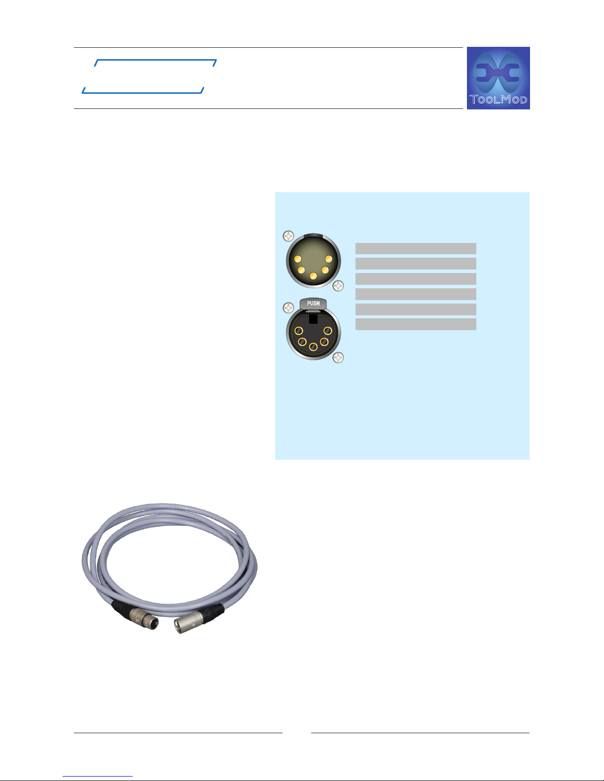
Power Cables
6 core, high cross section control cables with
5-pin XLR connectors are used for the connec-
tion between the power supply units and the
frames and between frames. The pin assign-
ment of the 5-pin XLR connectors is compa-
Power Supply

adt-audio
ToolMod Faderbox
modular Summing Mixer
10
®®
Power Supply
tible with the ToolMix series of summing boxes, the ToolKit channel strip and
the ToolMod Faderbox. The power supply units can be used with any combina-
tion of these devices without any disadvantage, if the capacity of the particular
power supply unit is sufcient.
TM400 Series ToolMod Consoles come with a 5-pin XLR power output connec-
tor for all ToolMod, ToolMix, and ToolKit units. Using the power supply unit of
a ToolMod console with sufcient capacity for these units is also possible.
Power Supply Rating
Type and number of modules and units determine the version of the required
power supply unit. The three standard power supply units for the adt-audio Tool
devices can be used with almost all existing system setups. Which power supply
unit is suited for a particular setup is determined by the current consumption
of the modules and units and, on rare occasions, by the operation level and the
load on the outputs. The current consumption of the modules and other Tool
devices is listed in the technical specications of the particular device in the ma-
nuals and on the web pages (www.adt-audio.com). The operation level and the
load is only important if the load on a considerable number of outputs is lower
than 2 kΩ while the operation level is close to the headroom of + 30 dBu.
If you are in doubt which power supply is required for a particular setup,
please ask by phone or email.
Power Supply Units
There are three standard power supply units with different capacities:
ToolPwr-M, ToolPwr-S and ToolPwr-E
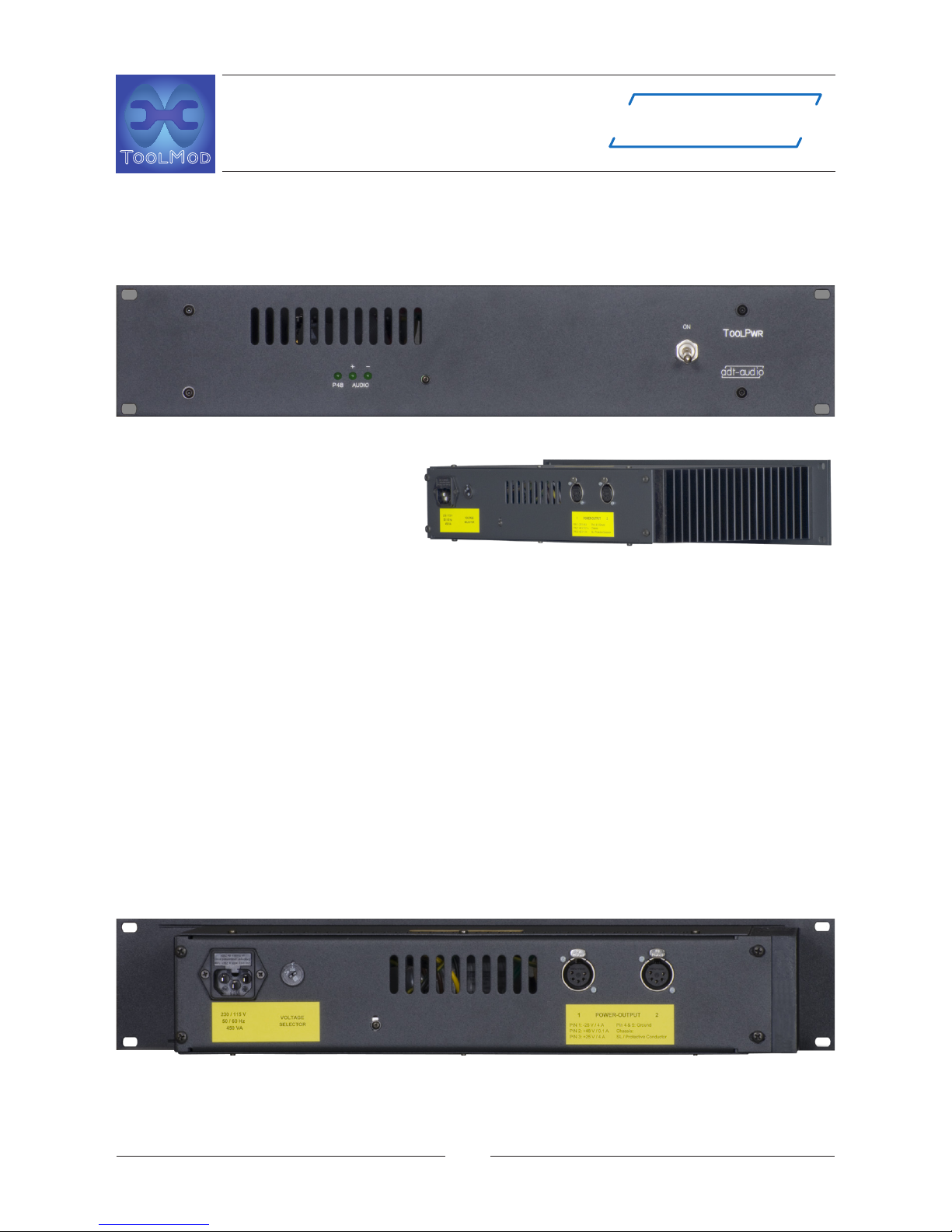
ToolPwr-M
The ToolPwr-M is a desk-
top unit with a nominal
output current of 1 amps
and a peak output cur-
rent of 1.5 amps. The
ToolPwr-M comes with
a single 5-pin XLR output
connector. The nominal
power is 100 watts.
ToolMod Faderbox
modular Summing Mixer
11
adt-audio
®
®
Power Supply
ToolPwr-S
The ToolPwr-S is a 2U-high 19“ unit with a nominal output current of 2,5 amps
and a peak output current of 4 amps. The ToolPwr-S comes with two 5-pin XLR
output connectors. The nominal power is 230 watts.
ToolPwr-E
Like the ToolPwr-S, the ToolPwr-
E is a 2U-high 19“ unit; however,
the nominal output current is 5
amps and the peak output current
is 7 amps. The ToolPwr-E comes
with a bigger power transformer, a larger heat sink, high power voltage regula-
tors and bigger load capacitors. Like the ToolPwr-S it has two 5-pin XLR output
connectors. The nominal power is 450 watts.
Phantom Power
The considerations of the output current refers to the capacity of the audio sup-
ply voltages. The 48 volts phantom supply in each of the power supply units is
designed to supply high current condenser microphones if the entire capaci-
ty of the audio supply is used for microphone ampliers. Therefore, there is no
need to consider the capacity of the phantom power supply.
Power Supply Outputs
Depending on the power supply unit, there are one or two 5-pin XLR output
connectors. The picture shows the rear panel of a ToolPwr-S with 2 output con-
nectors, wired in parallel.
Power Supply Connections between Power Supply Unit and Frame
6 core, high cross section control cables, tted with 5-pin XLR plugs are used
for the power cables. The cross section of each core is 0.75 mm2 = AWG18. The
adt-audio
ToolMod Faderbox
modular Summing Mixer
12
®®
Power Supply
5-pin XLR connectors and the voltage drop along the cable determine the ma-
ximum current of 3 amps.
Power Supply Connections between Frames
All ToolMod Faderbox frames come with a 5-pin male XLR and a parallel 5-pin
female XLR. Several frames can be
connected in daisy chain mode, as
long the total current is lower than
3 amps. All power cables are ex-
tension cords with a female and a
male plug, therefore. The picture
shows the rear panel of a 1U high
ToolMod frame.
Power Supply
Pin Assignment
The pin assignment of the power
supply unit and the ToolMod Fa-
derbox frame matches the pin as-
signment of all other adt-audio Tool
devices. Any combination of these
devices can be connected to any
power supply and any other Tool
unit, as long as the capacity of the
power supply unit is sufcient.
Standard Power Cables and
custom Cables
The following standard power cables are availa-
ble from stock:
10 ft./3m, 5 ft./1.5 m, 3 ft./1 m, 2 ft./60 cm,
and 1 ft./30 cm.
Custom cables, up to 6 meters are available at
short notice. The 10 ft./3 m versions are usually
used for connecting the power supply unit to
the rst frame. The shorter cables are used to
connect several frames in daisy chain mode.
IMPORTANT HINT:
The maximum current per cable must not exceed 3 amps.
The XLR connectors are not designed for higher currents than 3 amps. In addi-
1 AUDIO SUPPLY - 25 V
2 PHANTOM SUPPLY + 48 V
3 AUDIO SUPPLY + 25 V
4 AUDIO GROUND
5 AUDIO GROUND
CASE - PROTECTIVE GROUND
5-PIN XLR
PROTECTIVE GROUND AND CHASSIS ARE
CONNECTED
AUDIO GROUND AND CHASSIS ARE CONNECTED
IN THE POWER SUPPLY UNIT
USE 6 PIN CABLES
ATTENTION:
MAXIMUM CURRENT OF CONNECTORS IS
3 AMPERE
DO NOT CONNECT MORE THAN 4 TOOL DEVICES
IN DAISY CHAIN MODE
TOOLKIT/TOOLMIX/TOOLMOD
POWER SUPPLY CONNECTORS

ToolMod Faderbox
modular Summing Mixer
13
adt-audio
®
®
Power Supply
tion to a higher failure probability of the connectors, higher current results in
higher voltage drop along the cable and therefore a lower supply voltage of the
modules. This may result in a reduction of the headroom and degraded transi-
ent performance.
To make sure that the maximum current will not exceed 3 amps with a rea-
sonable safety margin, connect not more than a single 4U high frame, two
2U high frames, or four 1U-high frames to a single power supply output.
Of course this is only a rule of thumb. The exact current consumption results
from the addition of the current consumption of the modules, and the load re-
sistance combined with the operation level, as explained in detail above.
Grounding and Protective Ground
As factory standard, the protective ground from the Euro inlet of the power sup-
ply unit is connected via the power supply cable to the chassis of the frame, the
audio ground, and the screen pins of all connectors. This principle ensures that
all accessible parts are connected to the protective ground. However, the con-
nections between the different grounds are not part of the basic design of the
ToolMod Faderbox series. The three ground circuits protective ground = chas-
sis, audio ground = 0 volts of the power supply, and screen-ground = all scree-
ning pins of the audio connectors, are fully isolated from each other and con-
nected only at one point inside each frame. If ground loops show up due to the
connection of the protective ground to the audio ground and/or screen ground,
it is possible to isolate the ground circuits. For safety reasons, it is not possible
to isolate the protective ground from the chassis. In any case it is necessary to
ensure that the safety of the system is ensured if the ground connections are
removed. Contact us before you change anything!
IMPORTANT HINT:
Do not power on the system before the power cables are installed!
If you unplug or plug in a power cable while the system is under power by ac-
cident, there is no risk that a module or the power supply unit becomes defec-
tive. If the load on the power supply unit is low, the system will keep working.
However, if the load of the power supply unit is high, the inrush current when
you plug in a power cable is very high, since the oversized load capacitors in all
modules have to be loaded. In this case it might happen that one of the protec-
tion circuits in the power supply unit is triggered and shuts down one or both
audio supply voltages. This results in very high background noise and a redu-
ced intensity of the control LED of the particular supply voltage on the face-
plate of the power supply unit. If this happens, switch off, wait about 1 minu-
te, and switch on again.

adt-audio
ToolMod Faderbox
modular Summing Mixer
14
®®
Power Supply
Placement/Installation of the Power Supply Units.
Do not place or install the power supply unit directly below, above, or next
to a ToolMod frame.
The most important reason for external power supply units is the electro magne-
tic eld of the toroidal power transformer that can only be effectively screened
by MU-metal at very high cost. Even though the magnetic eld of a high quali-
ty toroidal transformer is a lot lower than the eld of a cheap standard transfor-
mer, it is still existing and may induce hum into sensitive devices, especially tho-
se with input and output transformer and/or inductors that are not sufciently
screened and/or with high gain and high input impedance. Since the intensity
of an electro magnetic eld is reciprocally proportional to the second power of
the distance, any disturbance caused by magnetic elds is reduced to a quarter
is the distance is doubled. If you install a power supply next to an audio device
with sensitive circuitry, you reduce the advantage of the external power unit si-
gnicantly. With a proper placement of the power supply unit, about 1 m away
from any audio gear, you can install any module in any module compartment
without hum or other disturbances from electro magnetic elds. If you have to
deal with such problems and no improvement can be achieved when moving
the power supply unit away, please check for other devices that produce mag-
netic elds. In addition to power ampliers, big power supply units, very often
small plug power supplies with under designed transformers are the reason for
such problems. Check for these devices and try to move them away. If the rea-
son for the hum is an electro magnetic eld, you will notice a difference as soon
as you start changing the position.
Overloading Power Supply Units
When you upgrade your system with more modules and/or additional frames
it might happen that the capacity of the power supply unit is not sufcient any-
more. We strongly advice that you consider the capacity of your power supply
if you add more modules. If you are not sure if your supply unit is sufcient for
the new setup, just ask for advice.
Overload Effects of Power Supply Units
You will notice if a power supply units is overloaded if one of the following
effects occur:
Very high Temperature of the Heat Sink and the Housing
With increasing output current, the amount of heat that has to be dissipated
by the heat sink increases signicantly. The total power loss is not only deter-
mined by the output current but also by the local mains voltage. High mains
voltage causes higher heat dissipation; low mains voltage reduces the heat dis-

ToolMod Faderbox
modular Summing Mixer
15
adt-audio
®
®
Power Supply
sipation but may result in a reduced capacity of the power supply unit. Since
all ToolMod power supply units work without internal fans, the temperature of
the heat sink at a certain combination of output current and mains voltage de-
pends also on the installation of the unit. If you notice that the temperature of
the heat sink is very high, please check if the airow along the heat sink is suf-
cient. Fresh air should pass along the heat sink from the bottom and there must
be a free pass for heated air to the top. If the installation or the placement of
the power supply unit does not impede the airow, the prove for an overload
is that the overheat protection circuitry shuts down the output voltages after a
certain time. If this happens, there is a very high background noise, almost no
headroom, and the intensity of the control LEDs on the faceplate of the power
supply unit is a lot lower than normal. In this case switch off, wait some time to
allow the unit to cool down, and switch on again. Please take into account that
the power supply unit will shut down again when the temperature raises abo-
ve the threshold of the protection circuitry. In the long run you will need to get
another power supply unit with higher capacity or a second unit, if you have
more than 1 frame an are able to use several power supply units for the diffe-
rent frames. To keep working until the problem is solved, you can remove the
power supply from the rack and place a fan directly next to the heat sink. This
will improve the heat ow and the time before the temperature control shuts
down again will be considerably longer.
Hum
With standard to high mains voltage, the heat dissipation is the most impor-
tant problem of a power supply overload. Hum will only occur if the mains vol-
tage is low. With low mains voltage the safety margin of the voltage regulators
is also low. If the load current is high, the output voltage of the power transfor-
mer drops down. In addition to the reduced voltage by the low mains voltage,
the input voltage of the regulators may be below the necessary value for pro-
per operation of the regulators. The output voltages are not constant anymore
and a saw tooth ripple voltage with the frequency of 100 Hz (with 50 Hz mains
frequency) or 120 Hz (with 60 Hz mains frequency) is added to the DC output
voltages. This ripple voltage may appear in the audio path of modules, mostly
with high gain modules and bus amps. One of the characteristics of this kind of
disturbance is that the ripple noise changes with small variations of the mains
voltage, and, if the mains voltage raises, the ripple may completely disappears
for some time. This kind of hum is not caused by an electro magnetic eld, whe-
re the position of the power supply affects the hum.

adt-audio
ToolMod Faderbox
modular Summing Mixer
16
®®
Faderbox Frames and Connectors
Faderbox Frames
Three versions of the ToolMod Faderbox frames for 5, 11 and 20 modules
are available. The master amplifiers and the link input and ouput amplifiers
are installed in the frame. There are several versions of the master amp-
lifier. By using a particular master amplifier pcb, a Faderbox frame can be
configured as stand-alone, master, slave, or daisy chain unit.
Due to the integration of the master ampliers in the frame, all module com-
partments can be used for input modules, if no master faders or subgroup mo-
dules are required for a particular application. If master and/or group modules
are necessary, any mono or stereo input module can be used for this purpose
by feeding one of the two inputs of the module with the output(s) of the inter-
nal master or group output(s). Details on using input modules as master can be
found in the ToolMod Faderbox Handbook.

ToolMod Faderbox
modular Summing Mixer
17
adt-audio
®
®
Audio Connectors
Audio Input and Output
Connectors
XLR, TRS, and 25-pin d-sub connectors
are used for all audio inputs and out-
puts of the Faderbox.
The screen pins of all connectors are
grounded in the frame!
XLR
The pin assignment of the XLR connectors
meets the international standard with Pin
1 = Screen (grounded), Pin 2 = + / hot,
and Pin 3 = - / cold.
TRS
All TRS connectors are used for balanced
audio lines. The only exception is the head-
phone output on the faceplate of the TM612
control room monitor module. The pin as-
signment of the TRS jacks (TRS = Tip - Ring
- Sleeve = 1/4" Stereo jack) for balanced
audio lines also matches the international
standard with Tip = + / hot, Ring = - / cold,
and Sleeve = screen (grounded).
25-Pin D-Sub Connectors
The pin out of all 25-pin d-sub connectors
matches the so-called 'Tascam' standard
for 8 analog audio lines on one connector.
The diagram shows the basic pin congu-
ration for this standard. The pin outs of all
connectors are described in detail on the
following pages.
Connector Panels
The connectors for the power supply, the link inputs and outputs, and the mas-
ter outputs are identical in all versions of the ToolMod Faderbox frame. The
picture on the next page shows the connector panel of a 5-channel Faderbox
frame as an example.
TIP +
RING -
SLEEVE COMMON / GROUND
1/4"/6.3 mm JACK - USED FOR BALANCED AUDIO I/O
STANDARD AUDIO CONNECTORS
SLEEVE IS ALWAYS CONNECTEC TO GROUND
8 7 123456910111213
141516171819202122232425
+
-
Screen
+
-
Screen
+
-
Screen
+
-
Screen
+
-
Screen
+
-
Screen
+
-
Screen
+
-
Screen
nc
AUDIO 8
SubD-25 Connector
Female in device
STANDARD AUDIO LINES
ON SubD-25 CONNECTORS
AUDIO 7
AUDIO 6
AUDIO 5
AUDIO 4
AUDIO 3
AUDIO 2
AUDIO 1
2 OUTPUT + / Phase a / hot
3 OUTPUT - / Phase b / cold
1 SCREEN connected to Ground
3-PIN XLR - MALE / AUDIO OUTPUTS
STANDARD AUDIO CONNECTORS
2 INPUT + / Phase a / hot
3 INPUT - / Phase b / cold
1 SCREEN connected to Ground
3-PIN XLR - FEMALE / AUDIO INPUTS
STANDARD AUDIO CONNECTORS

adt-audio
ToolMod Faderbox
modular Summing Mixer
18
®®
Audio Connectors
Power Supply Connectors
The power supply section on the connector panel uses a male 5-pin XLR con-
nector and a female connector that is wired in parallel for easy daisy chaining
of the power supply. Any ToolMod, ToolMix, or ToolKit device can be supplied
from a single power supply with sufcient capacity. The pin out of the 5-pin
XLRs are shown on page 12. These connectors are installed in all versions of
the Faderbox frame.
Master Outputs
The outputs of the stereo master ampli-
er and the six group master ampliers
that are installed in the frame are availa-
ble on the 25-pin d-sub connector MAS-
TER OUTPUTS. This connector is installed
in all versions of the Faderbox. The pin
out is shown here. Please note that the
master outputs are not functional in a
slave-version or a daisy chain version of
the Faderbox. Please check page 34 and
the ToolMod Faderbox Handbook for de-
tails on the different versions of the mas-
ter pcb and the frames.
In all versions, the outputs of the stereo
8
7
1
2
3
4
5
6
9
10
11
12
13
14
15
16
17
18
19
20
21
22
23
24
25
8
7
1
2
3
4
5
6
9
10
11
12
13
14
15
16
17
18
19
20
21
22
23
24
25
8
7
1
2
3
4
5
6
9
10
11
12
13
14
15
16
17
18
19
20
21
22
23
24
25
8
7
1
2
3
4
5
6
9
10
11
12
13
14
15
16
17
18
19
20
21
22
23
24
25
8
7
1
2
3
4
5
6
9
10
11
12
13
14
15
16
17
18
19
20
21
22
23
24
25
8
7
1
2
3
4
5
6
9
10
11
12
13
14
15
16
17
18
19
20
21
22
23
24
25
8
7
1
2
3
4
5
6
9
10
11
12
13
14
15
16
17
18
19
20
21
22
23
24
25
8
7
1
2
3
4
5
6
9
10
11
12
13
14
15
16
17
18
19
20
21
22
23
24
25
124 45
6789
124 45
6789
adt-audio
MIX-OUTPUT LEFT
SubD-25 Connector
Female in Console Frame
LINE
ToolMod Faderbox
MASTER OUTPUTS
MIX-OUTPUT RIGHT
GROUP 1 OUTPUT
GROUP 2 OUTPUT
GROUP 3 OUTPUT
GROUP 4 OUTPUT
GROUP 5 OUTPUT
GROUP 6 OUTPUT
8
7
6
5
4
3
2
1
6
7
13
12
11
10
9
8
5
4
3
2
1
25
24
23
22
21
20
19
18
17
16
15
14
nc
+
-
Screen
+
-
Screen
+
-
Screen
+
-
Screen
+
-
Screen
+
-
Screen
+
-
Screen
+
-
Screen

ToolMod Faderbox
modular Summing Mixer
19
adt-audio
®
®
Audio Connectors
master MIX are also available on two TRS jacks in parallel to the d-sub. In the
19"- and the 20-channel version, there are additional TRS jacks for the groups
5 and 6.
Connectors for the Link System
Like the power supply and the master output connectors, the inputs and out-
puts of the link system are installed in all versions of the Faderbox; however, if
these connectors are functional or not depends on the version of the master pcb
that is installed in the particular frame.
Please check page 34 and the ToolMod
Faderbox Handbook for details.
Two 25-pin d-subs are used for the link
audio inputs and outputs. The two additi-
onal 9-pin d-subs are used for the inputs
and outputs of the link control system.
The pin assignments of the 25-pin d-sub
connectors match the 'Tascam' standard
like all other 25-pin d-subs. The link in-
puts and outputs are electronically ba-
lanced; the operation level is identical
to the level of the master outputs. Stan-
dard 8-core analog audio multicores can
be used for the link system.
8
7
1
2
3
4
5
6
9
10
11
12
13
14
15
16
17
18
19
20
21
22
23
24
25
8
7
1
2
3
4
5
6
9
10
11
12
13
14
15
16
17
18
19
20
21
22
23
24
25
8
7
1
2
3
4
5
6
9
10
11
12
13
14
15
16
17
18
19
20
21
22
23
24
25
8
7
1
2
3
4
5
6
9
10
11
12
13
14
15
16
17
18
19
20
21
22
23
24
25
8
7
1
2
3
4
5
6
9
10
11
12
13
14
15
16
17
18
19
20
21
22
23
24
25
8
7
1
2
3
4
5
6
9
10
11
12
13
14
15
16
17
18
19
20
21
22
23
24
25
8
7
1
2
3
4
5
6
9
10
11
12
13
14
15
16
17
18
19
20
21
22
23
24
25
8
7
1
2
3
4
5
6
9
10
11
12
13
14
15
16
17
18
19
20
21
22
23
24
25
124 45
6789
124 45
6789
adt-audio
MIX LINK OUTPUT LEFT
SubD-25 Connector
Female in Console Frame
LINE
ToolMod Faderbox
LINK OUTPUTS (AUDIO)
(requires Master-PCB with Link-Outputs installed)
MIX LINK OUTPUT RIGHT
GROUP 1 LINK OUTPUT
GROUP 2 LINK OUTPUT
GROUP 3 LINK OUTPUT
GROUP 4 LINK OUTPUT
GROUP 5 LINK OUTPUT
GROUP 6 LINK OUTPUT
8
7
6
5
4
3
2
1
6
7
13
12
11
10
9
8
5
4
3
2
1
25
24
23
22
21
20
19
18
17
16
15
14
nc
+
-
Screen
+
-
Screen
+
-
Screen
+
-
Screen
+
-
Screen
+
-
Screen
+
-
Screen
+
-
Screen

adt-audio
ToolMod Faderbox
modular Summing Mixer
20
®®
Audio Connectors
The 9-pin d-sub connectors are used to
control the link system. If a cable bet-
ween two Faderbox frames is installed,
the master Faderbox enables the link in-
puts automatically. In addition, the PFL
and Solo control system is linked with
these cables. Common computer cables
can be used for these connections.
Connectors in the 5 Channel Frame
The 5-channel / 10" frame uses ve 25-pin d-sub connectors for the inputs and
outputs of the rst four module compartment and TRS jacks and XLRs for the
fth compartment. The pin outs of the TRS and XLR connectors can be found
on page 17.
MIX LINK INPUTLEFT
SubD-25 Connector
Female in Console Frame
LINE
ToolMod Faderbox
LINK INPUTS (AUDIO)
(requires Master-PCB with Link-Inputs installed)
MIX LINK INPUTRIGHT
GROUP 1 LINK INPUT
GROUP 2 LINK INPUT
GROUP 3 LINK INPUT
GROUP 4 LINK INPUT
GROUP 5 LINK INPUT
GROUP 6 LINK INPUT
8
7
6
5
4
3
2
1
6
7
13
12
11
10
9
8
5
4
3
2
1
25
24
23
22
21
20
19
18
17
16
15
14
nc
+
-
Screen
+
-
Screen
+
-
Screen
+
-
Screen
+
-
Screen
+
-
Screen
+
-
Screen
+
-
Screen
124 35
6789
1 PFL LINK IN +
6 PFL LINK IN -
2 GROUND
7 GROUND
3 PFL CONTROL BUS
8 GROUND
4 SOLO BUS
9 LINK IN RELAY INPUT
5 +24 V FOR LINK IN RELAY
SubD-9 Connector
Female in Console Frame
ToolMod Faderbox
LINK INPUTS (CONTROL)
124 35
6789
1 PFL LINK OUT +
6 PFL LINK OUT -
2 GROUND
7 GROUND
3 PFL CONTROL BUS
8 GROUND
4 SOLO BUS
9 CONNECTED TO 5 (LINK IN ON)
5 CONNECTED TO 9 (LINK IN ON)
SubD-9 Connector
Female in Console Frame
ToolMod Faderbox
LINK OUTPUTS (CONTROL)
8
7
1
2
3
4
5
6
9
10
11
12
13
14
15
16
17
18
19
20
21
22
23
24
25
8
7
1
2
3
4
5
6
9
10
11
12
13
14
15
16
17
18
19
20
21
22
23
24
25
8
7
1
2
3
4
5
6
9
10
11
12
13
14
15
16
17
18
19
20
21
22
23
24
25
8
7
1
2
3
4
5
6
9
10
11
12
13
14
15
16
17
18
19
20
21
22
23
24
25
8
7
1
2
3
4
5
6
9
10
11
12
13
14
15
16
17
18
19
20
21
22
23
24
25
8
7
1
2
3
4
5
6
9
10
11
12
13
14
15
16
17
18
19
20
21
22
23
24
25
8
7
1
2
3
4
5
6
9
10
11
12
13
14
15
16
17
18
19
20
21
22
23
24
25
8
7
1
2
3
4
5
6
9
10
11
12
13
14
15
16
17
18
19
20
21
22
23
24
25
124 45
6789
124 45
6789
adt-audio
Table of contents
Other adt-audio Music Mixer manuals


