ADT-CHG-120 Instruction 05/01/98 PN 50938:A 3
,QVWDOOLQJWKH&KDUJHU
2YHUYLHZ
This section contains instructions and illustrations for installing the charger, divided into
the following topics:
,QVWDOODWLRQ3UHFDXWLRQVDQG6WDQGDUGV
%DWWHU\ 3UHFDXWLRQV
When installing the charger, observe the following precautions:
Observe polarity when making connections.
Do not connect the Battery Interconnect Cable until instructed.
Batteries, although sealed, contain hazardous acid chemicals.
Charging batteries can cause flammable hydrogen gas.
Take care when handling batteries: batteries are heavy—take care in lifting and
handling them.
Mounting batteries requires proper mounting hardware. Follow the battery
manufacture’s installation instructions
Section Topic(s) Covered Page
InstallationPrecautionsand
Standards Precautions to take when installing the charger
and recommended installation standards. 3
Charger Connections,
Jumpers, and Switches Location and references to connections,
jumpers, and switches used to configure,
maintain, and operate the charger.
4
Connecting AC Power to
the Charger How to connect AC power to the charger. 5
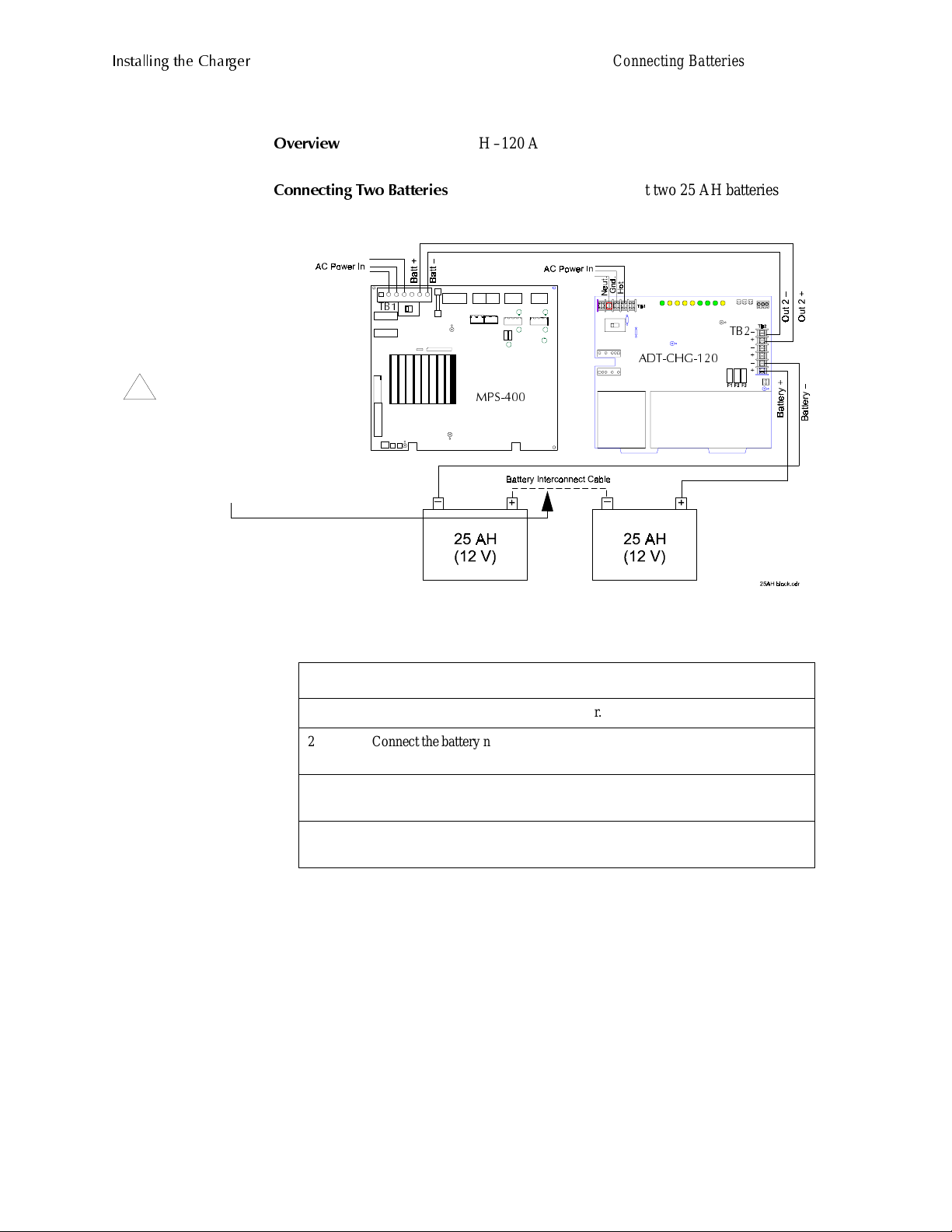
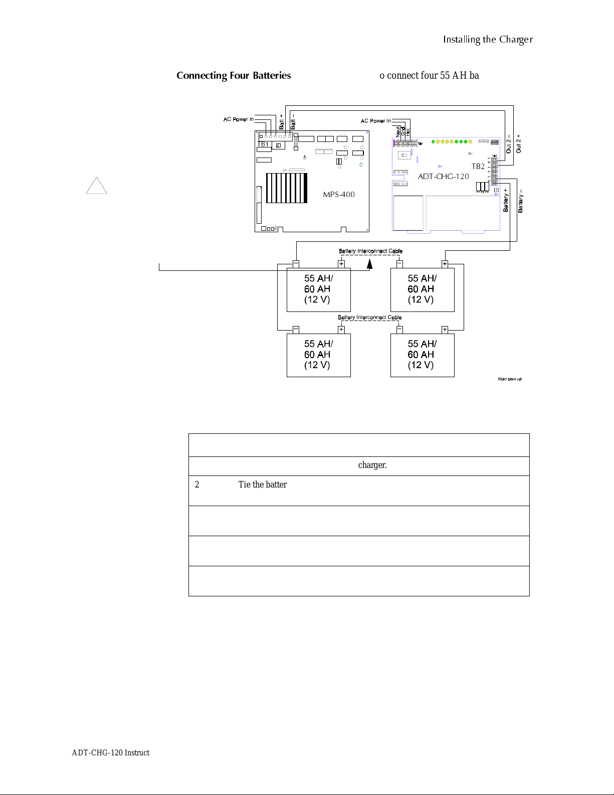
Connecting Batteries to the
Charger How to connect batteries to the charger in two
configurations: using two batteries and using
four batteries.
6
Mounting the Charger How to mount the charger to a CAB-3.
How to mount the charger to a BB-55. 8
Connecting the Charger to
a Load Instructions and illustrations for wiring a charger
to a multiple load and for wiring a charger for a
large system installation.
10
Configuring the Charger Configuring the charger for the following
options:
Delaying loss of AC reporting (DACT); and
Disabling ground fault detection
12
Trouble and Form-C Relay
Connections (Optional) Instructions and illustrations for connecting the
following:
Open Collector Trouble In (JP5)
Trouble Out (JP4)
Master Trouble In (JP6)
Form-C Trouble Relay (TB3)
13
Installing Optional Meters How to install an optional ammeter, voltmeter,
or both. 14
Table 2 Installation Topics