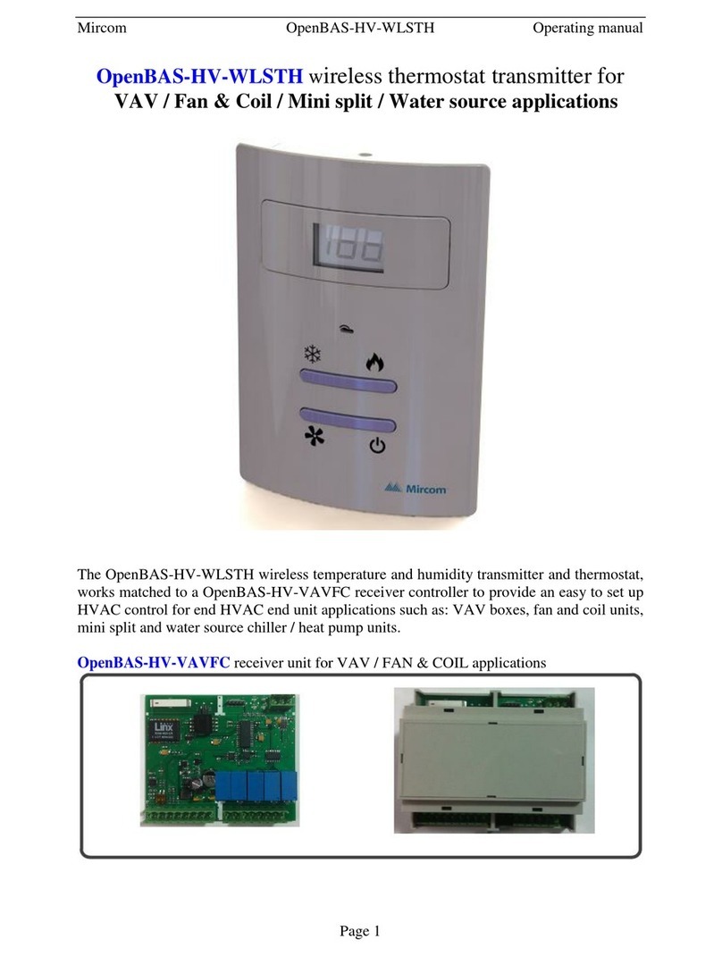
ADTEK Wall-RS485 User manual

HTO
800.
800.
CO/CO Temperature&Humidity Transmitter
2/
Manual
Wall Mount Remote Probe Duct V Type Duct H Type
Rev 1.0
2018-01-01
Rev 1.0
2018-01-01

POWER
400
Indicator
■
Operation Key
■
Interior operation
description
POWER- Power Indicator
blinking and press
Level swap and setting save
40mm
85mm
135mm
1.Don't modify factory setting value
.2 Please make sure the power, input and
output is same with the order
specifications, before installing the
sensor
3 Please note the polarity and refer to the.
wiring diagram before wiring
4 Please isolated power and input for.
avoid electromagnetic interference
Temperature PV adjustment
Temperature force output Don t modify4mA, ’
Display
PVOF-T
PVOF-H
4mA-℃
20mA-℃
4mA-%
20mA-%
PVOF-P
4mA P-
20mA-P
±.20 0℃
±.20 0%
±1500ppm
Press 3 sec when D8+D9D6+D7+
into the first level setting。
CO Temperature&Humidity Transmitter
2/
HTO
Indicator
blinking and press
Press 3 sec when D8+D9D6+D7+
into the second level setting。
Leave setting
Increase key
Decrease key
Dimension
■Connection
■Notice
■
First level setting Press 3 sec when D6+D7+D8+D9 blinking and press:
■
Description Range Init
Humidity PV adjustment
Temperature force output 20 Don t modifymA, ’
Humidity force output Don t modify4mA, ’
Humidity force output 20 Don t modifymA, ’
CO PV adjustment
2
CO force output Don t modify
24mA, ’
CO force output 20 Don t modify
2mA, ’
Factory value
Initialization
Initialization
Initialization
Initialization
Initialization
Initialization
Initialization
Initialization
Initialization
1
Factory value
Factory value
Factory value
Factory value
Factory value
Indicator
D9
D8
D8+D9
D7
D7+D8+D9
D6
D6+D9
D7+D9
D7+D8
Wall-RS485 Temperature&Humidity
Transmitter

ADDR
BAUD
Device address
RS-485 baudrate
RTU
2400 4800 9600、、
、、19200 38400
、57600 115200
1 255~
O81 E81、
N81 N82、
FI-TH
FI-PM
1 10 sec~
1 10 sec~
1
9600
N81
3
1
Function code: 03
0000h
Temperature
0001h Humidity 0.0 ~ 99.9 %
0002h
0005h 0 ~ 5000 ppm
0006h -1500 ~ 1500
001Bh 0 ~ 5000
-50.0 ~ 99.9 C
-20.0 ~ 20.0 C
0003h
0004h
-20.0 ~ 20.0 %
1 ~ 10 Sec
First reference value of LCD back-light for
CO alarm Init 600ppm
2;:
0007h
001Ch
1 ~ 10 Sec
0 ~ 5000
+
SW3 SW2
SW1
+
■
Display Range Init
Rs485 parity check
Temperature & Humidity response time
CO response time
2
Press 3 sec when D6+D7+D8+D9 blinking then release the parameters,
will return to initial factory values.
Initialization
■
RS485 Communication table
■
Address Parameter Range
Function code ,06: 03
Function code: 03
Address Parameter Range
Address Parameter Range
Address Parameter Range
Temperature PV adjustment
Humidity PV adjustment
Temperature & Humidity response time
CO2
C PV adjustmentO2
CO response time
2
Function code ,06: 03
2
Description
Second level setting Press 3 sec when D6+D7+D8+D9 blinking and press:
Second reference value of LCD back-light for
CO alarm Init 1000ppm
2;:
Indicator
D9
D8
D8+D9
D7
D7+D9

1 Temperature and Humidity reading.
Send command:
Address Command Length CRC
01 03 00 00 00 02 C4 0B
Temperature and Humidity value CRC
Return command:
01 03 04 01 0F 01 EF
Note:
Red is Temperature value
01 0F Decimal is 27.1C
01 EF Decimal is 49.5%
2. C readingO2
CRC
01 03 00 05 00 01 94 0B
CRC
01 03 02 03 E8
03 E8 1000ppm
3. CO2PV adjustment
Send command ():C PV adjustment 500ppmO2
Value CRC
01 06 00 06 01 F4
Function code: 03
Parameter
Address Command Length
Address Command Length
Parameter
Send command:
Return command:
C valueO2
Address Command Length
Function code: 03
Note:
Address Command Parameter
Blue is Humidity value
Red is CO value
2
Decimal is
Function code 6: 0
3
RS485 communication connection error troubleshooting
1. Please check USB/322 Comport adress in computer device manager is set correctly.
2. Please check the transmission formats that the system support: N81, N82, E81, O81 are set correctly.
3. Please check the baud rate: 9600 or 19200 or 38400 or 57600 or 115200 are set correctly.
4. Please check RS485 address: 1 to 255 are set correctly.
5. Please check RS485 positive and negative connection of the meter are connected correctly.

DDC
Co / CO /
2% / ℃
Co / CO /
2% / ℃
Indicator
■
Operation Key
■
POWER- Power Indicator
blinking and press
Level swap and setting save
40mm
85mm
135mm
1.Don't modify factory setting value
.2 Please make sure the power, input and
output is same with the order
specifications, before installing the
sensor
3 Please note the polarity and refer to the.
wiring diagram before wiring
4 Please isolated power and input for.
avoid electromagnetic interference
Temperature PV adjustment
Temperature force output Don t modify4mA, ’
Display
PVOF-T
PVOF-H
4mA-℃
20mA-℃
4mA-%
20mA-%
PVOF-CO
4mA CO-
20mA-CO
±.20 0℃
±.20 0%
±150ppm
Press 3 sec when D8+D9D6+D7+
into the first level setting。
blinking and press
Press 3 sec when D8+D9D6+D7+
into the second level setting。
Leave setting
Increase key
Decrease key
Dimension
■Connection
■Notice
■
First level setting Press 3 sec when D6+D7+D8+D9 blinking and press:
■
Description Range Init
Humidity PV adjustment
Temperature force output 20 Don t modifymA, ’
Humidity force output Don t modify4mA, ’
Humidity force output 20 Don t modifymA, ’
CO PV adjustment
CO force output Don t modify4mA, ’
CO force output 20 Don t modifymA, ’
Factory value
Initialization
Initialization
Initialization
Initialization
Initialization
Initialization
Initialization
Initialization
Initialization
Factory value
Factory value
Factory value
Factory value
Factory value
400
80.
25 0.40 0.
Interior operation
description
Indicator
POWER
SW1 SW2
D6
D5 D7
D8
D9
SW3
Indicator
D9
D8
D8+D9
D7
D7+D9
D7+D8
D7+D8+D9
D6
D6+D9
D6+D8
D6+D8+D9
D6+D7
PVOF-CO2±1500ppm
CO PV adjustment
2Initialization
4mA CO- 2
20mA-CO2
CO force output Don t modify
24mA, ’Initialization
Factory value
CO force output 20 Don t modify
2mA, ’Initialization
Factory value
4
Wall-CO / CO /
2Temperature&Humidity
Transmitter

ADDR
BAUD
Device address
RS-485 baudrate
RTU
2400 4800 9600、、
、、19200 38400
、57600 115200
1 255~
O81 E81、
N81 N82、
FI-TH
T-LOLT
1 10 sec~
1
9600
N81
3
■
Display Range Init
RS485 parity check
Temperature & Humidity response time
Description
Second level setting Press 3 sec when D6+D7+D8+D9 blinking and press:
T-HILT
H-HILT
FI-CO
CO-HILT
CO-A1
CO-A2
FI-CO2
CO -HILT
2
CO -A1
2
CO -A2
2
Temperature Low scale
Temperature High scale
Humidity High scale, Don t modify’
CO response time
CO High scale
CO response time
2
C High scaleO2
+
SW3 SW2
SW1
+
Press 3 sec when D6+D7+D8+D9 blinking then release the parameters,
will return to initial factory values.
Initialization
■
RS485 Communication table
■
0000
0001 0 100 0%~ .
0004
-50.0 ~ 100.0 C
-20.0 ~ 20.0℃
0005
0006
-20.0 ~ 20.0 %
- ~150 150 ppm
0002 CO 0 500ppm~
0003 0 5000ppm~
0007 - ~1500 1500 ppm
0008 1 10 sec~
000C - . ~ . ℃50 0 100 0
Low Limit of Temperature
000D - . ~ . ℃50 0 100 0
Function code: 03
Temperature
Humidity
CO
2
Parameter
Address Range
Parameter
Address Range
Temperature PV adjustment
Humidity PV adjustment
CO PV adjustment
CO PV adjustment
2
Temperature & Humidity response time
High Limit of Temperature
- ~50 100 0
- ~50 100 50
0 100~ 100.0
1 10 sec~ 1
0 500~ 500
Set it yourself
1 10 sec~
0 9999~
09
30
1
5000
600
1000
Function code ,06: 03
The LCD backlight is blue when CO 9~31ppm
Set it yourself
Set it yourself
Set it yourself
The LCD backlight is orange when CO 31ppm up
The LCD backlight is blue when CO 600~1000ppm
2
The LCD backlight is orange when CO 1001ppm up
2
Indicator
D9
D8
D8+D9
D7
D7+D9
D7+D8
D7+D8+D9
D6
D6+D9
D6+D8
D6+D8+D9
D6+D7
D6+D7+D9
D6+D7+D8
D6+D7+D8+D9
5

001A
001B
001C
001D
001E LCD toggle switch automatically
0 500ppm~
0 500ppm~
0 5000ppm~
0 5000ppm~
0 1 0:Close 1 Open~:
001F LCD toggle switch automatically, time setting 1 10 sec~
1 CO reading. 2
Send command:
Address Command Parameter Lenth CRC
01 03 00 03 00 01 74 0A
Tempature value CRC
01 03 02 D7 D6
Note:
Red is Co value
2
07 D6 Decimal is 2006ppm
:.Connection description
Protocol: MODBUS RTU
:,,,Parity N81 N82 E81 O81
.Example
3B EA
2.Tempature PV adjustment:
Send Command Tempature PV adjustment 10 0: ( . )
℃
Value CRC
01 06 00 04 00 64 C9 E0
Parameter
Address Range
Return command:
Address Command Lenth
Address Command Parameter
6
The first stage setting of LCD back-light for CO alarm
The second stage setting of LCD back-light for CO alarm
The first stage setting of LCD back-light for CO alarm
2
The second stage setting of LCD back-light for CO alarm
2
. Connection error troubleshooting
1. Please check USB/232 Comport address in computer device manager is set correctly.
2. Please check the device address, baud rate, N81 N82 are set correctly.
3. Please check RS485 positive and negative connection of the meter are connected correctly

POWER
PVOF-T
PVOF-H
4mA-℃
20mA-℃
4mA-%
20mA-%
PVOF-P
4mA P-
20mA-P
±.20 0℃
±.20 0%
±150ppm
SW1 SW2
D9
D8
D8+D9
D7
D7+D9
D7+D8
D7+D8+D9
D6
D6+D9
Sw3
AO+RS485
Temperature & Humidity()
AO+RS485
( y )
CO/ CO Temperature & Humidit
2
47mm
123mm
120mm
18 28
86mm
82mm
47mm
123mm
120mm
18
28
86mm
82mm
47mm
123mm
120mm
18
28
86mm
159mm
Duct V type and H type
800.
±1500ppm
Indicator
■
Operation Key
■
POWER- Power Indicator
blinking and press
Level swap and setting save
Press 3 sec when D8+D9D6+D7+
into the first level setting。
blinking and press
Press 3 sec when D8+D9D6+D7+
into the second level setting。
Leave setting
Increase key
Decrease key
Dimension
■Connection
■
Notice
■
1.Don't modify factory setting value
.2 Please make sure the power, input and output is same with the order specifications, before installing the sensor
3 Please note the polarity and refer to the wiring diagram before wiring.
4 Please isolated power and input for avoid electromagnetic interference.
First level setting Press 3 sec when D6+D7+D8+D9 blinking and press:
■
Display Description Range InitIndicator
Temperature PV adjustment
Temperature force output Don t modify4mA, ’
Humidity PV adjustment
Temperature force output 20 Don t modifymA, ’
Humidity force output Don t modify4mA, ’
Humidity force output 20 Don t modifymA, ’
CO PV adjustment
CO PV adjustment
2
CO / CO force output Don t modify
24mA, ’
CO/ CO force output 20 Don t modify
2mA, ’
Initialization
Initialization
Initialization
Initialization
Initialization
Initialization
Initialization
Initialization
Initialization
Factory value
Factory value
Factory value
Factory value
Factory value
Factory value
7
Duct V type and H type CO / CO /
2Temperature&Humidity Transmitter
Remote Probe CO / CO2/ Temperature&Humidity Transmitter
Interior operation
description
Indicator
Remote Probe

0000
0001 0.0 ~ 99.9 %
0006
-50.0 ~ 99.9 C
-150 150~
0007
001B
1 10 sec~
0 2000 5000 10000 ppm~、、
According to order()
0002
0003
001C
-20.0 ~ 20.0 C
-20.0 ~ 20.0%
1 ~ 10 sec
0004
0005 CO
0 100 300 500 According to order~、、( )
0 100 300 500 ppm~、、
()According to order
0 2000 5000 10000 According to order~、、 ( )
0 2000 5000 10000 ppm~、、
()According to order
0 100 300 500 ppm~、、
()According to order
1 10 sec~
-1500 1500~
■Second level setting Press 3 sec when D6+D7+D8+D9 blinking and press:
ADDR
BAUD
Device address
RS-485 baudrate
RTU
2400 4800 9600、、
、、19200 38400
、57600 115200
1 255~
O81 E81、
N81 N82、
FI-TH
T-LOLT
1 10 sec~
1
9600
N81
3
Display Range Init
RS485 parity check
Temperature & Humidity response time
Description
T-HILT
FI-PM
PPM-A1
PPM-A2
Temperature Low scale
Temperature High scale
CO response time
The LCD backlight is blue when CO 9~31ppm
The LCD backlight is orange when CO 31ppm up
- ~50 100 0
- ~50 100 50
1 10 sec~ 1
1 10 sec~ 1
Set it yourself 09
Indicator
D9
D8
D8+D9
D7
D7+D9
D7+D8
D7+D8+D9
D6
D6+D9
+
SW3 SW2
SW1
+
Press 3 sec when D6+D7+D8+D9 blinking then release the parameters,
will return to initial factory values.
Initialization
■
RS485 Communication table
■
Function code: 03
Function code ,06: 03
Function code: 03
Function code ,06: 03
Address Parameter Range
Temperature
Humidity
Address Parameter Range
Temperature & Humidity response time
Temperature PV adjustment
Humidity PV adjustment
Address Parameter Range
CO2
Address Parameter Range
C PV adjustmentO2
C PV adjustmentO
CO response time
2
CO response time
First reference value of LCD back-light for
CO alarm Init 9ppm;:
First reference value of LCD back-light for
CO alarm Init 600ppm
2;:
Second reference value of LCD back-light for
CO alarm Init 30ppm;:
Second reference value of LCD back-light for
CO alarm Init 1000ppm
2;:
8
CO response time
2
The LCD backlight is blue when CO 600~1000ppm
2Set it yourself 600
Set it yourself
Set it yourself
30
1000
The LCD backlight is orange when CO2 1001ppm up

1 Temperature and Humidity reading.
Send command:
Address Command Length CRC
01 03 00 00 00 02 C4 0B
Temperature and Humidity value CRC
Return command:
01 03 04 01 0F 01 EF
Note:
Red is Temperature value
01 0F Decimal is 27.1C
01 EF Decimal is 49.5%
2. C readingO2
CRC
01 03 00 05 00 01 94 0B
CRC
01 03 02 03 E8
03 E8 1000ppm
3. CO2PV adjustment
Send command ():C PV adjustment 500ppmO2
Value CRC
01 06 00 06 01 F4
Function code: 03
Parameter
Address Command Length
Address Command Length
Parameter
Send command:
Return command:
C valueO2
Address Command Length
Function code: 03
Note:
Address Command Parameter
Blue is Humidity value
Red is CO value
2
Decimal is
Function code 6: 0
9
RS485 communication connection error troubleshooting
1. Please check USB/322 Comport adress in computer device manager is set correctly.
2. Please check the transmission formats that the system support: N81, N82, E81, O81 are set correctly.
3. Please check the baud rate: 9600 or 19200 or 38400 or 57600 or 115200 are set correctly.
4. Please check RS485 address: 1 to 255 are set correctly.
5. Please check RS485 positive and negative connection of the meter are connected correctly.
Table of contents
Other ADTEK Transmitter manuals
Popular Transmitter manuals by other brands

Emerson
Emerson Rosemount 5408 quick start guide

Infineon
Infineon AN234970 manual
Ashcroft
Ashcroft GXLdp Installation and operating instructions
ClearSounds
ClearSounds QLINK operating manual
M-system
M-system W2CFG quick start guide
Dwyer Instruments
Dwyer Instruments Dwyer AVUB Series Specifications-installation and operating instructions
