Infineon AN234970 User manual

Application Note Please read the Important Notice and Warnings at the end of this document 002-34970 Rev. **
www.infineon.com page 1 of 36 2022-05-03
AN234970
Foreign object detection tuning guide for
wireless power transmitters
Applicable to WLC ICs
About this document
Scope and purpose
The wireless charger (WLC) power transmitter solution reference board is a highly integrated wireless solution
with Type-C power delivery (PD).
This application note is a guide to configure the foreign object detection (FOD) parameters required for custom
designs based on the WLC power transmitter reference design.
Intended audience
Experts who customize designs based on REF_WLC_TX15W_C1-based wireless power transmitters.

Application Note 2 of 36 002-34970 Rev. **
2022-05-03
Foreign object detection tuning guide for wireless power transmitters
Applicable for WLC ICs
Table of contents
Table of contents
Table of contents............................................................................................................................ 2
Acronyms/Abbreviations ................................................................................................................. 3
1Introduction .......................................................................................................................... 4
1.1 Document structure................................................................................................................................4
2Getting started ...................................................................................................................... 5
2.1 FOD mechanism ......................................................................................................................................5
2.1.1 FOD before power transfer ................................................................................................................5
2.1.2 FOD during power transfer ................................................................................................................7
2.1.3 FOD using pre- and in-power transfer methods ...............................................................................9
3FOD parameter tuning ...........................................................................................................14
3.1 Tuning objectives ..................................................................................................................................14
3.2 Required tools .......................................................................................................................................15
3.3 Hardware setup.....................................................................................................................................16
3.4 Q factor scaling factor tuning process..................................................................................................17
3.4.1 Q factor scaling and threshold tuning process...............................................................................18
3.4.2 Q factor-based FOD tuning ..............................................................................................................19
3.5 Resonance frequency scaling factor and threshold tuning process ...................................................20
3.5.1 Resonance frequency scaling and threshold tuning process.........................................................20
3.5.2 Resonance frequency-based FOD tuning........................................................................................23
3.6 System power loss curve coefficient tuning.........................................................................................23
3.6.1 Data collection and system loss curve coefficient calculation ......................................................23
3.6.2 Power loss-based FOD tuning..........................................................................................................25
4FOD functionality verification.................................................................................................29
5Checklist for tuning operation ................................................................................................30
Appendix I –Finding signal strength ................................................................................................31
Appendix II –Received power offset.................................................................................................32
Appendix III –Enabling UART logs using Wireless Charging Configuration Utility ..................................33
References....................................................................................................................................34
Revision history.............................................................................................................................35

Application Note 3 of 36 002-34970 Rev. **
2022-05-03
Foreign object detection tuning guide for wireless power transmitters
Applicable for WLC ICs
Acronyms/Abbreviations
Acronyms/Abbreviations
Table 1 Acronyms/Abbreviations
Acronym/Abbreviation
Definition
USB PD
Universal serial bus power delivery
DUT/EUT
Device under test/Equipment under test
TX
Transmitter
RX
Receiver
BPP
Baseline power profile
EPP
Extended power profile
TPR
Test power receiver
ASK
Amplitude shift keying
FSK
Frequency shift keying
WPT
Wireless power transfer
CE
Control error
CEP
Control error packet
FO
Foreign object
OVP
Overvoltage protection
OCP
Overcurrent protection
UVP
Undervoltage protection
FOD
Foreign object detection
PCB
Printed circuit board
EMI
Electromagnetic interference
NTC
Negative temperature coefficient
UART
Universal asynchronous receiver-transmitter
LED
Light-emitting diode
RPP
Reported power packet
RP
Reported power
NAK
Not acknowledge packet (FSK response)
ACK
Acknowledge packet (ASK response)
RF
Resonance frequency

Application Note 4 of 36 002-34970 Rev. **
2022-05-03
Foreign object detection tuning guide for wireless power transmitters
Applicable for WLC ICs
Introduction
1Introduction
This application note serves as a guide to tune the FOD parameters for optimal power transmitter performance.
The Wireless Charging Configuration Utility enables the user to configure FOD parameters. Refer to [8] and [9]
for more details on the product reference design, referred to as “reference design” in this document. Please
contact the Infineon sales team for any additional support.
1.1 Document structure
▪Section 2 [Getting started] describes the FOD mechanism recommended by the Qi Standard and the WLC
power transmitter approach for the FOD mechanism. Advanced users may skip this section.
▪Section 3 [FOD parameter tuning] describes the data collection, configuration parameter calculation, and
updating the WLC power transmitter using the Wireless Charging Configuration Utility. This section gives the
following details:
oQ factor scaling factor and threshold tuning: This section defines the process for configuring
the scaling factor and thresholds for a Q factor-based FOD approach.
oResonance frequency scaling factor and threshold tuning: This section defines the process for
configuring the scaling factor and thresholds for a RF-based FOD approach.
oSystem power loss curve coefficient tuning: This section defines the tuning process to
estimate and configure the power loss parameters. These parameters shall be programmed to
the WLC power transmitter for aiding FOD using power loss measurements.
▪Section 4 [FOD functionality verification] refers to the post-tuning process to validate the configurations
and confirm the performance of the new settings the user makes.
▪Section 5 [Checklist for tuning operation] is a checklist of items to be ensured during the tuning
operation.
▪The appendices contain normative information for users.

Application Note 5 of 36 002-34970 Rev. **
2022-05-03
Foreign object detection tuning guide for wireless power transmitters
Applicable for WLC ICs
Getting started
2Getting started
The WLC power transmitter provides Qi-compliant FOD features. Refer to the FOD chapter in the Qi Standard
for further details (see [1]and [4]). The following sections discuss the WLC power transmitter implementation
of the FOD functionality.
2.1 FOD mechanism
The Qi Standard defines two mechanisms for FOD:
1. FOD before power transfer or pre-power transfer method
2. FOD during power transfer or in-power transfer method
2.1.1 FOD before power transfer
The pre-power transfer FOD method has the following mechanisms to detect a FO before power transfer
between Rx and Tx starts:
1. Q factor FOD (FOD/qf)
2. Resonance frequency FOD (FOD/rf)
The receiver sends FOD/rf and/or FOD/qf packets during the negotiation phase. The Tx responds to these
packets with an ACK packet if no FO is found and with a NAK packet if a FO is found. The Rx measures the
Q factor and resonance frequency values with a standard MP-A1 coil. The transmitter may measure Q factor
and resonance frequency values different from the receiver-reported values, as it may have a different coil. A
scaling factor is used to convert the receiver-reported Q factor and resonance frequency values to those
equivalent to the transmitter coil.
The scaling factor is a function of the shielding material and friendly materials present in the Rx. This is derived
by looking at the relation between the Q factor and resonance frequency devised by the MP-A1 coil and the
experimentally measured Q factor and resonance frequency values. The scaling factors for Q factor and
resonance frequency measurements can be unique. The FOD/qf packets are sent by all extended power profile
(EPP) receivers compliant with Qi 1.2 or above. The FOD/rf packets are sent by all EPP receivers compliant with
Qi 1.3 or above.

Application Note 6 of 36 002-34970 Rev. **
2022-05-03
Foreign object detection tuning guide for wireless power transmitters
Applicable for WLC ICs
Getting started
Q FO detection threshold
Test Receiver
with FO
Test Receiver without FO
Figure 1 FOD mechanism based on Q factor
Q factor: This involves measurement of the Q factor when an EPP TPR is placed on the interface surface of the
transmitter. All the EPP TPRs report the reference Q factor measured with a MP-A1 transmitter coil. The
transmitter controller needs to apply a scaling factor to derive the reference Q factor value with its transmitter
coil (i.e., the coil considered for transmitter design). The measured Q factor by the WLC power transmitter
needs to be compared with the Q FO detection threshold, which is calculated from the scaled reference
Q factor. The comparison of the measured Q factor with Q FOD threshold determines the FO presence on the
interface surface before power transfer starts. The FO is detected if the difference between measured and
receiver-reported reference Q factor (FOD/qf packet) is less than the threshold. The measured Q factor includes
a scaling factor [7].
If Qrep is the receiver-reported Q factor and Qscl is the scaled Q factor, then,
Qrep = Sfactor * Qscl
Equation 1
Where Sfactor is the scaling factor for the custom transmitter. FO detection occurs when:
Qmeas < Qthreshold
Equation 2
Where Qthreshold is the threshold Q factor and Qmeas is measured Q factor. The measurement of Qthreshold and its
relation with Qscl is explained in [11].
Resonance frequency: This involves measurement of the resonance frequency (RF) when an EPP TPR is placed
on the interface surface of the Tx. The reported RF is scaled to the Tx coil type by using a scaling factor. The
measured RF is compared with the scaled RF and if the shift (difference) in RF is greater than the threshold, FO
presence is confirmed.
The resonance frequency (in Hz) is derived from the supporting data as follows:
Fres = (2 * FOD/rf supporting data) + 72
Equation 3
Fscaled = ScalingFactor * Fres
Equation 4
Fthreshold = Fscaled * Threshold_percent
Equation 5

Application Note 7 of 36 002-34970 Rev. **
2022-05-03
Foreign object detection tuning guide for wireless power transmitters
Applicable for WLC ICs
Getting started
Where Fres is the reported RF, Fscaled is the scaled RF, Fthreshold is the threshold RF. Threshold_percent and
ScalingFactor are configurable from the Wireless Charging Configuration Utility.
Test Receiver
with FO1
Test Receiver with FO2
Test Receiver1 without FO
Test Receiver2
without FO
Scaled RF
FO present
FO present
NO FO
Higher
threshold of RF
Lower
threshold of RF
Figure 2 Resonance frequency-based FOD
The FO is detected if the difference between measured and scaled reference resonance frequency is greater
than the threshold. “ScalingFactor” and “Threshold_percent” are configurable from the wireless charging
configuration utility.
In case of a FOD, the Tx responds to the FOD/rf or FOD/qf packets with a NAK packet leading to immediate
power disconnect. The communication is re-established only after the object is removed. Refer to the user
manual for LED user interface for FO detection.
2.1.2 FOD during power transfer
The power loss FOD mechanism involves measuring the transmitter power periodically during power transfer
and comparing the measured power with the loss curve estimates given by the receiver. To improve the
reliability and accuracy of FOD, additional methods are introduced by the WLC power transmitter.

Application Note 8 of 36 002-34970 Rev. **
2022-05-03
Foreign object detection tuning guide for wireless power transmitters
Applicable for WLC ICs
Getting started
Figure 3 Typical power loss measurement with power delivery range
System power loss: The FO is detected if the measured system power loss exceeds the system power loss
threshold value. Refer to [2] for more details on the FOD techniques recommended by the Qi Standard.
Accurate FOD requires reference to the power loss calibrated parameter data for a given hardware design and
interface surface height (Z-axis). This reference calibration data is required to compensate for the power loss
balance deviations induced by the system. The WLC power transmitter system power loss varies with
transmitter power delivery range, receiver device coupling factor, temperature, etc. Section 3.5 shows a typical
power loss measurement over the power delivery range and the respective loss correction curve. This is a
typical behavior of loss correction along with the system power losses.
Power loss calculations are initiated on receipt of a RPP. The calibrated transmitter power is derived from RP
value as follows:
PTx_calib = a* PRx2+ b* PRx + c
Equation 6
Where a,b and c are the system power loss curve coefficients. These coefficients are unique for each power
transfer mode as follows:
•EPP 15 watt (EPP15W): Representative test power receiver (TPR) is TPR#MP3. The load power typically
ranges from 300 mW to 15 W.
•EPP 5 watt (EPP5W): Representative TPR is TPR#7. The load power typically ranges from 300 mW to 5 W.
•Baseline power profile (BPP): Representative TPR is TPR#5. The load power typically ranges from 300 mW to
5 W.
A system power loss curve is used to account for the losses from the transmitter. The power loss equation
relates the transmitter power and the reported power as follows:
Ploss = PTx –PTx_calib
Equation 7
Where PTx_calib is derived from Equation 6. The criteria for FO presence are:
Ploss >= PThreshold
Case 1
Ploss >= PThreshold_max
Case 2
Where PThreshold and PThreshold_max are configuration parameters, and:
PThreshold_max > PThreshold
-150
-100
-50
0
50
100
150
200
250
300
02000 4000 6000 8000 10000 12000 14000 16000 18000 20000
Losses (mW)
PRx (mW)
Measured system power loss
System Power Loss Curve
CorrectedLosses

Application Note 9 of 36 002-34970 Rev. **
2022-05-03
Foreign object detection tuning guide for wireless power transmitters
Applicable for WLC ICs
Getting started
Case 1 represents the region
1
and Case 2 represents the region
2
in Figure 4.
FO Threshold
Threshold_max
1
2
Receiver
without FO
FO present with high power dissipation in FO.
FO detected.
Receiver with FO2
Receiver with FO1
Figure 4 FOD mechanism based on system power loss
The thresholds for FOD can be configured. Refer to Section 3.6 for tuning thresholds for power loss-based FOD.
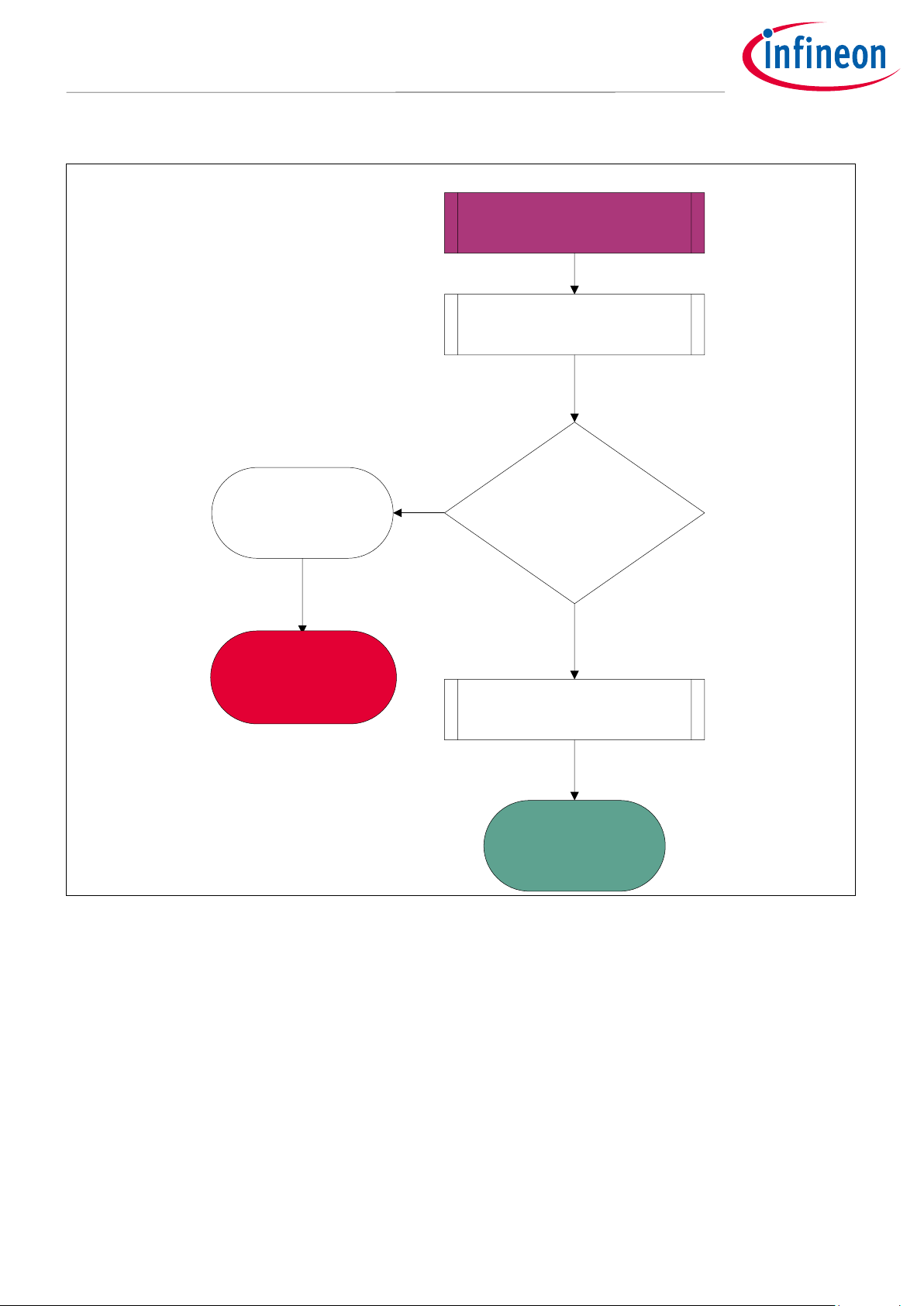
2.1.3 FOD using pre- and in-power transfer methods
Figure 5 illustrates the free-air Q factor FOD mechanism. The object detection mechanism identifies the
placement of an object and initiates the Qi communication stack, which involves pre- and in-power transfer
FOD mechanisms. Pre-power transfer data is measured by Tx during the analog pings. Upon object detection,
the free-air FOD method finds FOs. If the device is a valid receiver, it proceeds to the identification and
configuration phases. The FOD/qf packet is exchanged for an EPP device optimizing the FOD for EPP devices.
The WLC’s patented Q factor-based FOD mechanism identifies the FOs already present or while entering the
interface field before power transfer starts
A power loss-based FOD mechanism identifies FOs, which may enter the interface surface after power transfer.
The WLC power transmitter uses a combination of both Q factor and power loss-based mechanisms for optimal
and efficient FOD in BPP and EPP devices. Refer to the user manual for UI indication for FOD.

Application Note 10 of 36 002-34970 Rev. **
2022-05-03
Foreign object detection tuning guide for wireless power transmitters
Applicable for WLC ICs
Getting started
Measure the
open air Q-factor
Is the
measured Q less
than the
open Air FO
threshold?
No
Yes FO detected by
Q-factor
Wait till the object
is removed, LED UI
indication
Proceed to
digital ping
1
BPP and EPP devices
Receiver / FO
arrival detection
Figure 5 Procedure for free-air Q factor FOD in BPP and EPP devices
Application Note 11 of 36 002-34970 Rev. **
2022-05-03
Foreign object detection tuning guide for wireless power transmitters
Applicable for WLC ICs
Getting started
Figure 6 illustrates the FOD using Q factor mechanism:
Continued from 1
EPP device
Process the FOD/qf packet
from receiver
Is the
measured Q less than
the
reference threshold ?
NAK the FOD/qf
packet indicating
an FO Yes
Valid TPR/Smart phone.
ACK the FOD/qf packet
No
Proceed to next
phase
Wait till the object
is removed, LED UI
indication
Figure 6 Procedure for Q factor FOD in EPP devices

Application Note 12 of 36 002-34970 Rev. **
2022-05-03
Foreign object detection tuning guide for wireless power transmitters
Applicable for WLC ICs
Getting started
Figure 7 illustrates FOD using the resonance frequency mechanism:
Continued from 1
EPP device
Process the FOD/rf packet
from receiver
Is the
difference in RF
measurements
greater than
threshold?
NAK the FOD/rf
packet indicating
an FO Yes
Valid TPR/Smart phone.
ACK the FOD/rf packet
No
Proceed to next
phase
Wait till the object
is removed, LED UI
indication
Figure 7 Procedure for resonance frequency FOD on EPP devices

Application Note 13 of 36 002-34970 Rev. **
2022-05-03
Foreign object detection tuning guide for wireless power transmitters
Applicable for WLC ICs
Getting started
BPP and EPP devices
In power transfer
phase
Is the load
stable (load
transition)?
Yes
No
Calculate the
system power loss
Wait for load
to stabilize.
Is the loss
exceeding the
threshold_
max?
No
Yes
Is the loss
exceeding the
threshold but under
Threshold
_max?
Yes
No
Continue the power
transfer.
FO detected with
maximum power loss.
FO detected with
power loss.
Wait till the object
is removed, LED UI
indication
Are the user
configured
retries
complete?
Yes
No
Figure 8 Procedure for FOD using power loss mechanism on EPP and BPP devices
As shown in Figure 8, the system power loss measurements start only after a stable load condition. This is
ensured by checking the control error packet (CEP) value.

Application Note 14 of 36 002-34970 Rev. **
2022-05-03
Foreign object detection tuning guide for wireless power transmitters
Applicable for WLC ICs
FOD parameter tuning
3FOD parameter tuning
FOD parameter tuning is required when the reference design of the WLC power transmitter is changed. The
following changes from the WLC power transmitter reference design will result in a need to retune the FOD:
1. Transmitter coil used in the design
2. Change in any shielding or packaging of the transmitter coil
3. Spacing between coil and interface surface (Z-height)
These lead to changes in the Q factor and/or resonance frequency and/or system power loss measurements.
Tuning FOD by updating the configuration parameters optimizes the FOD functionality for custom designs.
FOD parameter tuning includes the process of data collection, calculating the appropriate parameters, and
updating these parameters in the Wireless Charging Configuration Utility.
Data collection and calculation of parameter values use the FOD_TuningGuide_Calculator.xlsx as a supporting
document. This tuning calculator provides the following worksheets that require user input:
•SystemPowerLoss_data: Input data for power loss FOD parameter calculations is collected here. The
coefficients calculated here are used for configuring the WLC power transmitter.
•QF Scaling Factor Calc: Q factor tuning data is collected in the “User Inputs” section in this page. The
calculations section gives the parameter values for Q factor tuning based on user inputs.
•RF Scaling_Threshold Calc: The RF-based data is collected in the “User Inputs” section. The scaling
factor and threshold frequency are auto-generated based on the user data.
Wireless Charging Configuration Utility will save the configurations to the WLC power transmitter. These
calculations are taken from FOD_TuningGuide_Calculator.xlsx.
The tuning process requires a WPC-approved compliance tester tool setup. The following sections discuss the
tools required and the steps to prepare the setup. Use FOD_TuningGuide_Calculator.xlsx to enter the data from
the setup to auto-generate the tuning parameters.
3.1 Tuning objectives
The following are the desired objectives for optimal FOD system performance:
•Scaling factor and threshold tuning for FOD using Q factor
•Scaling factor and threshold tuning for FOD using resonance frequency
•System power loss curve coefficient tuning
As discussed in section 2.1.2, the system power loss curve coefficients relate the reported receiver power to the
calibrated transmitter power and hence improve the reliability of the FOD mechanism. The reported Q factor
and resonance frequency is measured using a MP-A1 transmitter coil. However, the transmitter may have any
other coil in its design and so the reference values of Q factor have to be scaled (or converted) to the
corresponding coil type. The scaling factor is a conversion constant factor to calculate Q factor values for the
transmitter designed without a MP-A1 coil. Refer to [2] for more details on the Qi Standard FOD mechanisms.
Application Note 15 of 36 002-34970 Rev. **
2022-05-03
Foreign object detection tuning guide for wireless power transmitters
Applicable for WLC ICs
FOD parameter tuning
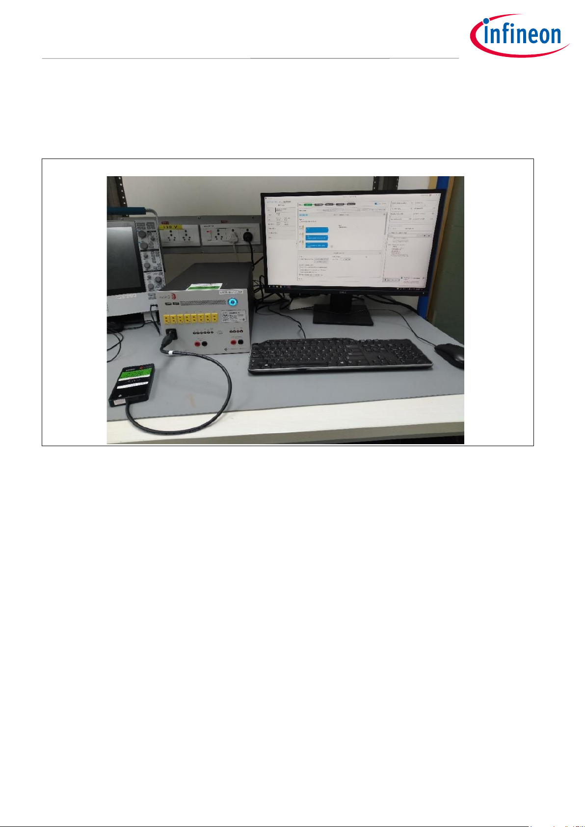
3.2 Required tools
The following tools are required for the tuning process:
1. Custom design power transmitter board.
Figure 9 WPC-approved reference compliance tester
2. WPC-approved compliance tester. The user may approach the WPC’s authorized test labs (ATLs) [5]
in case of unavailability of the compliance tester tools. The user should refer to the WPC member
login page for details of the list of WPC-approved compliance testers. The following accessories are
available along with the software tool.
•Test power receivers (TPRs): For the tuning process the following TPRs are needed:
i. TPR#MP1A
ii. TPR#MP1B
iii. TPR#MP1C
iv. TPR#MP4
v. TPR#MP3
vi. TPR#1A
vii. TPR#7
viii. TPR#5
•FO frame.
•Glass weight: For making the TPR stable.
Application Note 16 of 36 002-34970 Rev. **
2022-05-03
Foreign object detection tuning guide for wireless power transmitters
Applicable for WLC ICs
FOD parameter tuning
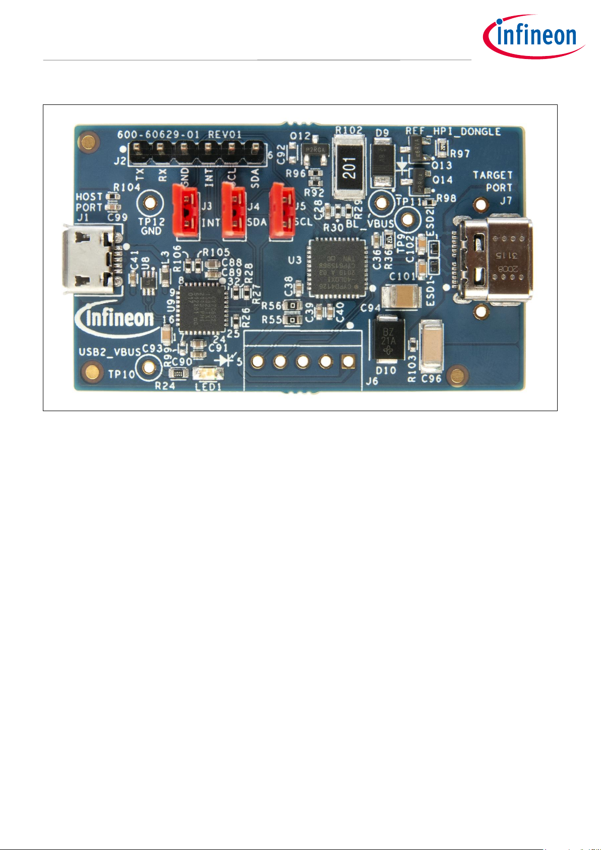
3. USB-UART device for capturing UART logs from WLC power transmitter board.
Figure 10 Infineon USB to UART device
4. Tera term or Putty or any serial communication-based PC tool for capturing UART logs from the
WLC power transmitter board (ensure that the PC tool used for data logging is capable of
processing UART data at 1,000,000 baud with minimal losses).
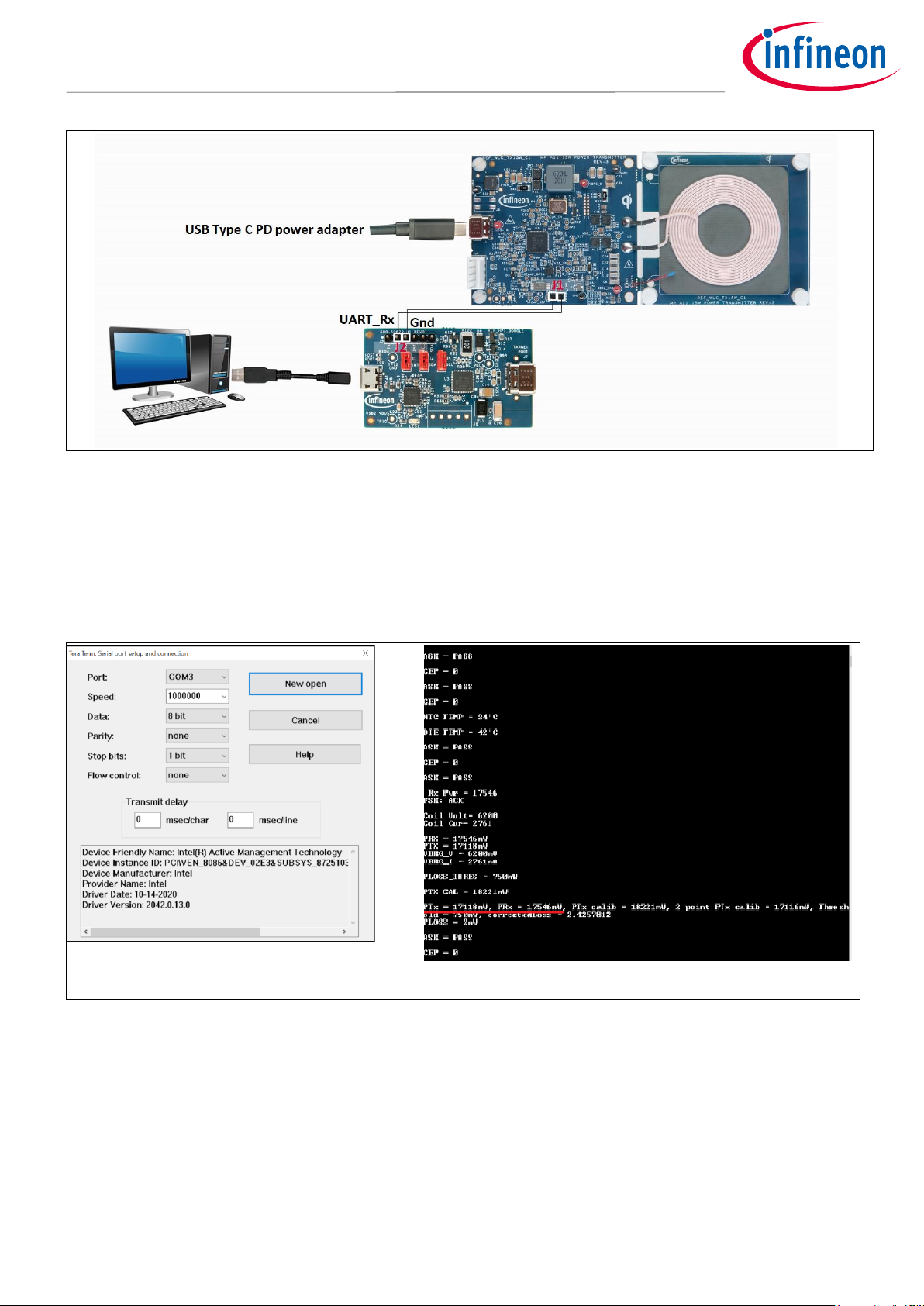
3.3 Hardware setup
1. Enable the UART debugs from the Wireless Charging Configuration Utility. See Appendix III for
details.
2. Connect the UART Tx line from the power transmitter board to the UART Rx line of the USB-UART
device.
3. Connect the ground of the transmitter board to the USB–UART device.
Application Note 17 of 36 002-34970 Rev. **
2022-05-03
Foreign object detection tuning guide for wireless power transmitters
Applicable for WLC ICs
FOD parameter tuning
Figure 11 UART connections with PC
4. Open the serial communication terminal (such as Minicom/Tera Term/Putty) and set the baud rate
to 1000000.
5. Leave the rest of the UART settings as default.
6. Power on the transmitter board to see UART logs (human-readable ASCII characters) on the serial
communication tool (UART interface).
Default Tera Term screen
UART log on Tera Term
Figure 12 Tera Term debug screen and log UI for reference
3.4 Q factor scaling factor tuning process
Use the “QF Scaling Factor Calc” page in FOD_TuningGuide_Calculator.xlsx as the supporting document for this
section. Update the “User Inputs” section with the measured and reported Q-Factor values. The measured and
reported Q-Factor values can be taken from the UART logs of WLC power transmitter. The “Calculations”
section in the “QF Scaling Factor Calc” page, generates the scaled Q–factor values. Q Factor method is based on
TPRs with least friendly metals, for instance, standard Qi compliance TPRs like TPR#MP3, TPR#7 and TPR with
high friendly metals like TPR#MP4.

Application Note 18 of 36 002-34970 Rev. **
2022-05-03
Foreign object detection tuning guide for wireless power transmitters
Applicable for WLC ICs
FOD parameter tuning
3.4.1 Q factor scaling and threshold tuning process
The Q factor scaling derives the reference Q factor for the WLC power transmitter from the receiver-reported
reference Q factor. The WLC power transmitter uses two scaling factors.
•Q-high scale factor: Used for scaling the reference Q factor by the TPRs without friendly metals. The EPP
TPRs, without friendly metal, will report the reference Q factor greater than 100.
•Q-low scale factor: Used for scaling the reference Q factor by the TPRs with friendly metals. The EPP
TPRs, with friendly metal, will report the reference Q factor less than 100.
The following steps should be followed to tune the Q scaling factor:
1. Capture the receiver-reported reference Q factor for all the EPP TPRs on the “QF Scaling Factor Calc”
page of the supporting document under the “Q factor Scaling with TPRs without Friendly Metals” table
for the following TPRs:
a. TRP#MP3
b. TPR#MP4
c. TPR#7
See Figure 13 for the UART logs for receiver-reported reference Q factor.
2. Capture the measured Q value by the WLC power transmitter with all the EPP TPRs listed below. Ensure
no foreign object is present on the interface surface during these measurements. See Figure 13 for
UART logs for the WLC-measured Q factor.
Figure 13 UART logs for receiver-reported and WLC power transmitter measured Q factor
3. Record high scaling factor from “QF Scaling Factor Calc” and update the Wireless Charging
Configuration Utility parameters. Refer to section 3.4 for more details.
4. Repeat Steps 1 through 3 with Q factor scaling with TPRs without friendly metals.

Application Note 19 of 36 002-34970 Rev. **
2022-05-03
Foreign object detection tuning guide for wireless power transmitters
Applicable for WLC ICs
FOD parameter tuning
5. Enter the measured and reported Q factor values in the respective cells in the “QF Scaling Factor Calc”
page. The scaling factor is calculated in this page.
Figure 14 User input section in “QF Scaling Factor Calc” page
The next section explains the usage of the parameters generated in the supporting document.
3.4.2 Q factor-based FOD tuning
Figure 15 View of Q factor settings configuration tool
Table 2 Q factor configuration setting parameters
S. no.
Parameter
Description
1
Q factor and resonance
frequency FOD enable
Enables Q factor measurement for FOD.
Enabled by default.
2
Open air coil Q
Open air Q factor value. Measured by LCR meter without
anything on the Tx
Default value is 70
3
Coil Q measurement tolerance
(%)
Coil Q measurement tolerance percentage of coil open
air Q value.
Default value is 5

Application Note 20 of 36 002-34970 Rev. **
2022-05-03
Foreign object detection tuning guide for wireless power transmitters
Applicable for WLC ICs
FOD parameter tuning
S. no.
Parameter
Description
4
Prepower Q FOD threshold (%)
Q factor threshold for FO detection when there is no
communication.
Default value is 30.
5
No response digital ping retry
count
Object detected with no communication/response to
digital ping will retry for initiating communication.
Retry count expiry will enter into idle state.
Default value is 2.
6
Q MPA1 scale factor for Rx with
no friendly metals (%)
Scaling factor for TPRs with higher Q measurements.
Default value is 40%.
7
Q MPA1 scale factor for Rx with
friendly metals (%)
Scaling factor for TPRs with lower Q measurements.
Default value is 75%.
3.5 Resonance frequency scaling factor and threshold tuning process
The resonance frequency method is an improvement of the pre-power transfer of the FOD mechanism using
Q factor. The experiments show that the resonance frequency-based FO is more efficient on Rx with friendly
metals, like smartphones, tablets and so on. A reference TPR for such devices is TPR#MP4. Hence the scaling
factor and threshold tuning process is based on the TPR#MP4.
Refer to section 3.2 for required tools and section 3.3 for setting up the hardware. Further steps for RF tuning
are applicable for TPR#MP4.
3.5.1 Resonance frequency scaling and threshold tuning process
The process involves capturing the measured resonance frequency values from the UART logs (as shown in
Figure 16) or alternatively use the digital signal oscilloscope or LCR Meter [7].This section elaborates on using
system measurements available from the UART logs as shown below:
Table of contents
Other Infineon Transmitter manuals


Popular Transmitter manuals by other brands

Motorline professional
Motorline professional M170 User& installer's manual

Obsolete
Obsolete DP-10 operating instructions

Sunstech
Sunstech FMT130 manual

APG
APG PT-500 Series user manual

Eldat
Eldat Easywave RT24 Series operating instructions

VERIS INDUSTRIES, INC.
VERIS INDUSTRIES, INC. AA10 Series installation guide


