261242008L1-5, Issue 2 61242008L1-5B
2. INSTALLATION
After unpacking the unit, immediately inspect if for
shipping damage. If damage is discovered, file a
claim with the carrier, then contact ADTRAN
Customer Service (see Warranty and Customer
Service).
Before installing the HR4, remove all plug-in cards
that may have been shipped in the unit.
NOTE
Thesearestatic-sensitiveunits andshould be
handledusingtheappropriateESDprotective
measures.
To remove the cards, grasp the metal edge at the left
side of the card and pull outward. This will unseat the
unit from its connector. Temporarily place the unit in
a protected area.
The unit mounting flanges have two sets of mounting
holes. Position the unit and align the mounting holes
with the wall screws attached, using the mounting
template. The template attaches to the wall by a tape
strip located across the top of the template. Remove
the template after use.
No clearance is required on the top or the sides of the
unit. Two inches must be allowed below the unit for
cabling.
After the screws have been secured, place the unit
over the screw heads and pull the base gently
downward to position the screw heads on the narrow
slot of the keyhole. If necessary, the screws may be
tightened to further secure the unit.
In the initial installation, it is not necessary to equip
all the slot locations with plug-in cards. The unit can
be equipped with up to four ADTRAN HTU-R
transceivers. These units should be loaded into slots
one through four. The DS-1 and HDSL loop wiring is
made on the corresponding backplane connector.
32
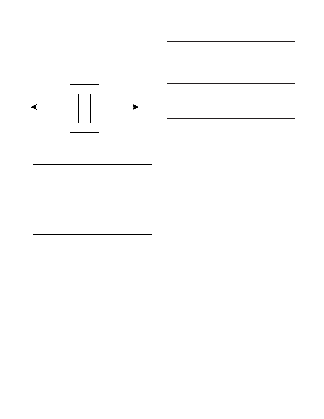
1
Pin 1 Frame Ground
Pin 2 -48V Return
Pin 3 -48V Supply
Figure 2. P5 Backplane Barrier Strip
Connections
Backplane Connections
Connection Locations
The shelf has a backplane containing four 56-pin
connectors. These connectors are interconnected with
printed circuit copper traces. Power and ground
connections are available on a three-position barrier
strip (P5) located on the backplane (see Figure 2).
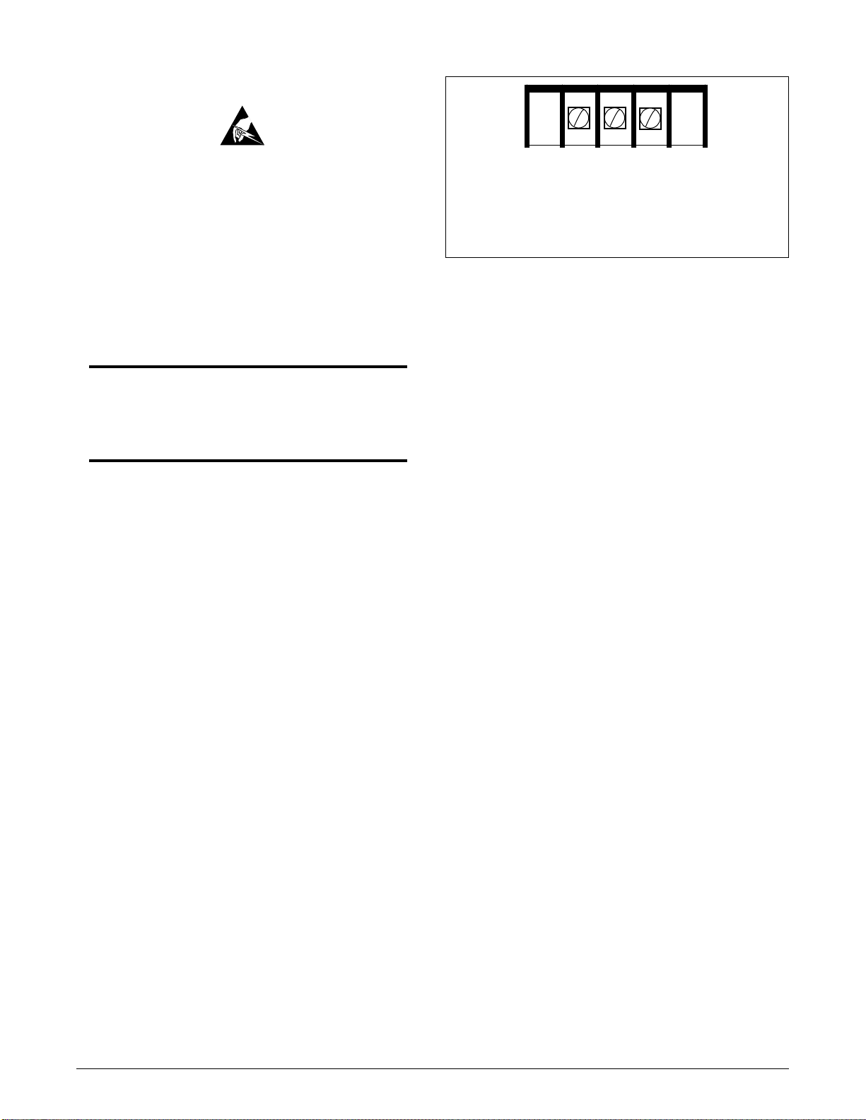
P5 is located in the connector area upper right corner
(see Figure 3). These connections are provided to
allow locally powered T400 plug-ins to be used in the
same shelf as the span powered HTU-Rs. If the shelf
is dedicated for span-powered HDSL use, the power
connections are not required.
Network connections are made using the 50-pin
amphenol connector labeled P6, NETWORK
INTERFACE.
Customer interfaces are through four RJ-48C or RJ-
48X jacks corresponding to slots one through four.
The unit ships with RJ-48C jacks installed and four
loose RJ-48X connectors. The difference in these
connectors is that the RJ-48X jacks bridge the
transmit signal upon disconnection to customer
premises equipment, thus looping back the signal
toward the network. Figure 4 shows the pins used on
the RJ-48C connectors, as well as the color-coding of
the four leads.
If replacing the RJ-48C jacks with the RJ-48X jacks,
unscrew the metal retaining clip and the four screws
securing the leads to the terminal barrier strip.
Remove the RJ-48C jack and replace it with an RJ-
48X jack. Screw down the metal retaining clip and
four leads, observing the pin number or color
convention, as shown in Figure 4.
C A U T I O N !
SUBJECT TO ELECTROSTATIC DAMAGE
OR DECREASE IN RELIABILITY.
HANDLING PRECAUTIONS REQUIRED.