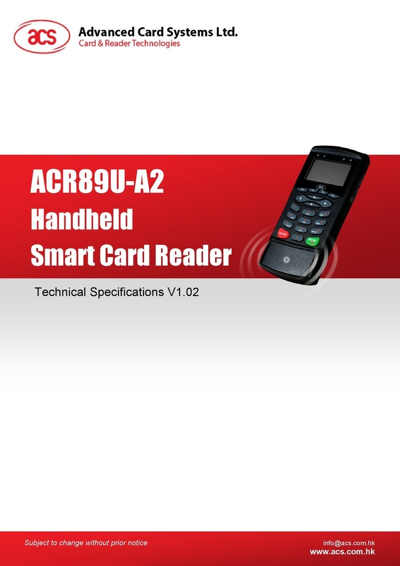
Advanced Card ACR89U-A2 User manual

Subject to change without prior notice info@acs.com.hk
www.acs.com.hk
Reference Manual V1.01
ACR89U-A2
Handheld
SmartCardReader

ACR89U-A2 – Reference Manual info@acs.com.hk
Version 1.01 www.acs.com.hk
Page 2 of 57
Table of Contents
1.0. Introduction .............................................................................................................4
2.0. Hardware Design.....................................................................................................5
2.1. Architecture............................................................................................................................5
2.2. USB Interface ........................................................................................................................5
2.3. Communication Parameters..................................................................................................5
2.4. Endpoints...............................................................................................................................6
2.5. Contact Smart Card Interface................................................................................................6
2.5.1. Smart Card Power Supply VCC (C1)............................................................................6
2.5.2. Card Type Selection......................................................................................................6
2.5.3. Interface for Microcontroller-based Cards.....................................................................6
2.6. Contactless Smart Card Interface .........................................................................................6
2.6.1. Carrier Frequency.........................................................................................................6
2.6.2. Card Polling...................................................................................................................6
3.0. ACR89 USB Communication Protocol...................................................................7
3.1. Device Configuration .............................................................................................................7
3.2. CCID Class-Specific Requests..............................................................................................9
3.2.1. Command Summary.....................................................................................................9
3.3. CCID Command Pipe Bulk-Out Message ...........................................................................10
3.3.1. Command Summary...................................................................................................10
3.4. CCID Command Pipe Bulk-IN Message..............................................................................16
3.4.1. Message Summary.....................................................................................................16
3.5. Extended Command Pipe Message Compatible with ACR89.............................................18
3.5.1. Extended Command Pipe Bulk-OUT Message ..........................................................18
3.5.2. Commands Detail........................................................................................................19
3.5.3. Extended Command Pipe Bulk-IN Message ..............................................................26
3.5.4. Messages Detail..........................................................................................................27
3.5.5. Extended Command Response Codes and Return States ........................................30
3.6. CCID Interrupt-IN Message.................................................................................................31
3.6.1. Message Summary.....................................................................................................31
3.7. CCID Error and Status Code...............................................................................................32
4.0. Software Design ....................................................................................................33
4.1. Contactless Smart Card Protocol ........................................................................................33
4.1.1. ATR Generation..........................................................................................................33
4.1.2. Pseudo APDUs for Contactless Interface...................................................................36
Appendix A. Basic Program Flow for Contactless Applications.................................52
Appendix B. Access MIFARE DESFire Tags (ISO 14443-4) .........................................53
Appendix C. Access FeliCa Tags (ISO 18092)..............................................................55
Appendix D. Access NFC Forum Type 1 Tags (ISO 18092) .........................................56
List of Figures
Figure 1 : ACR89U-A2 Architecture.......................................................................................................5
Figure 2 : CCID PC_to_RDR_Escape Message..................................................................................18
Figure 3 : PC_to_ACR89_DisplayGraphic – Bitmap Format...............................................................21
Figure 4 : CCID RDR_to_PC_Escape Message..................................................................................26
Figure 5 : Topaz Memory Map.............................................................................................................57

ACR89U-A2 – Reference Manual info@acs.com.hk
Version 1.01 www.acs.com.hk
Page 3 of 57
List of Tables
Table 1 : USB Interface Wiring...............................................................................................................5
Table 2 : ACR89 Supported CCID Features Class Descriptor...............................................................8
Table 3 : PC_to_RDR_Escape Extended Response ...........................................................................14
Table 4 : ACR89 Extended Command Pipe Messages .......................................................................18
Table 5 : Extended Command Response Codes.................................................................................30
Table 6 : Extended Command Return States.......................................................................................30
Table 7 : Extended Command Error Codes .........................................................................................30
Table 8 : CCID Error and Status Code.................................................................................................32
Table 9 : ISO 14443 Part 3 ATR Format..............................................................................................33
Table 10 : ISO 14443 Part 4 ATR Format............................................................................................35
Table 11 : Direct Transmit Response Codes........................................................................................39
Table 12 : MIFARE 1K Memory Map....................................................................................................43
Table 13 : MIFARE 4K Memory Map....................................................................................................43
Table 14 : MIFARE Ultralight Memory Map..........................................................................................44

ACR89U-A2 – Reference Manual info@acs.com.hk
Version 1.01 www.acs.com.hk
Page 4 of 57
1.0. Introduction
The ACR89U-A2 Handheld Smart Card Reader with NFC tag support is a versatile dual interface
smart card reader with PINpad, which can be used to access ISO 7816 MCU cards, ISO 14443 Type
A and B, MIFARE®, FeliCa and ISO 18092 or NFC tags. It can operate in both office and field-based
environments using it PC-linked and standalone modes, respectively.
For PC-linked Mode, ACR89U-A2 acts as the intermediary device between the PC and the card. The
reader, specifically to communicate with a contactless tag, MCU card, SAM card or device
peripherals, will carry out a command issued from the PC.
This manual describes the use of ACR89 software programming interface to control the built-in
accessories of the ACR89 multi-functional card reader. Built-in accessories are defined to be the
keypad, LCD display, LEDs, buzzer and real-time clock, embedded in ACR89. Such components are
not controlled through the smart card reader library. In addition, this document provides a guide on
implementing PC/SC APDU commands for device contactless tags.

ACR89U-A2 – Reference Manual info@acs.com.hk
Version 1.01 www.acs.com.hk
Page 5 of 57
2.0.Hardware Design
2.1. Architecture
The architecture of the ACR89U-A2 library can be visualized as the following diagram:
Figure 1: ACR89U-A2 Architecture
2.2. USB Interface
The ACR89U-A2 is connected to a computer through USB following the USB standard.
2.3. Communication Parameters
The ACR89U-A2 is connected to a computer through USB as specified in the USB Specification 2.0.,
working in full speed mode, i.e. 12 Mbps.
Pin Signal Function
1 VBUS +5 V power supply for the reader
2 D- Differential signal transmits data between ACR89U-A2 and PC
3 D+ Differential signal transmits data between ACR89U-A2 and PC
4 GND Reference voltage level for power supply
Table 1: USB Interface Wiring
Note
:
In order for the ACR89U-A2 to function properly through USB interface, the device driver should
be installed.
Application
acr89.dll
acr89fnc.sys
acr89bus.sys
CCID Layer
USB
Reader PC
PC/SC
DLL Program
Driver Program
Driver Program
Application
Program
OS
OS

ACR89U-A2 – Reference Manual info@acs.com.hk
Version 1.01 www.acs.com.hk
Page 6 of 57
2.4. Endpoints
The ACR89U-A2 uses the following endpoints to communicate with the host computer:
Control Endpoint – For setup and control purposes
Bulk OUT – For commands to be sent from host to ACR89U-A2 (data packet size is 64
bytes)
Bulk IN – For commands to be sent from ACR89U-A2 to host (data packet size is 64
bytes)
Interrupt IN – For card status message to be sent from ACR89U-A2 to host (data packet size
is 8 bytes)
2.5. Contact Smart Card Interface
The interface between the ACR89U-A2 and the inserted smart card follows the specifications of ISO
7816-3 with certain restrictions or enhancements to increase the practical functionality of the
ACR89U-A2.
2.5.1. Smart Card Power Supply VCC (C1)
The current consumption of the inserted card must not be higher than 50 mA.
2.5.2. Card Type Selection
Before activating the inserted card, the controlling PC always needs to select the card type through
the proper command sent to the ACR89U-A2.
For MCU-based cards the reader allows to select the preferred protocol, T=0 or T=1. However, this
selection is only accepted and carried out by the reader through the PPS when the card inserted in
the reader supports both protocol types. Whenever an MCU-based card supports only one protocol
type, T=0 or T=1, the reader automatically uses that protocol type, regardless of the protocol type
selected by the application.
2.5.3. Interface for Microcontroller-based Cards
For microcontroller-based smart cards only the contacts C1 (VCC), C2 (RST), C3 (CLK), C5 (GND)
and C7 (I/O) are used. A frequency of 4 MHz is applied to the CLK signal (C3).
2.6. Contactless Smart Card Interface
The interface between the ACR89U-A2 and the contactless card follows the specifications of ISO
14443 with certain restrictions or enhancements to increase the practical functionality of the ACR89U-
A2.
2.6.1. Carrier Frequency
The carrier frequency for ACR89U-A2 is 13.56 MHz.
2.6.2. Card Polling
The ACR89U-A2 automatically polls the contactless tags that are within the field. ISO 14443-4 Type A,
ISO 14443-4 Type B, MIFARE, FeliCa and NFC tags are supported.

ACR89U-A2 – Reference Manual info@acs.com.hk
Version 1.01 www.acs.com.hk
Page 7 of 57
3.0.ACR89 USB Communication Protocol
ACR89 interfaces with host (in PC-linked mode) with USB connection. CCID specifications have been
released within the industry defining such protocol for the USB chip-card interface devices. CCID
covers all the protocols required for operating smart cards and PIN. However, it does not define the
protocol for operating other peripheral features that ACR89 also has. Communication protocol for
ACR89 reader shall follow the CCID specifications and extend it to support the rest of the reader’s
features.
3.1. Device Configuration
The configurations and usage of USB end-points on ACR89 shall follow CCID Section 3. An overview
is summarized below:
1. Control Commands are sent on control pipe (default pipe). These include class-specific
requests and USB standard requests. Commands that are sent on the default pipe report
information back to the host on the default pipe.
2. CCID Events are sent on the interrupt pipe.
3. CCID Commands are sent on BULK-OUT endpoint. Each command sent to ACR89 has an
associated ending response. Some commands can also have intermediate responses.
4. CCID Responses are sent on BULK-IN endpoint. All commands sent to ACR89 have to be
sent synchronously. (i.e. bMaxCCIDBusySlots is equal to 1 for ACR89).
The supported CCID features by ACR89 are indicated in its Class Descriptor:
Offset Field Size Value Description
0 bLength 1 36h Size of this descriptor, in bytes
1 bDescriptorType 1 21h CCID Functional Descriptor type
2 bcdCCID 2 0100h CCID Specification Release
Number in Binary-Coded decimal
4 bMaxSlotIndex 1 04h Five slots are available on ACR89.
5 bVoltageSupport 1 07h ACR89 can supply 1.8V, 3.0V and
5.0V to its slots
6 dwProtocols 4 00000003h ACR89 supports T=0 and T=1
Protocol
10 dwDefaultClock 4 000012C0h Default ICC clock frequency is 4.8
MHz
14 dwMaximumClock 4 000012C0h Maximum supported ICC clock
frequency is 4.8 MHz
18 bNumClockSupported 1 00h Does not support manual setting of
clock frequency
19 dwDataRate 4 003267h Default ICC I/O data rate is 12,903
bps
23 dwMaxDataRate 4 00032673h Maximum supported ICC I/O data
rate is 206,451 bps
27 bNumDataRatesSupported 1 00h Does not support manual setting of
data rates
28 dwMaxIFSD 4 00000FEh Maximum IFSD supported by
ACR89 for protocol T=1 is 254

ACR89U-A2 – Reference Manual info@acs.com.hk
Version 1.01 www.acs.com.hk
Page 8 of 57
Offset Field Size Value Description
32 dwSynchProtocols 4 00000000h ACR89 does not support
synchronous card
36 dwMechanical 4 00000000h ACR89 does not support special
mechanical characteristics
40 dwFeatures 4 000204B2h
ACR89 supports the following
features:
- Automatic parameter configuration
based on ATR data
- Automatic ICC clock frequency
change according to parameters
- Automatic baud rate change
according to frequency and FI, DI
parameters
- Automatic PPS made by the
ACR89 according to the current
parameters
- Automatic IFSD
- Short APDU level exchange with
ACR89
44 dwMaxCCIDMessageLength 4 00000110h Maximum message length accepted
by ACR89 is 272 bytes
48 bClassGetResponse 1 FFh Echo class of APDU in Get
Response command
49 bClassEnvelope 1 FFh Insignificant (Short APDU exchange
level)
50 wLCDLayout 2 0815h 8 lines x 21 characters LCD
52 bPINSupport 1 03h ACR89 supports PIN Verification
and PIN Modification
53 bMaxCCIDBusySlots 1 01h Only 1 slot can be simultaneously
busy
Table 2: ACR89 Supported CCID Features Class Descriptor
Note: Standard CCID adopts little endian mode.

ACR89U-A2 – Reference Manual info@acs.com.hk
Version 1.01 www.acs.com.hk
Page 9 of 57
3.2. CCID Class-Specific Requests
ACR89’s USB communication with PC is based on command message format standard of ACR89
reader. This device shall support one CCID Class-specific Request. Class-specific requests are sent
via Control Pipe.
3.2.1. Command Summary
Stop any current processing command and return to a state where ACR89 is ready to accept a new
command:
bmRequestType bRequest wValue wIndex wLength Data
00100001b ABORT
(01h) bSeq, bSlot Interface 0000h None

ACR89U-A2 – Reference Manual info@acs.com.hk
Version 1.01 www.acs.com.hk
Page 10 of 57
3.3. CCID Command Pipe Bulk-Out Message
ACR89 reader follows the CCID Bulk-OUT Messages as standard CCID Session 4. In addition, this
specification defines some extended commands for operating additional features. This section lists
the CCID Bulk-OUT Messages to be supported by ACR89. The extended commands will be
introduced in Section 3.5.
3.3.1. Command Summary
3.3.1.1. PC_to_RDR_IccPowerOn
Activates the card slot and returns ATR from the card.
Offset Field Size Value Description
0 bMessageType 1 62h -
1 dwLength 4 00000000h Size of extra bytes of this message
2 bSlot 1 - Identifies the slot number for this
command.
5 bSeq 1 - Sequence number for command.
6 bPowerSelect 1 -
Voltage that is applied to the ICC:
00h = Automatic Voltage Selection
01h = 5 volts
02h = 3 volts
03h = 1.8 volts
7 abRFU 2 - Reserved for future use.
The response to this message is the RDR_to_PC_DataBlock message and the data returned is the
Answer To Reset (ATR) data.
3.3.1.2. PC_to_RDR_IccPowerOff
Deactivates the card slot.
Offset Field Size Value Description
0 bMessageType 1 63h -
1 dwLength 4 00000000h Size of extra bytes of this message
5 bSlot 1 - Identifies the slot number for this command
6 bSeq 1 - Sequence number for command
7 abRFU 3 - Reserved for future use
The response to this message is the RDR_to_PC_SlotStatus message.
3.3.1.3. PC_to_RDR_GetSlotStatus
Gets the current status of the slot.
Offset Field Size Value Description
0 bMessageType 1 65h -
1 dwLength 4 00000000h Size of extra bytes of this message

ACR89U-A2 – Reference Manual info@acs.com.hk
Version 1.01 www.acs.com.hk
Page 11 of 57
Offset Field Size Value Description
5 bSlot 1 - Identifies the slot number for this command
6 bSeq 1 - Sequence number for command
7 abRFU 3 - Reserved for future use
The response to this message is the RDR_to_PC_SlotStatus message.
3.3.1.4. PC_to_RDR_XfrBlock
Transfer data block to the ICC.
Offset Field Size Value Description
0 bMessageType 1 6Fh -
1 dwLength 4 - Size of abData field of this message
5 bSlot 1 - Identifies the slot number for this command
6 bSeq 1 - Sequence number for command
7 bBWI 1 -
Used to extend the CCIDs Block Waiting
Timeout for this current transfer. The CCID
will timeout the block after “this number
multiplied by the Block Waiting Time” has
expired.
8 wLevelParameter 2 0000h RFU (TPDU exchange level)
10 abData Byte
array - Data block sent to the CCID. Data is sent
“as is” to the ICC (TPDU exchange level).
The response to this message is the RDR_to_PC_DataBlock message.
3.3.1.5. PC_to_RDR_GetParameters
Gets the slot parameters.
Offset Field Size Value Description
0 bMessageType 1 6Ch -
1 dwLength 4 00000000h Size of extra bytes of this message
5 bSlot 1 - Identifies the slot number for this command
6 bSeq 1 - Sequence number for command
7 abRFU 3 - Reserved for future use
The response to this message is the RDR_to_PC_Parameters message.
3.3.1.6. PC_to_RDR_ResetParameters
Resets the slot parameters to default value.
Offset Field Size Value Description
0 bMessageType 1 6Dh -
1 dwLength 4 00000000h Size of extra bytes of this message

ACR89U-A2 – Reference Manual info@acs.com.hk
Version 1.01 www.acs.com.hk
Page 12 of 57
Offset Field Size Value Description
5 bSlot 1 - Identifies the slot number for this command
6 bSeq 1 - Sequence number for command
7 abRFU 3 - Reserved for future use
The response to this message is the RDR_to_PC_Parameters message.
3.3.1.7. PC_to_RDR_SetParameters
Sets slot parameters.
Offset Field Size Value Description
0 bMessageType 1 61h -
1 dwLength 4 - Size of extra bytes of this message
5 bSlot 1 - Identifies the slot number for this
command
6 bSeq 1 - Sequence number for command.
7 bProtocolNum 1 -
Specifies what protocol data
structure follows:
00h = Structure for protocol T=0
01h = Structure for protocol T=1
The following values are reserved
for future use:
80h = Structure for 2-wire protocol
81h = Structure for 3-wire protocol
82h = Structure for I2C protocol
8 abRFU 2 - Reserved for future use
10 abProtocolDataStructure Byte
array - Protocol Data Structure
Protocol Data Structure for Protocol T=0 (dwLength=00000005h)
Offset Field Size Value Description
10 bmFindexDindex 1 -
B7-4 – FI – Index into the table 7 in
ISO/IEC 7816-3:1997 selecting a clock
rate conversion factor
B3-0 – DI - Index into the table 8 in
ISO/IEC 7816-3:1997 selecting a baud
rate conversion factor
11 bmTCCKST0 1 -
B0 – 0b, B7-2 – 000000b
B1 – Convention used (b1=0 for direct,
b1=1 for inverse)
Note: The CCID ignores this bit.
12 bGuardTimeT0 1 - Extra Guardtime between two characters.
Add 0 to 254 etu to the normal guardtime
of 12etu. FFh is the same as 00h.
13 bWaitingIntegerT0 1 - WI for T=0 used to define WWT

ACR89U-A2 – Reference Manual info@acs.com.hk
Version 1.01 www.acs.com.hk
Page 13 of 57
Offset Field Size Value Description
14 bClockStop 1 -
ICC Clock Stop Support:
00h = Stopping the Clock is not allowed
01h = Stop with Clock signal Low
02h = Stop with Clock signal High
03h = Stop with Clock either High or Low
Protocol Data Structure for Protocol T=1 (dwLength=00000007h)
Offset Field Size Value Description
10 bmFindexDindex 1 -
B7-4 – FI – Index into the table 7 in
ISO/IEC 7816-3:1997 selecting a clock
rate conversion factor
B3-0 – DI - Index into the table 8 in
ISO/IEC 7816-3:1997 selecting a baud
rate conversion factor
11 BmTCCKST1 1 -
B7-2 – 000100b
B0 – Checksum type (b0=0 for LRC,
b0=1 for CRC
B1 – Convention used (b1=0 for direct,
b1=1 for inverse)
Note: The CCID ignores this bit.
12 BGuardTimeT1 1 - Extra Guardtime (0 to 254 etu between
two characters). If value is FFh, then
guardtime is reduced by 1 etu.
13 BWaitingIntegerT1 1 - B7-4 = BWI values 0-9 valid
B3-0 = CWI values 0-Fh valid
14 bClockStop 1 -
ICC Clock Stop Support:
00h = Stopping the Clock is not allowed
01h = Stop with Clock signal Low
02h = Stop with Clock signal High
03h = Stop with Clock either High or Low
15 bIFSC 1 - Size of negotiated IFSC
16 bNadValue 1 00h Only supports NAD = 00h
The response to this message is the RDR_to_PC_Parameters message.
3.3.1.8. PC_to_RDR_Escape
This command allows ACR89 to use the extended features as defined in Section 3.5.
Offset Field Size Value Description
0 bMessageType 1 6Bh -
1 DwLength 4 - Size of abData field of this message
5 Bslot 1 - Identifies the slot number for this command
6 Bseq 1 - Sequence number for command
7 AbRFU 3 - Reserved for future use

ACR89U-A2 – Reference Manual info@acs.com.hk
Version 1.01 www.acs.com.hk
Page 14 of 57
Offset Field Size Value Description
10 AbData Byte
array - Commands specified in Section 3.5.2.
The response to this message is the RDR_to_PC_Escape message.
This message could return any of the following ACR89 specific errors. Further qualification of error is
provided in the extended response.
bmICCStatus bmCommand
Status bError Description
3 1 ACR89_ERROR ACR89 specific error. Refer to
wReturnCode in ACR89 response.
3 1 INVALID_MODE ACR89 is operating in a mode that
does not support this command
3 1 DEVICE_VOID ACR89 is not initialized
Table 3: PC_to_RDR_Escape Extended Response
3.3.1.9. PC_to_RDR_Secure (RFU)
The command is reserved for future implementation.
This is a command message to allow entering the PIN for verification or modification on the card
directly.
Offset Field Size Value Description
0 bMessageType 1 69h -
1 DwLength 4 - Size of extra bytes of this message
5 BSlot 1 - Identifies the slot number for this
command
6 BSeq 1 - Sequence number for command
7 BBWI 1 -
Used to extend the CCIDs Block
Waiting Timeout for this current transfer.
The CCID will timeout the block after
“this number multiplied by the Block
Waiting Time” has expired. This
parameter is only used for character
level exchanges.
8 wLevelParameter 2 0000h RFU (TPDU exchange level)

ACR89U-A2 – Reference Manual info@acs.com.hk
Version 1.01 www.acs.com.hk
Page 15 of 57
Offset Field Size Value Description
10 bPINOperation 1 -
Used to indicate the PIN operation:
00h: PIN Verification
01h: PIN Modification
02h: Transfer PIN from secure CCID
buffer
03h: Wait ICC response
04h: Cancel PIN function
05h: Re-send last I-Block, valid only if
protocol in use is T=1
06h: Send next part of APDU, valid only
if protocol in use is T=1
11 abPINDataStructure Byte
array - PIN Verification Data Structure or PIN
Modification Data Structure
The response to this message is the RDR_to_PC_DataBlock.
Note: Refer to standard CCID Session 4.1.11 for detail PIN Verification Data Structure and PIN
Modification Data Structure.
3.3.1.10. PC_to_RDR_Abort
This command is used with the Control Pipe Abort request to tell the CCID to stop any current transfer
at the specified slot and return to a state where the slot is ready to accept a new command pipe Bulk-
OUT message.
Offset Field Size Value Description
0 bMessageType 1 72h -
1 DwLength 4 00000000h Size of extra bytes of this message
5 BSlot 1 - Identifies the slot number for this command
6 BSeq 1 - Sequence number for command
7 AbRFU 3 000000h RTF
The response to this message is the RDR_to_PC_SlotStatus message.

ACR89U-A2 – Reference Manual info@acs.com.hk
Version 1.01 www.acs.com.hk
Page 16 of 57
3.4. CCID Command Pipe Bulk-IN Message
The Bulk-IN messages are used in response to the Bulk-OUT messages. ACR89 shall follow the
CCID Bulk-IN Messages as specified in standard CCID session 4. This section lists the CCID Bulk-IN
Messages to be supported by ACR89.
3.4.1. Message Summary
3.4.1.1. RDR_to_PC_DataBlock
This message is sent by ACR89 in response to PC_to_RDR_IccPowerOn, PC_to_RDR_XfrBlock and
PC_to_RDR_Secure messages.
Offset Field Size Value Description
0 bMessageType 1 80h Indicates that a data block is being sent
from the CCID
1 dwLength 4 - Size of extra bytes of this message
5 BSlot 1 - Same value as in Bulk-OUT message
6 BSeq 1 - Same value as in Bulk-OUT message
7 bStatus 1 - Slot status and error register as defined in
Section 3.7
8 bError 1 - Slot status and error register as defined in
Section 3.7
9 bChainParameter 1 00h RFU (TPDU exchange level)
10 AbData Byte
array - This field contains the data returned
by the CCID
3.4.1.2. RDR_to_PC_SlotStatus
This message is sent by ACR89 in response to PC_to_RDR_IccPowerOff,
PC_to_RDR_GetSlotStatus, PC_to_RDR_Abort messages and class-specific ABORT request.
Offset Field Size Value Description
0 bMessageType 1 81h -
1 dwLength 4 00000000h Size of extra bytes of this message
5 BSlot 1 - Same value as in Bulk-OUT message
6 BSeq 1 - Same value as in Bulk-OUT message
7 bStatus 1 - Slot status and error register as defined in
Section 3.7
8 bError 1 - Slot status and error register as defined in
Section 3.7
9 bClockStatus 1 -
Value:
00h = Clock running
01h = Clock stopped in state L
02h = Clock stopped in state H
03h = Clock stopped in an unknown state
All other values are RFU

ACR89U-A2 – Reference Manual info@acs.com.hk
Version 1.01 www.acs.com.hk
Page 17 of 57
3.4.1.3. RDR_to_PC_Parameters
This message is sent by ACR89 in response to PC_to_RDR_GetParameters,
PC_to_RDR_ResetParameters and PC_to_RDR_SetParameters messages.
Offset Field Size Value Description
0 bMessageType 1 82h -
1 dwLength 4 - Size of extra bytes of this message
5 bSlot 1 - Same value as in Bulk-OUT
message
6 bSeq 1 - Same value as in Bulk-OUT
message
7 bStatus 1 - Slot status and error register as
defined in Section 3.7
8 bError 1 - Slot status and error register as
defined in Section 3.7
9 bProtocolNum 1 -
Specifies what protocol data
structure follows.
00h = Structure for protocol T=0
01h = Structure for protocol T=1
The following values are reserved
for future use:
80h = Structure for 2-wire protocol
81h = Structure for 3-wire protocol
82h = Structure for I2C protocol
10 abProtocolDataStructure Byte
array - Protocol Data Structure as
summarized in standard CCID
Session 5.2.3
3.4.1.4. RDR_to_PC_Escape
This message is sent by ACR89 in response to PC_to_RDR_Escape message.
Offset Field Size Value Description
0 bMessageType 1 83h -
1 dwLength 4 - Size of extra bytes of this message
5 bSlot 1 - Same value as in Bulk-OUT message
6 bSeq 1 - Same value as in Bulk-OUT message
7 bStatus 1 - Slot status and error register as defined in
Section 3.7
8 bError 1 - Slot status and error register as defined in
Section 3.7
9 bRFU 1 00h RFU
10 abData Byte
array - Depending on its corresponding extended
command, the data responded by ACR89
vary and are specified in Section 3.5.4.

ACR89U-A2 – Reference Manual info@acs.com.hk
Version 1.01 www.acs.com.hk
Page 18 of 57
3.5. Extended Command Pipe Message Compatible with ACR89
This section defines the extended commands to be accepted by ACR89 for operating additional
features that CCID does not cover. These commands are always executed under the command
PC_to_RDR_Escape Bulk-OUT message and responded with RDR_to_PC_Escape Bulk-IN
message.
PC Request Message Code ACR89 Response Message Code
PC_to_ACR89_InputKey 12h ACR89_to_PC_DataBlock 81h
PC_to_ACR89_SetCursor 18h ACR89_to_PC_DisplayStatus 83h
PC_to_ACR89_SetBacklight 19h ACR89_to_PC_DisplayStatus 83h
PC_to_ACR89_DisplayMessage 1bh ACR89_to_PC_DisplayStatus 83h
PC_to_ACR89_DisplayRowGraphic 23h ACR89_to_PC_DisplayStatus 83h
PC_to_ACR89_SetContrast 1ch ACR89_to_PC_DisplayStatus 83h
PC_to_ACR89_ClearDisplay 1dh ACR89_to_PC_DisplayStatus 83h
PC_to_ACR89_ReadRTC 08h ACR89_to_PC_TimeStamp 84h
PC_to_ACR89_SetRTC 09h ACR89_to_PC_TimeStamp 84h
PC_to_ACR89_Buzzer 0ah ACR89_to_PC_Echo 90h
PC_to_ACR89_AccessEeprom 21h ACR89_to_PC_Datablock 81h
PC_to_ACR89_SetLED 22h ACR89_to_PC_Echo 90h
PC_to_ACR89_EraseSPIFlash 30h ACR89_to_PC_ExMemStatus b0h
PC_to_ACR89_ProgramSPIFlash 33h ACR89_to_PC_MemoryStatus b0h
PC_to_ACR89GetSPIFlash 34h ACR89_to_PC_MemoryPage b1h
PC_to_ACR89_GetVersion 36h ACR89_to_PC_VersionInfo b2h
PC_to_ACR89_AuthoInfo 38h ACR89_to_PC_AuthInfo b4h
Table 4: ACR89 Extended Command Pipe Messages
3.5.1. Extended Command Pipe Bulk-OUT Message
The command format defined in this section will be the abData field to be filled in the
PC_to_RDR_Escape message.
Similar to the CCID message structure, the command format consists of fixed length Command
Header and variable length Command Data portion. The command header is fixed to 5 bytes in
length.
In contrast to CCID/USB practice, big endian will be adopted in extended command portion.
Figure 2: CCID PC_to_RDR_Escape Message
CCID Header
(10 bytes)
Extended Command
Header (5 bytes)
Extended Command
Data
CCID PC_to_RDR_Escape Message
Extended Command

ACR89U-A2 – Reference Manual info@acs.com.hk
Version 1.01 www.acs.com.hk
Page 19 of 57
3.5.2. Commands Detail
3.5.2.1. PC_to_ACR89_InputKey
This command accepts key(s) input from the user using keypad. This command context is slot
independent.
Offset Field Name Type Size Value Description
10 BCmdCode Hex 1 12h -
11 wCmdLength Hex 2 0002h Size of command data (in big
endian)
13 AbRfu Hex 2 0000h -
15 bKeyInputMode Bin 1 -
B0 – Input mode (b0=0 for single
key input, b0=1 for key string
input). In key string input mode,
the key string input is considered
completed when “Enter” key is
pressed.
B1 – Keyboard mode (b1=0 for
numeric input, b1=1 for
alphanumeric input)
B3 to b2 – Key display (b2=0 for
key display disabled, b2=1 for key
display enabled. When b2=1,
b3=0 for key display as plaintext,
b3=1 for key display as ‘*’)
B4 – Key input timeout control
(b4=0 for timeout enabled, b4=1
for timeout disabled)
B5 – Secure key transfer (b5=0
for plaintext transfer, b5=1 for
encrypted key transfer) This bit is
reserved for future
implementation.
B6 – 0/1 – disable/enable control
key
b7 – RFU
16 bTimeoutValue Hex 1 -
Key input timeout time value
counted in second. Effective only
when key input timeout control bit
of bKeyInputMode field is 0.
The response to this command is the ACR89_to_PC_DataBlock message.
3.5.2.2. PC_to_ACR89_SetCursor
This command sets the LCD position cursor to a new position. This command context is slot
independent.
Offset Field Name Type Size Value Description
10 BcmdCode Hex 1 18h -
11 wCmdLength Hex 2 0002h Size of command data (in
big endian)

ACR89U-A2 – Reference Manual info@acs.com.hk
Version 1.01 www.acs.com.hk
Page 20 of 57
Offset Field Name Type Size Value Description
13 AbRfu Hex 2 0000 Reserved for future
15 bRowPosition Hex 1 00h to 07h New cursor row position
16 bColumnPosition Hex 1 00h to 7Fh New cursor column
position
The response to this command is the ACR89_to_PC_DisplayStatus message.
3.5.2.3. PC_to_ACR89_SetBacklight
This command configures the LCD display. This command context is slot independent.
Offset Field Name Type Size Value Description
10 BCmdCode Hex 1 19h -
11 wCmdLength Hex 2 0001h Size of command data (in
big endian)
13 AbRfu Hex 2 0000 Reserved for future
15 BBacklight Hex 1 00h or 01h 00h - turns off backlight
01h - turns on backlight
Others values RFU
The response to this command is the ACR89_to_PC_DisplayStatus message.
3.5.2.4. PC_to_ACR89_DisplayMessage
This command displays a string of characters from ACR89 build-in font library. The string will be
displayed horizontally from the current cursor position. ACR89 will automatically calculate the
absolute coordinates from the character position and character size. The cursor will move accordingly.
This command context is slot dependent.
Offset Field Name Type Size Value Description
10 BCmdCode Hex 1 1Bh -
11 wCmdLength Hex 2 Var… Size of command data (in big endian)
13 AbRfu Hex 2 0000h Reserved for future
15 bCharCoding Hex 1 -
Data encoding format in abData field.
Character size depends on data
format:
00h – ASCII (1 row by 6 column per
character)
All other values are RFU
16 AbData Ascii Byte
array - Character string of encoding format
stated in bCharCoding field
The response to this command is the ACR89_to_PC_DisplayStatus message.
Other manuals for ACR89U-A2
1
Table of contents
Other Advanced Card Card Reader manuals

Advanced Card
Advanced Card ACR83 PINeasy User manual

Advanced Card
Advanced Card ACR89U-A2 User manual

Advanced Card
Advanced Card ACR88 User manual

Advanced Card
Advanced Card ACR35 User manual

Advanced Card
Advanced Card ACR128U User manual

Advanced Card
Advanced Card ACR38U-I1 User manual

Advanced Card
Advanced Card ACR122S User manual

Advanced Card
Advanced Card ACR100I User manual

Advanced Card
Advanced Card ACR38 User manual

Advanced Card
Advanced Card ACR39U-U1 User manual