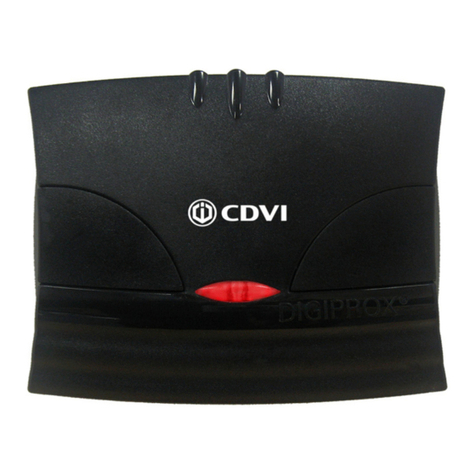
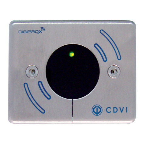
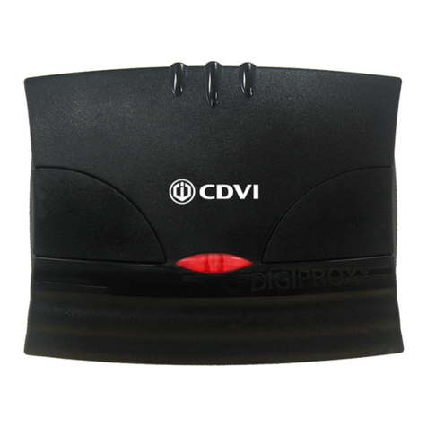
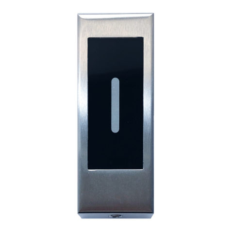
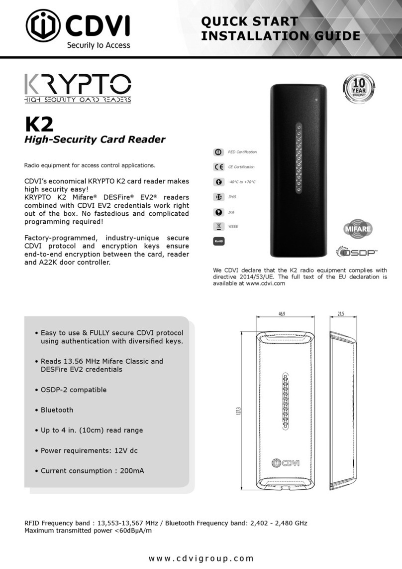
CDVI DGLPTWLC User manual

DGLPTWLC
Group Products
FRANCAIS
FR
ENGLISH
EN
MANUELD’INSTALLATION
Lecteurs Proximité intérieur/extérieur - Wiegand
Gamme: Contrôled’Accèsintégré
INSTALLATIONMANUAL
Indoor/Outdoor Proximity Card Readers - Wiegand
Range: Integratedaccesscontrol/

2cdvi.com
cdvigroup.com
IP64
-25°C to +55°C
CE Certifi cation
R&TTE Certifi cation
WEEE & RoHS
11121
DGLPTWLC
Indoor/OutdoorProximityCardreaders-Wiegand
INSTALLATION MANUAL
1] GENERAL INFORMATION
Wiegand 26, 30 and 44 bits.
Audible and visual feedback
Direct connection to the controller
through the door controller
(INTBUSW).
Flush mount.
Polycarbonate.
Sealed(resinmoulded).
Connectionby4pair6/10thcable
Inputvoltage:12VAC/DC.
Consumption:100mA.
Conforms to European directive R&TTE 99/5/CE and
according to the harmonised standards : ETS 301 489
and ETS 300-330-1-Ed 2001. Conforms to CEM applied
directives : EN 50133, EN 50130-4.
2] NOTES AND RECOMMENDATIONS
3] MOUNTING KIT
Installation recommendations
Tomaketheinstallationsecure,rememberto:
-installthevaristoronthelockingsystem,inparal-
lelonthesupplycircuit.
-placea120ohmsresistance,betweenAandB,on
thelastdoorcontrolleroftheRS485BUS.
Recommended cable
4pair6/10thcable.
Wiring reminder
Warning: do not route your wires close to cables
carryingahighcurrent(e.g.:230VAC).
Recommended power supplies
Twopowersuppliesaresuitable:
ARD12orBS60.
DGLPTWLC
reader
DGLPTWLC
Screw electronic
box jumper Varistor

3
cdvi.com
cdvigroup.com
INSTALLATION MANUAL
DGLPTWLC
Indoor/OutdoorProximityCardreaders-Wiegand
DGLPTWLC CENTAUR LINKNET
CT-V900-A LT20PB - LT20PBIP
LT20AC - LT20IP
+Inputvoltage12VDC +12V 12VDC
-
0V R2/0V 0V
H
Clock
D0
Data0 R2/D0 CL
D1
Data1 R2/D1 DA
B
Buzzer
V
GreenLED
R
RedLED
4] CONNECTIONS: DIRECTCONNECTIONTOACONTROLLER
Direct connections to the controller terminal blocks:
OFF/OFF
26bits ON
Centaur
Mode
OFF
Pullup5V
31 2 4
ON/OFF
30bits
OFF
CDVI
Mode
ON
Pullup12V
OFF/ON
44bits
ON/ON
Non
allocated
The buzzer and the LED’s can be controlled
by the reader or by an external device.
Pulls up 12 V or 5V
Opencollectoroutputs:
The controller or the
audio entry system can
manage the LED and the
buzzer to program
other operations.
In standard, when a card or a tag is
placed within the reader the orange
LED is activated and the buzzer
emit a tone. The Centaur controller
can manage the LED and the buzzer
to program other operations.
Selecttheoutputvoltage
accordingtotheinstallation.
DIPSWITCH 1 & 2 POSITIONNING DIPSWITCH 3 POSITIONNING
DIPSWITCH 4
POSITIONNING

4cdvi.com
cdvigroup.com
DGLPTWLC
Indoor/OutdoorProximityCardreaders-Wiegand
INSTALLATION MANUAL
5] CONNECTIONS: CONNECTIONTOTHEDOORCONTROLLER(INTBUSW)
Door contact (not used)
Connect E and M
Shielded
cable
Strike
DGLPTWLC
INTBUSW
Electromagnet
Varistor
To other door
controllers (INTBUSW)
Power supply
Two different confi gurations,
are possible:
12VDConly
(Asstandard)
Cutthestrap
12VACor24VDC
DGLPTWLC
8 points terminal blocks:
+
Alimentation12VDC
-
0V
H
Clock
D0
Data0
D1
Data1
B
Buzzer
V
GreenLED
R
RedLED
EN
OFF
CDVI
Mode
OFF/ON
44bits
The buzzer and the LED’s
can be controlled by the reader
or by an external device.
The controller or the audio entry system
can manage the LED and the buzzer to program
other operations.
DIPSWITCH 1 & 2
POSITIONNING DIPSWITCH 3
POSITIONNING

5
cdvi.com
cdvigroup.com
Without jumper : without clock
With jumper : with clock
INSTALLATION MANUAL
DGLPTWLC
Indoor/OutdoorProximityCardreaders-Wiegand
STAND ALONE MODE
TELACCESS
-Dipswitchaddresssetup
-Dip4=ON
DIP SWITCH adressing
1 2 3 4 Mode
ON ON ON ON Frontplate
OFF ON ON ON Reader1
ON OFF ON ON Reader2
OFF OFF ON ON Reader3
ON ON OFF ON Reader4
ST1 (Programming jumper) : Normal
CENTRALIZED MODE
-TERENA,
-UGM-UGL,
-UGP/40
-PDN345BUSPROX
-Addressprogrammingduringinstallation
-Dip4=OFF
ST1 (Programming jumper)
Normal (As standard) Installation
INTBUSW (Door controller)
Terminal block : Motherboard
VInputvoltage-
12 Inputvoltage+
1DataO
2Clock
3Data1
Terminal block : Motherboard
RN/Ccontacteletromagneticlock(+)
CCommoncontactpowersupply(+)
TN/Ocontactelectricrelease
RN/Ccontactalarm
CCommon
TN/Ocontactalarm
+ ~ - InputvoltageDCorAC,12Vor24V
P1 Request-to-enterinput
MCommon(P1etP2)
P2 Request-to-enterinput
EDoorcontact,N/C(Doorclosed)andN/O(Dooropen)
LReaderactivationimput(N/O)readerenabledand(N/C)readerdisabled
MCommon(EandM)or(EandL)
ARS485Bus(AlltheAmustbeconnectedtogetherindaisychain)
BRS485Bus(AlltheBmustbeconnectedtogetherindaisychain)
Terminal block - 3 points : Piggybackboard
7LED>Redcolor
8LED>Greencolor
9Buzzer
EN
OFF
Pullup5V
Pulls up 5V
Opencollectoroutputs:
Selecttheoutputvoltage
.
DIPSWITCH 4
POSITIONNING

6cdvi.com
cdvigroup.com
DGLPTWLC
Indoor/OutdoorProximityCardreaders-Wiegand
INSTALLATION MANUAL
6] OUTPUT FORMATS 26, 30 AND 44 BITS WIEGAND
Chronograms
Open collector output with internal pulls up 1K at +5V or +12V according the ST4 position.
26-bit Wiegand Output
ST5 jumper on 1.
Format26-bithexadecimal.Theoutputformatis26-bitWiegand(Signals:DATA1,DATA0andCLOCK)
Theframeismadeof26-bitandbuiltasfollow:
1 - First parity: 1-bit–evenparityfortherst12-bit
Codeofthebadge:6halfbyterepresentthelast6digitofthecode(4bit=1digitofacode)
Eachbyteistransferredfrombit7tobit0.
2 - Second parity: 1bit–paritéimpairedes12derniersbits
Bit 1 Bit 2 à bit 25 Bit 26
EvenParityonbit2tobit13 Data(24bit)
OddParityonbit14…bit25
Example: code of the badge is 0100166A37.
1 0001 0110 0110 1010 0011 0111 0
Parity1 1 6 6 A 3 7 Parity2
The code transmitted is in hexadecimal format 166A37
Parity 1: 0 if the number of 1 in bit 2 to bit 13 is even,
1 if the number of 1 in bit 2 to bit 13 is odd.
Parity 2: 0 if the number of 1 in bit 14 to bit 25 is odd,
1 if the number of 1 in bit 14 to bit 25 is even.
0logic
\DATA1
\CLOCK
\DATA0
50µs 50µs
2ms 2ms
1logic
EN

7
cdvi.com
cdvigroup.com
INSTALLATION MANUAL
DGLPTWLC
Indoor/OutdoorProximityCardreaders-Wiegand
Format Wiegand 30 bits
ST5 jumper on 2.
Signalsoutputinopencollectorswithpullupin30-bithexadecimalformat.Theoutputformatfromthe
proximityreaderis30-bitwiegand(Signal:DATA1,DATA0andCLOCK)andisstructuredasfollow:
1 - First parity : 1bit–evenparityfortherst14-bit
Code:Acodeisformedfrom7halfbyte.
Eachbyteistransferredfrombit7tobit0.
2 - Second parity: 1bit–oddparityforthelast14-bit
Bit 1 Bit 2 à bit 29 Bit 30
EvenParityfrombit2tobit15 Data(28-bit) OddParityfrombit16tobit29
Example A: Temic card decimal code: 689905 (in hexadecimal: A86F1).
1 0000 0000 1010 0110 0110 1111 0001 0
Parity1 0 0 A 8 6 F 1 Parity2
The code number of the card is 00A86F1 in hexadecimal
Example B: EM badge hexadecimal code: 0100166A37
1 0000 0000 0001 0001 0110 1011 0110 1
Parité1 0 0 6 6 A 3 7 Parité2
The code transmitted is in hexadecimal format 0166A37
Parity 1: 0 if the number of 1 in bit 2 to bit 15 is even,
1 if the number of 1 in bit 2 to bit 15 is odd.
Parity 2: 0 if the number of 1 in bit 16 to bit 29 is odd,
1 if the number of 1 in bit 16 to bit 29 is even.
44- bit Wiegand Format Output
ST5 jumper on 3.
44-bithexadecimalformat.Theoutputformatfromtheproximityreaderis44-bit(Signal:DATA1,DATA0
andCLOCK)andisstructuredasfollow:
1 - Data: 10digitcodenumberhexadecimalMSByterst.
Eachhexadecimaldigit=4bit,MSBitrst
2 - LRC : 4bit=orrestrictedinbetweenthedigitofthedata,MSBitrst.
Bit 1 to bit 40 Bit 41 to bit 44
DataMSBitrst LRC
Example A: EM badge hexadecimal code: 01001950C3.
0000 0000 0000 0000 0001 1001 0101 0000 1100 0011 0011
01001950C33
The code number of the card is: 01001950C3 in hexadecimal code.
EN
8cdvi.com
cdvigroup.com
1
3
2
4
DGLPTWLC
Indoor/OutdoorProximityCardreaders-Wiegand
INSTALLATION MANUAL
FixtheDGLPTWLCbox
insidethefrontpanel
(neartheheadmounting
screwhole)withdouble
sided
adhesivetape.
Connectthecable
totheboxandmake
theconnectionstothe
controllerorthepanel.
Feedthecablesthrough
themountingscrew
hole,
andtheninto
themounting
nut.
Fixthenuttothehead
studtocompletethe
installation.
Aftercheckingthatthettingkitiscomplete,youcanstartthenalinstallationofyourreader.
7] MOUNTING
8] NOTES
EN

9
cdvi.com
cdvigroup.com
INSTALLATION MANUAL
DGLPTWLC
Indoor/OutdoorProximityCardreaders-Wiegand
EN

10 cdvi.com
cdvigroup.com
FR
DGLPTWLC
LecteursProximitéencastrableWiegand-125Khz
1] PRESENTATION DES PRODUITS
2] RAPPELS ET RECOMMANDATIONS
3] KIT DE MONTAGE
MANUEL D’INSTALLATION
Wiegand 26, 30 ou 44 bits.
Signalisation lumineuse et sonore
Connexion directe sur la centrale
ou par l’intermédiaire du
contrôleur de porte (INTBUSW).
Montage encastré.
Polycarbonate.
Etanche(surmoulagerésine).
Raccordementparcâble4paires6/10e.
Alimentation:12VAC/DC.
Consommation:100mA.
Conforme à la directive européenne R&TTE 99/5/CE
et selon les normes harmonisées : ETS 301 489 et ETS
300-330-1-Ed 2001. Conforme aux normes CEM
appliquées : EN 50133, EN 50130-4.
IP64
-25°C à +55°C
Certifi cation CE
Certifi cation R&TTE
DEEE & RoHS
Recommandations d’installation
Poursécuriserl’installation,n’oubliezpasde:
-placerlavaristancesurlesystèmedeverrouillage,
enparallèle,auniveaudel’alimentation.
-placerunerésistancede120ohms,entreAetB,
surlederniercontrôleurdeporteduBUSRS485.
Câble préconisés
Câble4paires6/10ème.
Rappel de câblage
Attentiondenepaspasservoslsàproximité
decâbles«Courantfort»(ex:230VAC).
Alimentations préconisées
Deuxalimentationssontadaptées:
ARD12ouBS60.
Tête
DGLPTWLC
DGLPTWLC 11121
Ecrou Boitier Cavalier Varistance

11
cdvi.com
cdvigroup.com
DGLPTWLC CENTAUR LINKNET
CT-V900-A LT20PB - LT20PBIP
LT20AC - LT20IP
+Alimentation12VDC +12V 12VDC
-
0V R2/0V 0V
H
Clock
D0
Data0 R2/D0 CL
D1
Data1 R2/D1 DA
B
Buzzer
V
Voyantvert
R
Voyantrouge
FR
DGLPTWLC
LecteursProximitéencastrableWiegand-125Khz
MANUEL D’INSTALLATION
4] RACCORDEMENTS CONNEXIONDIRECTEÀUNECENTRALE
Raccordements directs des borniers sur les centrales :
OFF/OFF
26bits ON
Mode
Centaur
OFF
Pullup5V
31 2 4
ON/OFF
30bits
OFF
Mode
CDVI
ON
Pullup12V
OFF/ON
44bits
ON/ON
Nonattribué
Vous avez la possibilité de gérer le buzzer
et les voyants en interne ou en externe.
Pulls up 12 V ou 5V
Pourlessortiesàcollecteurouvert,il
yadeuxniveauxdesortiespossibles:
La centrale ou la platine
permettent de défi nir
les états de la LED
et du buzzer.
En standard, la lecture d’un
badge active la LED orange
et déclenche le buzzer.
La centrale Centaur permet
néanmoins de défi nir d’autres
états pour la LED et le buzzer.
Permet à l’utilisateur de choisir
la tension de sortie en fonction de
l’installation.
POSITIONNEMENT DIPSWITCH 1 & 2 POSITIONNEMENT DIPSWITCH 3
POSITIONNEMENT
DIPSWITCH 4

12 cdvi.com
cdvigroup.com
FR
DGLPTWLC
LecteursProximitéencastrableWiegand-125Khz
5] RACCORDEMENTS CONNEXIONAVECCONTRÔLEURDEPORTE(INTBUSW)
MANUEL D’INSTALLATION
Si vous ne souhaitez
pas de gestion de l’etat
porte : Relier E et M
Câble
blindage
Gâche
DGLPTWLC
INTBUSW
Ventouse
Varistance
Vers d’autres contrôleur
de portes (INTBUSW)
Alimentation
Pour l’alimentation,
il y a deux modes possibles :
12VDCuniquement
(Congurationusine)
Coupezlestrap
12VACou24VDC
DGLPTWLC
Bornier 8 points :
+
Alimentation12VDC
-
0V
H
Clock
D0
Data0
D1
Data1
B
Buzzer
V
Voyantvert
R
Voyantrouge
OFF
Mode
CDVI
OFF/ON
44bits
Vous avez la possibilité de gérer
le buzzer et les voyants en interne
ou en externe.
La centrale ou la platine permettent
de défi nir les états de la LED et du buzzer.
POSITIONNEMENT
DIPSWITCH 1 & 2 POSITIONNEMENT
DIPSWITCH 3

13
cdvi.com
cdvigroup.com
FR
DGLPTWLC
LecteursProximitéencastrableWiegand-125Khz
MANUEL D’INSTALLATION
Sans cavalier : sans clock
Avec cavalier : avec clock
MODE AUTONOME
TELACCESS
-Programmationdel’adressepardipswitch
-Dip4=ON
Adressage DIPSWITCH
1 2 3 4 Mode
ON ON ON ON Façade
OFF ON ON ON Lecteur1
ON OFF ON ON Lecteur2
OFF OFF ON ON Lecteur3
ON ON OFF ON Lecteur4
ST1 (Cavalier de programmation) : Normal
MODE CENTRALISÉ
-TERENA,
-UGM-UGL,
-UGP/40
-PDN345BUSPROX
-Programmationdel’adresseparinstallation
-Dip4=OFF
ST1 (Cavalier de programmation)
Normal (Confi g. usine) Installation
INTBUSW (Contrôleur de porte)
Bornier 5 points : Cartemère
VAlimentation-
12 Alimentation+
1DataO
2Clock
3Data1
Bornier 16 points : Cartemère
RContactN.FporteVentouse(+)
CContactcommun+Alimentation
TContactN.OporteGâche
RContactN.Falarme
CContactcommun
TContactN.Oalarme
+ ~ - AlimentationDCouAC12Vou24VDC
P1 Boutonpoussoirintérieur
MMassecommune(P1etP2)
P2 Boutonpoussoirextérieur
EContactfermetureporte,N.F.(Portefermée)etN.O.(Porteouverte)
LContactautorisationlecturedubadge(N.O)autoriséeet(N.F)interdite
MMassecommune(EetM)ou(EetL)
ABusRS485(touslesAdoiventêtrereliésentreeuxsouslaformed’unechaîne)
BBusRS485(touslesBdoiventêtrereliésentreeuxsouslaformed’unechaîne)
Bornier 3 points : Cartelle
7Signalisation>couleurrouge
8Signalisation>couleurverte
9Buzzer
OFF
Pullup5V
Pulls up 12 V ou 5V
Pourlessortiesàcollecteurouvert,il
yadeuxniveauxdesortiespossibles:
Permet à l’utilisateur de choisir
la tension de sortie.
POSITIONNEMENT
DIPSWITCH 4

FR
14 cdvi.com
cdvigroup.com
DGLPTWLC
LecteursProximitéencastrableWiegand-125Khz
MANUEL D’INSTALLATION
6] FORMAT DE SORTIE WIEGAND 26, 30 ET 44 BITS
Chronogrammes
Sorties en collecteur ouvert avec pulls up internes de 1K au +5V ou +12V selon la position de ST4
Format Wiegand 26 bits
Cavalier ST5 sur 1.
Format26bitshexadécimal.
Lacommunications’effectueparuneliaisondetypeWiegand26bits
(Signaux:DATA1,DATA0etCLOCK).
Latrameestconstituéed’unetotalitéde26bits
etsedécomposecommesuit:
1 - 1ère parité : 1bit–paritépairedes12premiersbits
Codedubadge:3motsd’unoctetreprésentantles6dernierstermes.
Chaquemotesttransmisbitdepoidsfortenpremier.
2 - 2ème parité: 1bit–paritéimpairedes12derniersbits
Bit 1 Bit 2 à bit 25 Bit 26
Paritépairesurbit2àbit23 Donnée(24bits)
Paritéimpairesurbit14àbit25
Exemple : pour un badge dont le code hexadécimal est 0100166A37.
1 0001 0110 0110 1010 0011 0111 0
Parité1 1 6 6 A 3 7 Parité2
Le code émis est 166A37 en hexadécimal
Parité 1 : 0 si le nombre de 1 dans bit 2 à bit 13 est paire,
1 si le nombre de 1 dans bit 2 à bit 13 est impaire.
Parité 2 : 0 si le nombre de 1 dans bit 14 à bit 25 est impaire,
1 si le nombre de 1 dans bit 14 à bit 25 est paire.
0logique
\DATA1
\CLOCK
\DATA0
50µs 50µs
2ms 2ms
1logique

FR
15
cdvi.com
cdvigroup.com
DGLPTWLC
LecteursProximitéencastrableWiegand-125Khz
MANUEL D’INSTALLATION
Format Wiegand 30 bits
Cavalier ST5 sur 2.
Format30bitshexadécimal.
Lacommunications’effectueparuneliaisondetypeWiegand30bits(Signaux:
DATA1,DATA0etCLOCK).
Latrameestconstituéed’unetotalitéde30bitsetsedécomposecommesuit:
1 - 1ère parité : 1bit–paritépairedes14premiersbits
Codedubadge:7quartetsreprésentantlecodedubadge
Chaquemotesttransmisbitdepoidsfortenpremier.
2 - 2ème parité: 1bit–paritéimpairedes12derniersbits
Bit 1 Bit 2 à bit 29 Bit 30
Paritépairesurbit2àbit15 Donnée(28bits) Paritéimpairesurbit16àbit29
Exemple A : pour une carte ayant le code décimal : 689905 (en hexadécimal : A86F1).
1 0000 0000 1010 0110 0110 1111 0001 0
Parité1 0 0 A 8 6 F 1 Parité2
Le code émis est 00A86F1 en hexadécimal
Exemple B : pour un badge ayant le code hexa : 0100166A37
1 0000 0000 0001 0001 0110 1011 0110 1
Parité1 0 0 6 6 A 3 7 Parité2
Le code émis est 0166A37 en hexadécimal
Parité 1 : 0 si le nombre de 1 dans bit 2 à bit 15 est paire
1 si le nombre de 1 dans bit 2 à bit 15 est impaire
Parité 2 : 0 si le nombre de 1 dans bit 16 à bit 29 est impaire
1 si le nombre de 1 dans bit 16 à bit 29 est paire
Format Wiegand 44 bits
Cavalier ST5 sur 3.
Format44bitshexadécimal.Lacommunications’effectueparuneliaisondetypeWiegand44bits(Signaux:
DATA1,DATA0etCLOCK).Latrameestconstituéed’unetotalitéde44bitsetsedécomposecommesuit:
Données : 10chiffreshexadécimaux(octetdepoidsfortenpremier),
Chaquechiffrehexadécimal=4bits(bitdepoidsfortenpremier).
LRC : 4bit=OUexclusifentreleschiffresdeladonnée(bitdepoidsfortenpremier).
Bit 1 à bit 40 Bit 41 à bit 44
Codedubadge LRC
Exemple A : pour un badge ayant le code hexa : 01001950C3.
0000 0000 0000 0000 0001 1001 0101 0000 1100 0011 0011
01001950C33
Le code émis est : 01001950C3 en hexadécimal.

1
3
2
4
16 cdvi.com
cdvigroup.com
FR
DGLPTWLC
LecteursProximitéencastrableWiegand-125Khz
Fixez le boîtier du DGLP-
TWLCàl’intérieurdelafa-
çade (à proximité du trou
dexationdelatête)avec
unadhésifdouble-face.
Branchez le câble sur le
boîtier et effectuez les
branchementsverslacen-
traleouplatine.
Passez les câbles dans le
troude xation,puisdans
l’écroudexation.
Fixezl’écrou sur le pasde
visdelatêtepournaliser
l’installation.
Aprèsavoirvériéquelekitdemontageestcomplet,vousallezpouvoirprocéderàl’installationnalede
votrelecteur.Réunissezlematérielapproprié(Perceuse,tournevis,mètre,...)etsuivezlesrecommandations
demontagequicorrespondentaulecteurquevousallezinstaller.
7] MONTAGE
8] NOTES
MANUEL D’INSTALLATION

17
cdvi.com
cdvigroup.com
FR
DGLPTWLC
LecteursProximitéencastrableWiegand-125Khz
MANUEL D’INSTALLATION

18 cdvi.com
cdvigroup.com
FR
DGLPTWLC
LecteursProximitéencastrableWiegand-125Khz
MANUEL D’INSTALLATION

19
cdvi.com
cdvigroup.com
FR
DGLPTWLC
LecteursProximitéencastrableWiegand-125Khz
MANUEL D’INSTALLATION

Manufacturing Access Control since 1985
cdvigroup.com
Reference : G0301FR0318V03
Extranet :EXE-CDVI_IMDGLPTWLCCMYKA5EN-FR03
Alltheinformationcontainedwithinthisdocument(photos,drawing,features,specicationsanddimensions)
couldbeperceptiblydifferentandcanbechangedwithoutpriornotice.
Touteslesinformationsmentionnéesàtitreindicatifsurleprésentdocument(photos,dessins,caractéristiques
techniquesetdimensions)peuventvarieretsontsusceptiblesdemodicationssansnoticationpréalable.
CDVI Group
FRANCE(Headquarters/Siègesocial)
Phone:+33(0)148910102
Fax:+33(0)148912121
CDVI
FRANCE
Phone:+33(0)148910102
Fax:+33(0)148912121
CDVIAMERICAS
[CANADA-USA]
Phone:+1(450)6827945
Fax:+1(450)6829590
CDVIBENELUX
[BELGIUM-NETHERLAND-LUXEMBOURG]
Phone:+32(0)56620250
Fax:+32(0)56620255
CDVI
TAIWAN
Phone:+886(0)424712188
Fax:+886(0)424712131
CDVI
SWITZERLAND
Phone:+41(0)218821841
Fax:+41(0)218821842
CDVI
CHINA
Phone:+86(0)1087664065
Fax:+86(0)1087664165
CDVIIBÉRICA
[SPAIN-PORTUGAL]
Phone:+34(0)935390966
Fax:+34(0)935390970
CDVI
ITALIA
Phone:+390331973808
Fax:+390331973970
CDVI
MAROC
Phone:+212(0)522480940
Fax:+212(0)522483469
CDVISWEDEN
[SWEDEN-DANEMARK-NORWAY-FINLAND]
Phone:+46(0)317601930
Fax:+46(0)317480930
CDVIUK
[UNITEDKINGDOM-IRELAND]
Phone:+44(0)1628531300
Fax:+44(0)1628531003
DIGIT
FRANCE
Phone:+33(0)141710685
Fax:+33(0)141710686
Table of contents
Languages:
Other CDVI Card Reader manuals

CDVI
CDVI KRYPTO K1BT Instruction Manual

CDVI
CDVI SOLARPW User manual

CDVI
CDVI SOLARMWD User manual

CDVI
CDVI U4Go Series User manual

CDVI
CDVI Mifare Desfire EV1 User manual

CDVI
CDVI DGLPWLC User manual

CDVI
CDVI NANOPB Instruction Manual

CDVI
CDVI DGLP60WLC User manual

CDVI
CDVI DGLPM WLC User manual

CDVI
CDVI MOONARW User manual

CDVI
CDVI NANOPW User manual

CDVI
CDVI SOLARPW User manual

CDVI
CDVI Mifare SOLARMW User manual

CDVI
CDVI SOLARKPW User manual

CDVI
CDVI KRYPTO K2I User manual

CDVI
CDVI DESFire EV2 Instruction Manual

CDVI
CDVI KRYPTO K2 Instruction Manual

CDVI
CDVI U4GO A6U48 User manual

CDVI
CDVI DGLPWLC User manual

CDVI
CDVI DGLIMWLC User manual